The composition of earthworks in construction. Earthworks Types of earthworks
Russian joint-stock company
Gazprom system of regulatory documents in the construction of the arrangement of the rules of structures
Main Gas Pipeline Code of Rules for Construction
Linear part of gas pipelines
Earthwork production
SP 104-34-96.
Approved RAO Gazprom
(Order of September 11, 1996 No. 44)
Set of rules
Code of Rules for the Construction of Main Gas Pipelines
C ODE OF THE REGULATIONS ON CONSTRUCTION OF TRUNK GAS PIPELINES
Date of introduction 10/11/1996
Earthwork production
Developed by the Association "High-Template Pipeline Transport", RAO Gazprom, Rosneftegazstroy JSC, JSC VNIist, NGS-OrgProektconomika JSC. Coordinated with the Ministry of Travel of the Russian Federation by letter No. 13/567 of December 7, 1995
Under the general editor
acad. B.E. Paton, Cand. tehn Science V.A. Dinkova. prof. OM Ivantsova
Introduction
In this Code of Rules (SP), in order to ensure year-round construction and the possibility of a flow-mechanized fulfillment of the entire complex of construction and installation work, especially in difficult conditions, compliance with the structural parameters of pipeline elements during laying and the requirements of their reliability during operation, modern progressive methods of organization are reflected and technology production, quality control and acceptance earth structures In various climatic and ground zones. The rules summary are summarized the results of research and design development, as well as best practices for the production of earthworks accumulated by construction organizations in domestic and foreign practice when building linear objects. In this joint venture, new ways of manufacturing work on the construction of main pipelines in complex climatic conditions are proposed, reflected methods for the development of trenches, the construction of embankments, drilling holes and wells for silent supports, backfilling trenches, taking into account the design parameters of pipelines, the specificity of the production of drilling works, including including with parallel laying of multi-triggered highways in different parts of the track. This joint venture is intended for specialists of construction and design organizations engaged in the production of earthworks during the construction of the linear part of pipelines, as well as the development of projects for organizing construction and work production (PRP).Terminology
Trench - removal is usually a significant length and a relatively small width, intended for laying the paved pipeline. A trench as a temporary earthwork is developed in certain parameters depending on the diameter of the pipeline under construction and can be arranged with slopes or vertical walls . The dump is usually called the soil stacked along the trench when it is developing earthmoving machines. Mound - Earth facilities intended for laying pipelines when crossing low or complex areas of terrain, as well as for the device on them, road canvas or softening the profile of the route when planning a construction band by additional soil swelling. Receptions - Earth facilities, suitable by cutting of the soil when mitigating the longitudinal profile of the route and laying roads along the pipeline construction strip. Semi-willed semi-satisfying facilities, combining signs of removing and embankment, intended for laying pipelines and roads on steep skeres (mostly transverse slopes). Ditch - structures in the form of linear recesses, suitable usually for draining the construction strip, they are often called drainage or drainage. Ditches that serve to intercept and remove the water flowing from the over-site territory and arranged with the riding side of the side of the earth facility are called Nagorno. Ditches that serve to remove water and located along both borders of the leaving or roads are called cuvettes. The ditches deployed during the construction of pipelines (ground-based) on the swamps along the boundaries of the outlet strip and serving for water storage are called fire ducts. Cavaliers are called embankments, swelling from an excessive soil formed in the development of recesses, and located along the latter. Reserves are usually called the recesses, the soil of which is used on the sinking of the nearby embankments. The reserve is separated from the attachment of the slope of the embankment by protective berm. The quarry is a specially developed secession for the use of soil when squeezing in bulk and located at a considerable distance from them. The channel is the extrusion of considerable length and filled with water. Channels are usually suitable for the construction of pipelines in the swamps and wetlands and serve as a trench for laying the pipeline by the alloy method or as the main channel of the drainage system of the drainage system. The constructive elements of the trench are the trench profile, the soil dumping, roller over the trench (after its sweeping ground). The structural elements of the embankment are an earthen canvas, cuvettes, cavaliers and reserves. Trench profile, in turn, has the following characteristic elements: bottom, walls, brow. Mounds have: base, slopes, soles and breaks of slopes, comb. Bed - a layer of loose, usually sandy soil (10 - 20 cm thick), dumbfounded on the bottom of the trench in rock and frozen soils for protection from mechanical damage to the insulating coating when laying the pipeline into the trench. Attachment is a layer of soft (sandy) soil, dumbfounded over a pipeline laid in a trench (20 cm thick), before filling it with a loose rock or frozen soil to the design mark of the earth's surface. The overlooking layer of the soil is the mineral soft top layer of the soil, which runs over the mainland rocks to be priority removal (opening) from the construction strip, for the subsequent efficient development of the rock soil by the drilling method. The sheets are cylindrical cavities in the ground with a diameter of up to 75 mm and a depth of no more than 5 m, formed by drilling plants to accommodate the charges of explosives when the durable soils drowned with a drilling circulating method (for the construction of trenches). Well-cylindrical cavities in the ground with a diameter of over 76 mm and a depth of more than 5 m, formed by the drilling machines to accommodate in them charges of explosives in the production of drill-up work, both for jams and explosions to reset when the shelves in the mining area. The complex sequential method is the method of developing trenches mainly in high-strength perplexed soils for ballastized pipelines with a diameter of 1420 mm, which consists in a sequential passage of the trench of several types of rotary trench excavators, or rotary excavators of one type with different parameters of the working body for a device of the trench of the project profile (up to 3 3m). Technological gap - the distance along the front between the invigoles of the production of certain types of work of the technological process of construction of the linear part of the main pipeline within the bandwidth (for example, the technological gap between the preparatory and earthworks, between welding and insulating-stacked, and during the production of earthworks in rock Soils gap between brigades in stripped, drilling, explosive work and the development of trenches of excavators in the burst explosion of soils). Playful quality control of the quality of work is the continuous technological process of quality control, carried out in parallel with the implementation of any construction and installation operation or process, is performed in accordance with the construction of the linear part of the main pipelines by technological cards of playback quality control. The technological map of the advance control of the quality of earthworks reflects the main provisions on the technology and organization of the open control, technological requirements for machines, determines the main processes and operations to be controlled by controlled indicators, characteristic of the implementation of earthworks, composition and types of control, as well as the Form of Executive Documentation, which registers the results of control.1. General Provisions
1.1. The technology of the entire complex of earthworks, including engineering training, for compliance with the required sizes and profiles of earthquakes, as well as regulated tolerances for the production of earthworks, must be carried out in accordance with the project developed taking into account the requirements of the current requirements regulatory documents: ¨ "Main pipelines" (SNIP III-42-80); ¨ "Organization of construction production" (SNiP 3.01.01-80); ¨ "Earth structures. Bases and foundations "(SNiP 3.02.01-87); ¨ "Land removal standards for main pipelines" (CH-452-73) of the Fundamentals of the Land Legislation of the Union of SSR and the Union republics; ¨ "Construction of trunk pipelines. Technology and organization "(VNC 004-88, Minneftegazstroy, P, 1989); ¨ RF Law on Environmental Protection; ¨ Technical rules for conducting explosive work on the day surface (M., Subraz, 1972); ¨ Instructions for the production of explosive work in frozen pounds near the active steel underground main pipelines (VNF-2-115-79); ¨ This set of rules. Detailed development of technology and organizational measures is carried out in the preparation of technological maps and projects for the production of work on specific production processes, taking into account the specifics of the embossed and soil conditions of each part of the pipeline route. 1.2. Excavation It should be done with the provision of quality requirements and with the mandatory operational control of all technological processes. All units for the production of earthworks are recommended to provide cards of playback quality control, which are developed in the development of PDP and PPR, schemes of integrated mechanization for the construction of main pipelines design and design organizations of the industry. 1.3. The production of earthworks must be carried out in compliance with the rules for safety, production sanitation and the latest achievements in the field of labor protection. The entire set of earthworks during the construction of pipelines is carried out in accordance with the projects of the construction and production of work. 1.4. The technology and organization of earthworks should include the flow of their production, the year's year's year, including in complex areas of the track, without a significant increase in their labor intensity and cost, while maintaining the specified pace of work. The exception is to work on the perplexed soils and the wetlands of the Far North, where the work is recommended only during the period of soil freezing. 1.5. Management and labor protection guide, as well as responsibility for ensuring the conditions for compliance with labor protection requirements in specialized divisions, it is recommended to impose on the managers, supervisors and the main engineers of these organizations. At the work of work, the responsibilities for compliance with these requirements are bonds of sites (columns), pro-paper and master. 1.6. Construction machines and equipment for earthworks must comply with the technical conditions of operation, taking into account the conditions and nature of the work performed; In the northern regions with low air temperatures, it is recommended to mainly apply machines and equipment in the northern execution. 1.7. During the construction of the main pipelines of the Earth, provided for temporary use, it is necessary to bring in accordance with the requirements of the project of internal land management of the respective land users: · In the production of earthworks, it is not recommended to use techniques and methods that promote the wash, blowing and wiring soils and soils, the growth of ravines, overlapping the sands , the formation of village fluxes and landslides, salinization, soil fever and other forms of fertility loss; · When drafting the open drainage bandwidth should not be discharged by drainage water to the sources of water supply, therapeutic water resources, resting and tourism sites.2. Production of earthworks. Land Recultivation Work
2.1. The production of work on the removal and restoration of the layer within the construction strip is recommended to be performed in accordance with the special project of land reclamation. 2.2. The land recultivation project should be developed by project organizations, taking into account the specifics of the specific sections of the route and be agreed with land users of these areas. 2.3. Fertile lands are given in a suitable condition, as a rule, in the process of construction work on the pipeline, and if it is impossible - no later than during the year after the completion of the entire complex of work (in coordination with the land user). All work should be completed during the drainage of land for construction. 2.4. In the project of land reclamation in accordance with the terms of the presentation of land for use and, taking into account local natural-climatic features, should be identified: ¨ Borders of land on the pipeline highway, in which recultivation is needed; ¨ thickness of the removable fertile soil layer for each site to be reclaimed;
Fig. Circuit diagram of the strip of removal during the construction of trunk pipelines
A - minimum strip width, in which the fertile layer of the soil is removed (trench width at the top plus 0.5 m in each direction)
¨ Width of the reclamation zone within the bandwidth; ¨ The location of the dump for the temporary storage of the removed fertile layer of the soil; ¨ Methods for applying a fertile layer of soil and restoration of its fertility; ¨ permissible excess of the applied fertile soil layer over the level of undisturbed lands; ¨ Methods of sealing of a loose mineral soil and a fertile layer after filling the pipeline. 2.5. Work on the removal and application of the fertile layer of the soil (technical reclamation) produce the forces of a construction organization; The restoration of soil fertility (biological recultivation, including fertilizer seeding, the restoration of moss in the northern regions, plowing of fertile soils and other agricultural works) produce land users at the expense of the funds provided for by the estimate for reclamation, included in the consolidated estimate of construction. 2.6. In developing and coordinating the project of land reclamation for the pipeline parallel to the current gas pipeline, its actual position should be taken into account, the actual depth of the occurrence and technical condition, and on the basis of these data, develop design decisions that ensure the safety of the current pipeline and the safety of the work of work in accordance with "Instructions for the production of work in the security zone of main pipelines" and the current safety regulations. 2.7. When laying a pipeline parallel to the current pipeline, it should be borne in mind that the operating organization before the start of work should be denoted by the location of the axis of the active pipeline, determine and designate dangerous places (sections of insufficient shutoff and sections of the pipeline in poor condition). During the production period near the existing pipelines or at intersection with them, the presence of representatives of the operating organization is necessary. Executive documentation for hidden work should be drawn up in the forms given in VNC 012-88, part II. 2.8. The technology of work on technical reclamation of disturbed lands in the construction of the main pipelines is to remove the fertile layer of the soil prior to the start of construction work, transporting it to the place of temporary storage and applying it to the restored land at the end of construction work. 2.9. In the warm season, the removal of the fertile layer of the soil and its movement to the dump should be produced by a rotary reclamation of ETR type 254-05, as well as bulldizers (type D-493a, D-694, D-385A, D-522, DZ-27C) transverse strokes with a layer thickness up to 20 cm and transverse - with a layer thickness more than 20 cm. With the thickness of the fertile layer to 10 - 15 cm, it is recommended for removing and moving it into the removal to apply automatic drivers. 2.10. The removal of the fertile soil layer should be made on the entire design thickness of the reclamation layer, if possible, in one pass or layer in several passes. In all cases, it is impossible to allow mixing of the fertile soil layer with mineral soil. The extra mineral soil, formed as a result of the volume of the volume when laying the pipeline into the trench, in accordance with the project can be evenly distributed and is planned on the strip of the fertile soil layer (before applying the latter) or exported beyond the construction strip in the specified place. The removal of excess mineral soil is carried out in two schemes: 1. After filling on the trench, the mineral soil is a bulldozer or an automotive drive is evenly distributed through the strip to be reclamation, then after its seal, the soil cuts are performed by strokes (type D-357M, D-511C, etc.) to the desired depth with such a calculation to ensure that the excess of the level applied Fertile soil layer over the surface of undisturbed lands. Stashes the soil is transported in the place specifically listed in the project; 2. Mineral soil after leveling and sealing is cut and moved by a bulldozer along the strip and laid in order to increase the efficiency of its loading for transport to special boots with a height of up to 1.5 - 2.0 m to 150 - 200 m 3 From where it is single-dock excavators (such as 4225, equipped with a straight bucket with a straight shovel or grapple), or by single-line front loaders (type TO-10, TO-28, TO-18) loaded into the automotive industry and exported beyond the construction strip in the place specified in the project. The first scheme is recommended for the distance removal of the soil up to 0.5 km, the second is more than 0.5 km. 2.11. If, at the request of land users, the project also provides for the export of the fertile soil layer beyond the construction strip into special temporary dumps (for example, on particularly valuable lands), then removal and transporting it to a distance of up to 0.5 km should be made by staples (type DZ-1721). When removing the soil at a distance of more than 0.5 km, it is necessary to use automotive vehicles (such as MAZ-503B, KRAZ-256B) or other machines. Loading the fertile layer (also pre-shifted in the bright) on dump trucks in this case is recommended to be performed by front loaders (type TO-10, D-543), as well as single-line excavators (such as EO-4225), equipped with a straight shovel or graising bucket. Payment of all these works should be provided in an additional estimate. 2.12. The removal of the fertile soil layer is usually produced before the onset of stable negative temperatures. In exceptional cases, in coordination with land users and control bodies, the fertile layer of soil in winter conditions is allowed. When performing work on the removal of the fertile soil layer in the winter time of the year, a frozen fertile layer of soil is recommended to develop bulldozers (type DZ-27C, DZ-34C, "Internet Harvester" TD -25C) with preliminary loosening it with three-volume rippers (DP-26C type, DP -9C, U-RK8, U-RCA, "International Harveterster" TD-25C), Rippers of the brand "Caterpiller (model 9B) and others. Swimming should be made to a depth not exceeding the thickness of the fertile soil layer. When the soil loaned, the tractor rippers are recommended to use a longitudinal-turning technological scheme. For the removal and movement of the fertile soil layer can be used in winter rotary trench excavators (such as ETR-253A, ETR-254, ETR-254AM, ETR-254AM-01, ETR-254-05, ETR-307, ETR-309). The depth of the rotor immersion should not exceed the thickness of the removable fertile layer of the soil. 2.13. Filing of the pipeline with mineral soil is produced at any time of the year immediately after it laying. For this, rotary tranches and bulldozers can be used. In the warm season after filling in the pipeline, the mineral soil produces its seal with vibration seals of the type D-679, pneumatic cathips or multiple (three or five times) passages of tracked tractors over covered mineral soil pipelines. Sealing mineral soil in this way is performed before filling in the pipeline by the transported product. 2.14. In winter, an artificial seal of mineral soil is not produced. The soil acquires the necessary density after thawing for three to four months (natural seal). The sealing process can be accelerated by moisturizing (soaking) of soil with water into a covered trench. The same seal method can be recommended when there is a product in the pipeline during the reclamation period. 2.15. The applying of the fertile soil layer should be made only in the warm season (with normal humidity and sufficient carrier capacity of the soil for the passage of machines). For this purpose, bulldozers operating transverse moves, moving and leveling the fertile layer of soil are used. This method is recommended to be used with a thickness of a fertile layer over 0.2 m. The final layout can be performed by the longitudinal passages of the automotive drivers. 2.16. If it is necessary to transport the fertile layer of the soil to the place of application of it from the dumps located outside the construction strip and removed from it to 0.5 km, screensions (type DZ-1721) can be used. With the distance of transportation exceeding 0.5 km, the fertile layer of the soil is delivered using automobiles with the subsequent resurrection by its bulldozers working with ocopyar or longitudinal strokes. Running the fertile layer of the soil can also be carried out by high-drivers (such as DZ-122, DZ-98B, equipped in the front of the knife-blade). The attraction of earthy sites in a suitable condition is carried out during the work, and if it is impossible, no later than during the year after the completion of the work. 2.17. Control over the correctness of the work in accordance with the project recultivation project is carried out by state control bodies on the use of land on the basis of the state approved by the Government. The transfer of land services to the restored land should be issued as an asset in the prescribed manner.
3. Earthworks under normal conditions
3.1. The technological parameters of the earth structures used in the construction of the main pipelines (width, depth and slope of the trench, cross-section of the mound and the steepness of its slopes, the operating parameters and wells) are mounted depending on the diameter of the paved pipeline, the method of its fixing, terrain, ground conditions and are determined project. The size of the trench (depth, width along the bottom, slope) is set depending on the purpose and external parameters of the pipeline, the type of ballasting, the characteristics of soils, hydrogeological and relief conditions of the area. Specific parameters of earth structures are defined by working drawings. The trench depth is set from the conditions of pipeline prevention from mechanical damage when moving through it vehicles, construction and agricultural machinery. The depth of the trench when laying the main pipelines is taken equal to the diameter of the pipe plus the necessary amount of soil swelling above it and is assigned to the project. At the same time, it should be (accordingly Snip 2.05.06-85) at least: · with diameter less than 1000 mm ........................... .................................................. ...... 0.8 m; · With a diameter of 1000 mm and more ........................................... ..................................... 1.0 m; · On the swamps or peat soils to be drained ................................. 1.1 m; · In sand vegans, counting from the lower marks of interbarchanny bases ... 1.0 m; · In rocky soils, swampy terrain in the absence of driving vehicles and agricultural machinery .................................... ................. 0.6 m. The minimum trench width of the pione is assigned to SNiP and is taken at least: ¨ D + 300 mm - for pipelines with a diameter of up to 700 mm; ¨ 1.5 D - for pipelines with a diameter of 700 mm and more on the following additional requirements: for pipelines with a diameter of 1200 and 1400 mm with a digging of trenches with slopes not cooler 1: 0.5 The width of the trench for the bottom is allowed to decrease to the value of D + 500 mm. where D is the conditional diameter of the pipeline. When developing a soil with earthmoving machines, the trench width is recommended to make an equal width of the cutting edge of the working body of the machine adopted by the construction organization project, but not least above. When ballasting the pipeline by webly loads or fixing the anchor devices, the width of the trench for the bottom must be taken at least 2.2 D, and for the pipeline with thermal insulation is set by the project. The width of the trench for the bottom on the curves of sections from the knees of forced bending is recommended to be taken equal to the two-time magnitude relative to the width in rectilinear areas. 3.2. At the beginning of the work on the ruin of trench, it is recommended to obtain: · Written permission for the right to produce earthworks in the zone of underground communications issued by the organization responsible for the operation of these communications; · Draft production of earthworks, when developing type technological maps; · Distribution of the excavator crew (if the work is performed jointly with bulldozers and rippers, then the machinists of these machines) on the production of work. 3.3. Before developing a trench, you must restore the breakdown of the axis of the trench. When developing trenches, a single-line excavator along the axis of the trench arresse in front of the machine and behind the latch along the already dug trench. When digging a rotary excavator on the front of it is installed vertical vizer, which allows the driver, focusing on the installed viscosity, hold on design Direction Runs. 3.4. The profile for the trench must be carried out so that the laid pipeline over the entire length of the lower generator tightly approached with the bottom of the trench, and on the corners of the turn - was located along the elastic bending. 3.5. At the bottom of the trench, one should not leave the wreckage of steel breeds, gravel, solid lumps of clay and other items and materials that can damage the insulation of the indisted pipeline. 3.6. The development of the trench is made by single-dock excavator: ¨ on areas with severe hilly terrain (or severe), interrupted different (including water) obstacles; ¨ in the rocks of soils, loosened by a drilling process; ¨ on the plots of curves inserts of the pipeline; ¨ When working in soft soils with the inclusion of boulders; ¨ at high humidity sites and swamps; ¨C Flooded soils (on rice fields and irrigated lands); ¨ In places where it is impossible or inappropriate to use rotary excavators; ¨ in complex areas specifically defined by the project. For the development of broad trenches with slopes (in highly flooded, bulk, unstable soils), single-line excavators equipped with draglines are used on the construction of pipelines. Earthmakers are equipped with reliable acting sound alarm. The system of signals must be familiar with all work brigades serving these machines. On areas with a calm terrain, on the detached hills, on the soft foot and on soft protracted slopes of the mountains, rotary trench excavators can be performed. 3.7. Trenches with vertical walls can be developed without fastening in soils of natural humidity with an undisturbed structure in the absence of groundwater to depth (M): · In bulk sandy and grave soils ......... no more than 1; · In the squeeons ............................................... ........................ not more than 1.25; · Suglinka and clays ................................................. ...... not more than 1.5; · In particularly dense unknown soils ....................... no more 2. When developing a large depth trench, it is necessary to arrange the slopes of various downlies depending on the composition of the soil and its humidity (Table 1).Table 1
Permissible steepness of slopes of trenches
|
The ratio of the height of slopes to its downlusion at the depth of the excavation, m |
|||
| Bulk natural humidity | |||
| Sand and gravel wet (unsaturated) | |||
| Spring | |||
| Loam | |||
| Clay | |||
| Limsoid dry | |||
| Rock on plain | |||
table 2
Crudyness of slopes of trenches on sections of swamps
3.10. Methods for the development of soils are determined depending on the parameters of the earth facility and volume of work, geotechnical characteristics of soils, classification of soils for the difficulty of developing, local construction conditions, the presence of excavation machines in construction organizations. 3.11. On linear works, in the course of digging trenches under pipelines, in accordance with working drawings, it is developed for the taps, condensate collectors and other technological nodes with dimensions of 2 m in all directions from the weld of the pipeline with reinforcement. Under technological gaps (chip) are developed by a depth of 0.7 m, 2 m long and a width of at least 1 m in each direction from the pipe wall. When building a linear portion of pipelines by a flowing method, the soil, taken out of the trench, is placed in the dump from one (left direction) of the trench side, leaving the other side of the free to move transport and the production of construction and installation work. 3.12. To avoid the collapse of the carved soil into the trench, as well as the collapse of the walls of the trench, the base of the removal of the soil should be placed depending on the state of the soil and weather conditionsBut not closer than 0.5 m from the edge of the trench. Owned soil in the trench can be cleaned with an excavator with a grab bucket immediately before laying the pipeline. 3.13. The development of trenches by a single-blooded excavator with a reverse shovel is carried out in accordance with the project without the use of the manual cleaning of the bottom (this is achieved by a rational distance of the excavator promotion and pulling the bucket along the bottom of the trench), which ensures the elimination of scallops at the trench bottom. 3.14. Development of draglin trenches is performed by windshield or side slaves. The choice of a method of development depends on the size of the trenches at the top, the place of sucking the pound and the working conditions. Wide testers, especially on wetlands and weak soils, are developing, as a rule, lateral passages, and ordinary - frontal. When the trench device, the excavator is recommended to be installed from the edge of the disease at a distance providing the safe operation of the machines (outside the prism of the soil collapse): for excavators - draglines with a bucket of 0.65 m 3 3 Distance from the browing of the trench to the axis of the excavator movement (with lateral development) Make up at least 2.5 m. On unstable weak soils, wooden sloanies are placed on the drowsy part of the excavator or work with mobile foams. When developing trenches by single-dockoval excavators with reverse shovel and dragline, the soil is allowed to 10 cm; The shortage of the soil is not allowed. 3.15. In areas with a high level of groundwater standing, tranches are recommended to start with lower places to ensure water drain and draining overlaid areas. 3.16. In order to ensure the stability of the walls of the trench when working in low-resistant soils, rotary excavators are equipped with special slopes that allow you to develop trenches with slopes (steepness 1: 0.5 or more). 3.17. Trenches whose depth exceeds the maximum depth of the digging of the excavator of this brand, are developed by excavators in a complex with bulldozers.Earthworks in rocking soils in plain locality and mountain conditions
3.18. Earthworks in the construction of trunk pipelines in rock soils under conditions of flat terrain with slopes up to 8 ° include the following operations and are performed in a specific sequence: · Removing and moving into a dump for storing a fertile layer or opening a layer covering rocks; · Rocking rocks by drilling or mechanically driving, followed by its layout; · Development of a single-dockovy excavator of loosened soils; · Device bed from soft soil At the bottom of the trench. After laying the pipeline in the trench, the following works are performed: ¨ Plumbing pipeline with loose soft soil; ¨ Device jumpers into trench on longitudinal slopes; ¨ Beeping the pipeline by rock soil; ¨ Reclamation of the fertile layer. 3.19. After removing the fertile layer, to ensure uninterrupted and more productive work of the drillers and drilling techniques on the rocking of the rock soil, it is removed with an overclocking layer before exposing the rock. In areas with a thickness of a soft ground layer 10 - 15 cm and less it can not be deleted. In case of rigging drilling, the charging bursts and wells, the soft soil is removed only in order to save it or use for the device bed or pipeline powder. 3.20. Work on the removal of the opening soil is carried out, as a rule, bulldozers. If necessary, these works are allowed to be performed by single-docks or rotary excavators, transmitters, using them both independently and in combination with bulldozers (combined method). 3.21. The removed soil is laid on the trench beer in order to use it for the device bed and powder. Dumping the loose rock soil is located behind the dumping of the soil opening. 3.22. With a small power of rocks or in case of their strong fracture, the loosening is recommended to carry out a tractor ripper. 3.23. The rocking of rocking soils is carried out mainly by the methods of short-grained explosion, in which the charging wells (sheets) are located in a square grid. In exceptional cases, the use of an instantaneous explosion method (with wide trenches and pit) well (sheets) should be placed in a checker order. 3.24. Refinement of the calculated mass of charges and adjusting the grid of the opening of the tipper is made by test explosions. 3.25. Explosive work should be guided so that the rock breed is loosened to the design marks of the trench (taking into account the device sand bed by 10 to 20 cm) and there would be no re-explosion for its finalization. To the same extent, this also applies to the shelf device with an explosive way. When the soil is loosened by an explosive method, it is also necessary to ensure that pieces of loose soil do not exceed 2/3 of the bucket of the excavator designed to develop it. Casks large sizes destroy overhead charges. 3.26. Before developing the trench, a rough planning of the loose rock soil is performed. 3.27. When laying a pipeline for protecting its insulating coating from mechanical damage to the irregularities, which are available at the bottom of the trench, arrange a bed of soft soil with a thickness of at least 0.1 m above the protruding parts of the base. The bed is arranged from imported or local overwhelming soft soil. 3.28. For the device, the bed is used mainly rotary trench and single-loving excavators, and in some cases rotary tranchesters, which are developing a soft brushful soil, located on the strip near the trench of the pipeline, in the carriageway, and swell it to the bottom of the trench. 3.29. The soil brought by dump trucks and dropped next to the pipe (from the side opposite to the trench from the trench), is placed and smoothed at the bottom of the trench using a single-circuit excavator equipped with a draglock, a scraper, reverse shovel or scraper or tape devices. With a sufficient width of the trench (for example, on the portion of the pipeline ballasting or in the direction of rotation of the track), the tweaking of the dumping soil along the bottom of the trench can be carried out by small-sized bulldozers. 3.30. To protect the insulating coating of the pipeline from damage to it with slices of rock rocks when dripping on top of the pipe, it is recommended to arrange a supper from a soft reveal or imported soil with a thickness of at least 20 cm above the upper pipe forming. The root of the pipeline is performed by the same technique as the subfolder under the pipeline. In the absence of soft soil, the recessing and powder can be replaced with a solid lining device from wooden rails or straw, cartotic, foam, rubber and other mats. In addition, the subftip can be replaced by laying on the bottom of the trenches of bags filled with soft soil or sand, at a distance of 2-5 m one from the other (depending on the diameter of the pipeline) or the device of the penostal bed (spraying the solution before laying the pipeline). 3.31. Earthworks in the construction of trunk pipelines in rocking soils in mountainous areas include the following technological processes: · The device of temporary roads and entrances to the track; · Reluctant work; · Device shelves; · Development of trenches on the shelves; · Pumping trenches and decoration of roller. 3.32. When the pipeline route passes through steep longitudinal slots, their planning is made by cutting the soil and reduce the angle of lifting. These works are performed across the entire width of the strip by bulldozers, which, cutting the ground, move from top to bottom and encounter it to a foot down the slope outside the construction strip. The trench profile is recommended not to be placed in a bulk, but in the mainland soil. Therefore, the embankment device is possible mainly in the passage zone of transport machines.
Device shelves
3.33. When the tracks are passed on the slope with a transverse steepness of more than 8 °, the shelf should be arranged. The design and parameters of the shelves are prescribed depending on the diameter of the pipes, the size of the trenches and dumps of the soil, the type of machines used and the methods of work and are determined by the project. 3.34. The resistance of the semi-suction shelf depends on the characteristic of the bulk soil and the soil of the soles of the koyra, the knocker steepness, the width of the bulk part, the state of the vegetation cover. For the stability of the shelf, it is torn off with a slope of 3-4% in the direction of Kosoyra. 3.35. In areas with a transverse bias up to 15 °, the development of recesses under the shelf in unknown and loose rocks is made by transverse passes of bulldozers perpendicular to the axis of the track. The finalization of the shelf and its layout in this case is carried out by the longitudinal passages of the bulldozer with layer-by-layer of soil and move it to the semi-suction. The development of the soil when the shelves device on sections with a transverse slope of up to 15 ° can also be performed by the longitudinal passages of the bulldozer. The bulldozer first produces stabbing and the development of the soil at the line of the transition half-mixtures in the half gun. After the cutting of the soil in the first prism of the outer edge of the shelf and move it to the bulk part of the shelf, the soil is developed by the prism remotely remote from the border (to the direction of the inner part of the shelf), and then in the following prisms in the continental primer - until the half-breeding profile is fully developed . With large volumes of earthworks, two bulldozers are used, which lead the shelf from two sides by longitudinal passages towards each other. 3.36. On sections with a transverse slope of more than 15 ° for the development of a loose or non-tight soil, single-line excavators equipped with a straight shovel are used. The excavator develops the soil within the half-grant and squeezes it into the bulk of the shelf. In the process of the initial development of the shelf, it is recommended to arrange a bulldozer or tractor. Final refinement and regiments of the shelf are performed by bulldozers. 3.37. When applying shelves and digging trenches in the mountainous area for loosening unintellular rocks It is possible to use tractor rippers or a drilling method of development. 3.38. During the operation of the tractor ripper, it is taken into account that the efficiency of its work increases if the direction of the working turn is taken from top to bottom under the slope and loosening is carried out with the choice of the largest length of the working stroke. 3.39. Methods of drilling of discovers and wells, as well as the methods of charging and explode charges when the shelves device in the mountainous areas and trenches on the shelves are similar to the methods used in the development of trenches in rocky soils on flat terrain. 3.40. Earthworks on the development of trenches on the shelves are recommended to be carried out ahead of the removal of pipes on the track. Trenches on the shelves in soft soils and strongly weathered rocks are developed by single-dock and rotary excavators without loosening. In areas with dense rocky soils before developing a trench, the soil frustrated by a drill way. Earthwalls in the development of trenches are moved along a carefully planned shelf; At the same time, single-line excavators move in the same way as when constructed by trenches in rock soils on flat terrain, on flooring from metal or wooden shields. 3.41. Dumping the soil from the trench is placed, as a rule, in the brow of the severity of the half-grade on the right side of the shelf in the development of the trench. If the ground is located in the zone of travel, then for the normal operation of construction machines and mechanisms, the soil planned on the shelf and tamper by bulldozers. 3.42. In the tracks of the track with longitudinal slopes to 15 °, trench development, if there are no transverse skiors, is performed by single-bonding excavators without special preliminary measures. When working on longitudinal slopes from 15 to 36 °, the excavator is pre-anchor. The number of anchors and the method of their fixing determine the calculation, which should be within the project of the work of work. When working on longitudinal slots more than 10 ° to determine the stability of the excavator, it is checked for a spontaneous shift (slip) and, if necessary, produce anchor. As anchors on steep slopes, tractors, bulldozers, winches are used. Holding devices are located on top of the slope on horizontal sites and are connected to a cable excavator. 3.43. On longitudinal slopes up to 22 °, the engineering of the soil is a single-bonding excavator is allowed in the direction of both bottom-up, and from top to bottom down the slope. In areas with a slope of more than 22 ° to ensure the stability of single-loving excavators, it is allowed: with a straight shovel to work only in the direction from top to bottom along the bucket along the work along the work, and with the reverse shovel - only on top down the slope, the bucket back during the work. The development of trenches on longitudinal slots up to 36 ° in soils that do not require loosening is made by single-knit or rotary excavators, in pre-dusty soils - single-dock excavators. The operation of rotary excavators is allowed on longitudinal slopes up to 36 ° when moving from top to bottom. With slopes from 36 to 45 ° their anchoring is applied. The work of single-loving excavators with a longitudinal slope of over 22 ° and rotary excavators over 45 ° is performed by special techniques according to the project's work project. The development of trenches by bulldozers is performed on longitudinal slopes up to 36 °. The device of trenches on steep slopes from 36 ° and above can also be carried out by a tray manner using screamers or bulldozers.
Cocking trenche in mountain conditions
3.44. The flow of the pipeline laid in the trench on the shelves and on the longitudinal slopes is made similarly to the backfill in the rocky soils on the flat locality, i.e. With a preliminary device Bed and a powder of the pipeline with a soft soil or replacing these operations lining. The lining can be performed from polymer rolled materials foamed polymers, seen. It is forbidden to apply rotting materials for lining (mats from a cantham, wooden slats, lumbering waste, etc.). If the soil of the dump is melted on the shelf, then the final belling of the pipeline by the rock ground is made by a bulldozer or a rotary trantener, the remaining soil is recoming along the construction strip. In the event that the primer is at the side of the severity of the semi-grant, then for these purposes, single-sized excavators are used, as well as frontal bucket loaders. 3.45. The final refraction of the pipeline on the longitudinal slopes is carried out, as a rule, a bulldozer, which moves along or at an angle to the trench, and can also be carried out from top to bottom along the slope of the transstrate with its obligatory anchor on the slopes over 15 °. On the slopes of more than 30 ° in places where the use of mechanisms is impossible, the backfall can be done manually. 3.46. To fill the pipeline laid in trenches, developed by a tray method on steep slopes when the soil is located at the sole of the slope, use scraper tranches or scraper winches. 3.47. To prevent soil flushing when driving a pipeline on steep longitudinal slopes (over 15 °), a jumper device is recommended.
Features of earthworks in winter conditions
3.48. The production of earthworks in winter is associated with a number of difficulties. The main ones are the freezing of the soil to various depths and the presence of snow cover. In the prediction of the primerization of the soil to a depth of more than 0.4 m, it is advisable to protect the ground from the freezing, in particular, the soil with single or multiple rippers. 3.49. In some places of a small area, it is possible to protect the soil from the freezing from its insulation with woody residues, sawdusts, peat, application of the penity layer, as well as non-native rolled synthetic materials. 3.50. To reduce the duration of thawing the bentry soil and in order to maximize the use of the landing machine park in the warm time, it is recommended to remove snow from the table of the future trench during the establishment of positive temperatures.
Trench development in winter time
3.51. In order to avoid trenches by the snow and the sickness of the dump of the soil when working in the winter, the pace of development of trenches should correspond to the tempo of insulating and styling work. The technological gap between earthmoving and insulating-stying columns is recommended no more than two-year exercises of the earthying column. Methods for the development of trenches in winter are prescribed depending on the time of the excavation of earthworks, the characteristics of the soil and the depth of its freezing. The choice of the technological scheme of earthworks in winter should provide for the preservation of snow cover on the surface of the soil until the start of the development of trenches. 3.52. With the depth of the primer of the soil to 0.4 m, the development of trenches lead both under normal conditions: a rotary or single-blooded excavator, equipped with a bakewood with a tank of the bucket 0.65 - 1.5 m 3. 3.53. With the depth of the primer of the soil more than 0.3 - 0.4 m before developing it by a single-dock excavator, the soil is fried by a mechanical or drilling method. 3.54. When used for loosening frozen soils of the drilling method for the development of trenches, lead in a certain sequence. The lane of the trench is broken into three captures: ¨ area of \u200b\u200bwork on drilling operations, charging them and explosion; ¨ zone planning work; ¨ Zone Development of a loosened soil by an excavator. The distance between the invipres should ensure safe work on each of them. Drilling of the tumbler is carried out by screw motor handburs, perforators and self-propelled drilling rigs. 3.55. When developing frozen soil using tractor rippers with a capacity of 250 - 300 hp Trench development works are conducted in the following schemes: 1. With the depth of the fruit of the soil up to 0.8 m, the ground ripper breaks the ground to the entire depth of the freezing, and then it is developed by a single-dock excavator. The excavation of the loose soil in order to avoid repeated diets should be carried out immediately immediately after loosening. 2. With a depth of freezing up to 1 m, it can be carried out in such a sequence: · Break the ground with a stale ripper for several passes, then selected by its bulldozer along the trench; · The remaining soil, having a thickness of freezing less than 0.4 m, is developed by a single-dock excavator. A trough-shaped trench in which the excavator works, it is satisfied with a depth of not more than 0.9 m (for an EO-4121 excavator) or 1 m (for E-652 excavator or similar excavators of foreign firms) to ensure the turn of the back of the excavator when the bucket is unloading. 3. With the depth of the freezing to 1.5 hours, it is possible to lead similarly to the previous scheme with the difference that the ground in the trough in front of the excavator passage must be loosened with a rainer. 3.56. The development of trenches in strong frozen and perplexed soils with a depth of freezing the active layer more than 1 m can be carried out by a complex combined sequential method, i.e. A passage of two or three different types of rotary excavators. First, you develop a lesser profile trench, and then increase it to design parameters using more powerful excavators. In case of comprehensive sequential work, you can use either different brands of rotary excavators (for example, ETR-204, ETR-223, and then ETR-253A or ETR-254) or excavators of one model equipped with the working bodies of different values \u200b\u200b(for example, ETR-309). Before the passage of the first excavator, the ground, if necessary, breaks with a heavy tractor ripper. 3.57. For the development of frozen and other dense soils of buckets of rotary excavators must be equipped with teeth, hardened wear-resistant surfacing or reinforced by carbide plates. 3.58. With a significant depth of thawing (more than 1 m), the soil can be developed by two rotary excavators. At the same time, the first excavator develops the top layer of the melting soil, and the second is a layer of frozen soil, laying it behind the blade of the melt soil. To develop a water-saturated soil, you can also use a single-sized excavator equipped with a reverse shovel. 3.59. During the period of the greatest discharge of the outstanding layer (with a depth of 2 m or more), the trench is developed by conventional methods, as in conventional or in swampy soils. 3.60. Before laying the pipeline into a trench, the base of which has irregular soil, at the bottom of the trench, arrange a bed of 10 cm height from a thaela loose or finely discouraged beam soil. 3.61. When thawing the frozen soil (30 - 40 cm), it is advisable to pre-remove it with a bulldozer or a single-dock excavator, and then perform the same schemes as for frozen soils.
Failure of the pipeline
3.62. To prevent the insulating coating of the pipeline, laid in the trench, the backfilling is made of loose soil. If the sweeping ground is frozen, then it is advisable to make the powder of the laid pipeline to a height of at least 0.2 m from the top of the pipe with a suspended mild, or a loose mechanical or drilling method with a frozen soil. Further filling of the pipeline with frozen soil is performed by bulldozers or rotary tranches.
Earthworks in the conditions of swamps and wetlands
3.63. The swamp (from a construction point of view) is the excess-moistened portion of the earth's surface, covered with a layer of peat with a capacity of 0.5 m or more. Plots having significant water saturation with a peat deposit capacity of less than 0.5 m, belong to wetlands. Plots covered with water and not having peat coating belong to the waterproof. 3.64. Depending on the undergoing construction equipment and the complexity of construction and installation work when building pipelines of swamps, three types are classified in three types: the first - the swamps, the entirely filled with peat, allowing the operation and the repeated movement of the marsh technology with a specific pressure of 0.02 - 0.03 MPa (0 , 2 - 0.3 kgf / cm 2) or the operation of ordinary technology with the help of shields, clashes, or temporary roads that reduce the specific pressure on the surface of the deposit to 0.02 MPa (0.2 kgf / cm 2). The second - the swamps, fully filled with peat, allowing the work and movement of construction equipment only by shields, the challenges or temporary technological roads, ensuring a reduction in the specific pressure on the surface of the deposit to 0.01 MPa (0.1 kgf / cm 2). The third is the swamps filled with a spreader peat and water with a floating peat peat crust (splavine) and without splangs, allowing the work of special equipment on pontoons or ordinary equipment with floating agents.
Development of trenches with underground pipeline laying on swamps
3.65. Depending on the type of swamp, the method of laying, the construction time and the technique used is distinguished by the following schemes of landing work on the swampy sites: ¨ trenches with pre-launcher; ¨ Development of trenches using special equipment, shields or clashes that reduce the specific pressure on the surface of the soil; ¨ trench development in winter time; ¨ Development of trenches by an explosion. Construction of swamps should be started after a thorough examination. 3.66. The development of trenches with pre-latching is used at a peat layer depth to 1 m with a sealing base having a high bearing capacity. Pre-removal of peat to mineral soil is carried out by a bulldozer or an excavator. The width of the resulting excavation should ensure the normal operation of the excavator moving along the surface of the mineral soil and developing a trench to the full depth. The trench is satisfied with a depth of 0.15 - 0.2 m below the design mark, taking into account the possible wing of the slopes of the trench in the period from the time of development before laying the pipeline. When using an excavator for detecting the length of the work being created, 40-50 m. 3.67. The development of trenches using special equipment, shields or clashes that reduce the specific pressure on the surface of the soil, is used on swampy areas with a peat deposit power of more than 1 m and having a low bearing capacity. For the development of trenches on weak soils, swamp excavators equipped with a reverse shovel or draglock should be used. The development of trenches The excavator can also carry out, being on the penosany, which move along the swamp through the winch and are located on the mineral soil. Instead of winch, one - two tractors can be used. 3.68. The development of trenches in the summer should be alerting the insulation of the pipeline if it is performed by a field method. The timing time depends on the characteristics of the pounds and should not exceed 3 - 5 days. 3.69. The feasibility of laying pipelines through a large-length swamp in the summer should be justified by technical and economic calculations and is determined by the project of the construction organization. The swamps of deep and high length with a low carrier body cover should be held in winter, and small small swamps and wetlands in the summer season. 3.70. IN winter As a result of the primer of the soil on the full (project), the depth of the trench development significantly increases the carrying capacity of the soil, which allows the use of conventional excavators (rotary and single-loving excavators) without the use of Slanen. In areas with a deep freezing of peat, work should be performed by a combined method: the breaking of the frozen layer by the drilling method and the development of the soil to the project mark is a single-blood excavator. 3.71. The development of trenches on the swamps of all types, especially in difficult swamps, it is advisable to carry out an explosive way. This method is economically acquitted in cases where work from the surface of the swamp, even using special equipment, is very difficult to implement. 3.72. Depending on the type of swamp and sizes of the required trench, various variants of the development of their explosive ways are applied. On open and weakly-splashed swamps when developing channels of a depth of 3-3-3.5 m, up to 15 m wide, a peat layer power to 2/3 of the trench depth is used by elongated cord charges from waste of pyroxiline powder or water-resistant ammonites. When laying a pipeline on deep swamps, coated with forest, the development of trenches of a depth of up to 5 m, it is advisable to carry out focused charges placed along the axis of the trench. In this case, it disappears the need for a preliminary clearing of the route from the forest. Focused charges are placed in charging funnels formed, in turn, small well or concentrated charges. This typically use waterproof ammonites in the cartridges with a diameter of up to 46 mm. The depth of the charging funnel is adopted, taking into account the attachment of the center of the main concentrated charge by 0.3 - 0.5 channel depth. When developing trenches to a depth of 2.5 m and the width at the top 6 - 8 m effectively use borehole charges from waterproof centuries. This method can be used on swamps I and II types with both forests and without it. Wells (vertical or inclined) are located along the axis of the trench at the estimated distance from each other into one or two rows depending on the design width of the trench. The well diameter takes 150 - 200 mm. Inclined wells at an angle of 45 - 60 ° to the horizon are applied if necessary, directional soil emissions per side of the trench. 3.73. Selection of explosives, charge mass, shocking, the location of charges in the plan, explosion methods, as well as the organizational and technical preparation of the production of drilling work and the test of explosives, materials are set forth in the "Technical rules of explosive work on the day surface" and in the "method of calculating explosive parameters when Construction of canals and trenches in the swamps "(M. , VNIist, 1970).
Failure of the pipeline on the swamps
3.74. Methods for the production of works when dripping trenches in the swamps in summer depend on the type and structure of the marshes. 3.75. On the swamps I and II types, the frustration is performed either by bulldozers on a marsh move when the movement of such machines or excavators - draglin on an extended or ordinary move, moving on the challenges on the dumps of the soil planned by two passages of the bulldozer. 3.76. The excess soil obtained in the backfill is laid into the supran roller, the height of which is determined with the precipitation. If the soil for filling the trench is not enough, it should be developed by an excavator from the side reserves, which should be laid from the axis of the trench at least three of its depths. 3.77. At deep swamps having a fluid consistency of the peat, the inclusion of sapropelite or plating by the splap (type III swamps), after laying the pipeline on a solid base, it can not be filled. 3.78. Flipping trenches in the swamps in winter is carried out, as a rule, bulldozers on the agreed caterpillars.
Ground laying of pipeline in mound
3.79. The method of embodiments is determined by the conditions of construction and the type of earthmoving machines used. The soil for the smells of embankment on the flooded sites and in the swamps are developed in nearby quarries located on elevated places. Soil in such careers is usually more mineralized and is therefore more suitable for a sustainable embankment device. 3.80. The development of soil in the careers is made by staples or single-docks or rotary excavators with simultaneous loading in the automotive industry. 3.81. On the splave swamps during the sinking of the mound of a floating crust (spline) of small power (not more than 1 m) are not removed, but immersed on the bottom. At the same time, if the thickness of the crust is less than 0.5 m, the plump of the mound directly on the spill is carried out without a device of longitudinal slots in the global. With the thickness of the splap more than 0.5 m in the splaweline, longitudinal slits can be arranged, the distance between which should be the founding of the future earthy embankment to Ponig. 3.82. The formation of slots should be performed by an explosive method. Powerful splangsions before the start of the swelling are destroyed by the explosions of small charges laid in a staggered manner on a strip equal to the width of the earth band. 3.83. Matting through the low-carrier swamps ability to be built from imported soil with pre-launcher at the base. On the swamps with the bearing capacity of 0.025 MPa (0.25 kgf / cm 2) and the mound can be more damped directly on the surface or on the pussy liner. On embankment type III swamps, they are saturated primarily on the mineral bottom due to the squeezing of peat mass weighing the soil. 3.84. Mattering with datphorus is recommended for peat cover swamps not more than 2 m. Outputs can be performed by excavators equipped with draglines, or explosive way. The feasibility of the dealership is determined by the project. 3.85. On the swamps and other flooded areas that have a flow of water across the satisfied embankment, the damp is performed from well-draining coarse-gravel and gravel sands, gravel or specially waterproof structures. 3.86. The mound drop is recommended to be carried out in a certain sequence: · The first layer (25-30 cm high above the swamp) delivered by automotive vehicles, picked up with a pioneering manner. The soil is unloading at the edge of the swamp, and then it comes towards the suitable bulldozer. Depending on the length of the marshes and the conditions of the entrance, the mound is erected from one or both shores of the swamp; · The second layer (before the project note of the bottom of the pipe) is lowered in layers with a seal at once along the entire length of the transition; · The third layer (before the design mark of the embankment) is sleeping after laying the pipeline. Running the soil on the embankment is carried out by a bulldozer, the folding of the laid pipeline - single-dockovy excavators. 3.87. Embankments in the construction process are sleeping with the subsequent precipitation of the soil; The size of the precipitate is established by the project depending on the type of soil. 3.88. The dumping of the bulk during the preliminary removal of the peat at the base is performed by a pioneering method from the "head", and without a dilapidation of both from the head and from the Lening Road, located along the axis of the pipeline.
Earthworks in the construction of pipelines suitable or ballastable by weighting
3.89. Earthworks on the construction of a pipeline, ballastable by weighting armobetonic cargoes, or a promonated pipeline, are characterized by increased volumes of work and can be performed both in summer and in winter. 3.90. Under the underground method of laying a promonated gas pipeline of the trench, it is necessary to develop the following parameters: ¨ Trench depth - to comply with the project and make up at least D H + 0.5 M (D H - the outer diameter of the wet gas pipeline, M); ¨ Trench width for the bottom in the presence of slopes 1: 1 and more - at least D H + 0.5 m. When developing a trench for a pipeline alloy, its width is recommended for at least 1.5 D. 3.91. The minimum gap between the cargo and the trench wall during the ballasting of the gas pipeline by the armobetonic weighting cargoes should be at least 100 mm or the width of the trench along the bottom when the ballasting of goods or the attachment of the anchor devices is recommended at least 2.2 D. 3.92. In view of the fact that pipelines concasted or tarlated by armobetonic cargo are paired in swamps, wetlands and flooded areas, the methods of production of earthworks are similar to the excavation of earthen works on the swamps (depending on the type of marshes and time of the year). 3.93. To develop trenches under large diameter pipelines (1220, 1420 mm), the following method can be used: the rotary excavator for the first passage takes off the trench of a width equal to about half the required trench width, then the soil returns to the place of the bulldozer; Next, the second passage of the excavator, the soil is selected on the remaining inextricated part of the trench and again the bulldozer returns to the trench. After that, the loosened soil for the entire profile is chosen by a single-dockovy excavator. 3.94. When laying a pipeline in areas of the projected edge, ballasty by armobetonic cargo, in winter conditions can use the method of group installation of goods to the pipeline. In this regard, the trench can be developed in the usual way, and the broadening of it under the group of goods to do only at certain sites. Earthworks in this case are carried out as follows: rotary or single-blood (depending on the depth and strength of the frozen soil), the trench of the conventional (for this diameter) of the width is broken by the excavator; Then the sections of the trench, where groups of goods must be installed, fall asleep soil. In these places on the sides of the developed trench, the wells are placed under the charges of the explosive for one row, so that after explosion the overall width of the trench in these places would be sufficient to install waste cargo. Then the soil, bursting the explosion, is removed by the one-knitting excavator. 3.95. The backfilling of the pipeline suitable or tightly ballastable by weighting loads is performed by the same methods as when driving the pipeline on the swamps or in frozen soils (depending on the terms of the track and time of the year).
Features of the technology of earthworks when laying gas pipelines with a diameter of 1420 mm in the perplexed soils
3.96. The choice of technological schemes of the trench device in the perplexed soils is carried out taking into account the depth of the soil freezing, its strength characteristics and time of work. 3.97. The trench device in the autumn-winter period with a depth of freezing the active layer from 0.4 to 0.8 m using single-loving excavators of the EO-4123 type, ND-150 is carried out after pre-jamming of the soil with raw rippers type D-355, D-354 and others that produce soil loosening for the entire depth of freezing for one technological method. With the depth of freezing to 1 m, it is carried out by the same looseners for two passages. With greater drainage depth, the development of trenches by single-line excavators is performed after pre-jamming of the soil by a drilling process. The sheets and wells on the trench strip are drill with bm-253 drilling machines, MBS-321, Kato and others in one or two rows, which are charged and explode. With the depth of freezing the active layer of the soil up to 1.5 m loosening it for the development of trenches, especially those located at no further than 10m from the existing structures, produce a circuit method; With the depth of the primer of the soil more than 1.5 m - well method. 3.98. When tranche device in the permanent soils in the winter period with a freezing of them to the entire depth of development, both on the swamps and in other conditions it is advisable to use mainly rotary trench excavators. Depending on the strength of the developed soil for the trenche device, the following technological schemes are used: · In the eternal soils, up to 30 MPa strength (300 kgf / cm 2) of trenches are developed for one technological reception of rotary excavators of type ETR-254, ETR-253a, ETR-254A6 Etr - 253a -254am, ETR-254-05 width along the bottom 2.1 m and the maximum depth of 2.5 m; ETR-254-C - width of the bottom 2.1 m and a depth of 3 m; ETR-307 or ETR-309 - width along the bottom 3.1 m and a depth of 3.1 m. If necessary, the development of trenches of greater depth (for example, for ballasty gas pipelines with a diameter of 1420 mm) by the same excavators with the help of tractor rippers and type bulldozers D-355A or D-455a are developing a habitual outlet with a width of 6 - 7 m and a depth of 0.8 m (depending on the required design depth of the trench), then in this excavation using the appropriate types of rotary excavators for this diameter of the pipeline are developed by the trench of the project profile For one technological pass. · In the permanent soils, up to 40 MPa strength (400 kgf / cm 2) Development of wide-profile trenches for laying pipelines with a diameter of 1420 mm with reinforced concrete loads of the type of waste in depths from 2.2 to 2.5 m and 3 m wide is performed by a rotary trench excavator type ETR-307 (ETR-309) in one pass, or a comprehensive and combined and consistent method. The development of trenches in such sections by a flowing comprehensive-combined method at the border of one side of the trench by a rotary trench excavator of the ETR-254-01 type with a width of the working body 1.2 m is developed by a pioneer trench, which is covered with a bulldozer type d-355a, d-455a or DZ -27c. Then, 0.6 meters from it, a rotary excavator of type ETR-254-01 is developed by the second trench of 1.2 m wide, which is also falling asleep with a loose soil using the same bulldozers. The final development of the design profile of the trench is carried out by a single-binding excavator of the ND-1500 type, which simultaneously with the sample of the pioneer trench, the pioneer trench is developing and the soil cable between them develops. A variant of this scheme in the soil areas with durability up to 25 MPa (250 kgf / cm 2) can be used for excerpts of the second pioneer trench of rotary excavators of type ETR-241 or 253A instead of ETR-254-01. In this case, there are practically no work on the development of the whole. · When developing trenches of such parameters in the perplexed soils with strength of 40 to 50 MPa (from 400 to 500 kgf / cm 2) to the composition of the set of earthmoving machines (according to the previous scheme), the tractor racks type D-355, D-455 for preliminary Definition of the upper most durable soil to a depth of 0.5 - 0.6 m before the operation of rotary excavators. · For the development of trenches in soils of higher strength - over 50 MPa (500 kgf / cm 2), when the jamming and removal of the soil calibration of the single-bonding excavator is greater complexity, it is necessary before working with single-loving excavators to break it with a drilling method. To do this, in the body, the bM-253 bm-254 bumps, BM-254, bright over 1.5 - 2.0 m to a depth, exceeding the design depth of a trench by 10-15 cm, which are charged with battery charges on loosening and explode. After that, the excavators of the ND-1500 type are made of the entire loosen soil before obtaining the design profile of the trench. · Trenches for pipeline pipelines with reinforced concrete priguses (type UBO) depth from 2.5 to 3.1 m are developed in a certain technological sequence. On areas with soil strength up to 40 MPa (400 kgf / cm 2) and more initially by tractor racks on the d-355a or d-455a database, the upper perpetratile layer of soil on the strip is 6 - 7 m to a depth of 0.2 - 0 , 7 m, depending on the required end of the trench depth. After removing the loosened soil with bulldozers in the resulting beam-like excavator with a rotary trench excavator of the ETR-254-01 type, a pioneer slot-trench-trench is developed on the border of the design trench. After frustration of this slotted with a removed loose soil, at a distance of 0.6 m from the edge Sounded by another rotary excavator type ETR-254-01 second pioneer trench, which also falls asleep with d-355, d-455 bulldozers. Then by the Single-Divotal excavator of the ND-1500 type simultaneously with the ground the trench of the total project profile is developed. · In areas of sylnoldist high-strength perplexed soils with cutting resistance of more than 50 - 60 MPa (500 - 600 kgf / cm 2), the development of trenches should be carried out with the pre-jamming of soils by the drilling method. In this case, depending on the required depth of trenches, the drilling of the screws in a checker order into 2 rows by means of type BM-253, BM-254 should be carried out in a vigorous secession with a depth of 0.2 (with a trench depth of 2.2 m) to 1.1 m (at a depth of 3.1 m). To eliminate the need for the work on the device for a trungum-like excavation, it is advisable to introduce the MBS-321 drilling machines. 3.99. In the portions of the track in the permanently weak-shafty soils, where the ballasting of gas pipelines is provided by the mineral soil using devices from NSM, the trench parameters are recommended to be taken: the width of the bottom of no more than 2.1 m, the depth depending on the plotting and the presence of the heat-insulating screen - from 2.4 Up to 3.1 m. The development of trenches on such sections to 2.5 m in the soils of 30 MPa strength (300 kgf / cm 2) is recommended for a full profile of rotary trench excavators of ETR-253A or ETR-254. Trenches with a depth of 3 m in such soils can be developed by rotary excavators of the ETR-254-02 type and ETR-309. In the soils, more than 30 MPa is the strength of more than 30 MPa (300 kgf / cm 2) into mechanized earthmoving complexes for the implementation of the technological scheme described above, additionally, additional tractor racks of type D-355 A or D-455A should be included for pre-jamming the most durable top layer of the perplexed soil on Depth 0.5 - 0.6 m before the development of the trench profile by rotary excavators of these brands. In areas with soil strength up to 40 MPa (400 kgf / cm 2) It is also possible to use a technological scheme with a sequential penetration and development of a trench profile along the axis of the track by two rotary excavators: first ETR-254-01 with a rotor width of 1.2 m, and then ETR-253A, ETR-254 or ETR-254-02 depending on the required trench depth on this site. For the effective development of wide trenches of the ballastized gas pipelines with a diameter of 1420 mm in durable adverzed soils, a sequential-complex method is recommended by two powerful rotary trench excavators of the ETR-309 type (with different parameters of the working body), at which the first excavator equipped with replaceable unified working bodies 1.2 width ¸ 1.5 and 1.8 ¸ 2.1 m, first cuts the pioneer trench with a width of ~ 1.5 m, and then the second excavator, equipped with two mounted side rotor-mills, moving consistently, finalizing it to design sizes 3 '3 m necessary to accommodate the pipeline with ballasting devices. In the soils, the strength of more than 35 MPa (350 kgf / cm 2) to the specified successively combined technological scheme should be included in the preliminary loosening of the upper frozen layer of the soil to a depth of 0.5 m tractor racks of type D-355A or D-455a. 3.100. In areas with a location of particularly strong perplexed soils of the strength of 50 MPa and more (500 kgf / cm 2), the development of trenches with such parameters is recommended to be performed by single-line excavators of the ND-1500 type with a pre-looping of the frozen layer with a drilling method. To drill the burst onto the full depth (up to 2.5 - 3.0 m), it is necessary to use BM-254 and MBS-321 type drilling machines. 3.101. In all cases, when performing earthworks on the device trenche in these dirty conditions in the summer, in the presence of a melting upper bed of the soil, it is removed from the trench band using bulldozers, after which the operation on the trench device is carried out according to the technological schemes above, taking into account The design profile of the trench and the strength of the festival soil in this area. When thawing the top layer of the soil in the case of transitioning it into a plastic or fluid condition, which makes the maintenance of earthworks on loosening and developing the underlying perplexed soil, this layer of soil is removed by a bulldozer or a single-dock excavator, and then the perplexed soil, depending on its strength, is developed above the methods specified above. Matings on the eternal soils, as a rule, should be constructed from the imported soil extracted in the careers. It is not recommended in this case to take the soil for embankment on the construction strip of the gas pipeline. The quarry should be arranged (if possible) in the rash hydrogen soils, since the change in their temperature slightly affects their mechanical strength. In the process of erection, the mound should be dropped with the subsequent precipitation. In this case, an increase in its height in this case is set: in the production of work during the warmth time of the year and the inserts of embankment with mineral soil - by 15%, in the production of work in the winter time and mocking the embankment with frozen ground - by 30%. 3.102. The flow of the pipeline laid in the trench made in the perplexed soils is carried out as under normal conditions, if after laying the pipeline immediately after the development of trenches and devices (if necessary), the soil of the dump was not subject to death. In the case of the sickness of the soil of the dump in order to avoid damage to the insulating coating of the pipeline, it must be sprinkled with bridal melted fine-grained soil or finely disconnected frozen soil to a height of at least 0.2 m from the top of the pipe. Further refreshing of the pipeline is performed by a pound of dust using a bulldozer or, preferably a rotary trantener, which is able to develop a drainage with a drainage to a depth of 0.5 m. With a deeper freezing of the soil, it is necessary to pre-break it with a mechanical or drilling method. When dripped with frozen ground over the pipeline, the soil roller is satisfied with its precipitation after thawing.
Drilling of wells and installation of piles when the pipeline laying
3.103. The method of erection of pile bases is prescribed depending on the following factors: ¨ Murlotogwards of the track; ¨ year time; ¨ Technology manufacturing work and results of technical and economic calculations. The pile grounds in the construction of pipelines in the areas of distribution of many-neuroproserate soils are aspage, as a rule, from piles of factory manufacture. 3.104. The construction of pile bases is carried out depending on the ground conditions in the following ways: · The pile borrowing directly into the plastic-frozen soil or in previously developed leader wells (drilling method); · Installation of piles in pre-taped soil; · Installation of piles in pre-drilled and flooded with a special well solution; · Installation of piles using the combination of the above methods. A clogging of piles in a frills can only be carried out in high-temperature plastic-frozen soils having a temperature above - 1 ° C. Score piles into such soils with a large-chip and solid inclusions content of up to 30% are recommended after drilling of leader wells, which are formed by immersing special pipes. leaders (with cutting edge at the bottom and hole in the side upper part). The diameter of the leader well is less than the smallest size of the cross section of the pile by 50 mm. 3.105. The technological sequence of installations for the installation of piles in the previously developed leader wells is as follows: ¨ The piling mechanism scores the leader to the project mark; ¨ The leader with the core is extracted by the excavator winch, which moves with the pipe-leader to the next well, where the whole process is repeated; ¨ In the educated leader well, the pupil is clogged by the second pile mechanism. 3.106. If there are large-grade inclusions in soils (more than 40%), the leader drilling is inappropriate, as the initial force for extracting the leader increases significantly and the core is observed back into the well. 3.107. In heavy clays and sublinks, the use of boron-borrowed piles is also impractical in view of the fact that the core in the pipe is encouraged and is not crowded out of the leader. Lader wells can be drilled by thermomechanical, shock-rope or other methods. 3.108. In cases where it is impossible to use brominate piles, they are immersed in wells, pre-drilled thermomechanical, mechanical or shock-rope drilling machines. The technological sequence of operations when drilling the wells of shock-rope drilling machines is as follows: · It is suitable for installing an aggregate that should be strictly horizontal. This is important especially when drilling wells on Kosoyrats, GAE Planning site for installing the unit and for smooth entry to it is carried out by a bulldozer by heating snow and watering it with water (for wreting the upper layer); In the summer, the platform is planning a bulldozer; · Burn a well with a diameter of 50 mm large than the largest transverse size of piles; · Poured a well warmed up to 30 - 40 ° with sand-clay solution in the amount of approximately 1/3 well at the calculation of the full filling of the space between piles and the wall of the well (the solution is prepared directly on the track in mobile boilers using drilling sludges with the addition of fine-grained sand in quantity 20 - 40% of the volume of the mixture; water for the jelonation is desirable to deliver to mobile tanks hot or warm it in the process of production); · Install the pile in the well pipelayer of any brand. When immersing the pile on the design mark, the solution should be squeezed to the surface of the Earth, which serves as evidenced by a complete filling of the space between the walls of the well and the surface of the pile. The process of drilling well and pile immersion in a bored well should not last more than 3 days. In winter and more than 3 - 4 h. 3.109. Drilling technology and installation of piles using thermomechanical drilling machines are set forth in the "Instructions on the technology of drilling wells and installation of piles in frozen soils using thermomechanical drilling machines" (ENV 2-87-77, Minneftegazstroy). 3.110. The duration of the molding process of pile with the perpetrators of the soil depends on the production season of the work, the characteristics of the frozen soil, the soil temperature, the design of the pile, the composition of the sand-clay solution and other factors and should be indicated in the work project.
Flipping trench
3.111. Prior to the start of work on the backfill of the pipeline in any soils, it is necessary: \u200b\u200b¨ Check the design position of the pipeline; ¨ Check the quality and, if necessary, repair the insulating coating; ¨ Conduct the draft work on the protection of the insulating coating from mechanical damage (layout of the bottom of the trench, the device bed, powder pipeline with loose soil); ¨ arrange an entrance for the delivery and maintenance of the excavator and the bulldozer; ¨ Get a written permission from the Customer on the back of the laid pipeline; ¨ Move the outfit task for the production of the works by the bulldozer machine or the tranny container (or the crew of the single-circuit excavator, if the filling work is performed by the excavator). 3.112. Purplus the trench is recommended immediately after styling work (after the ballasting of the pipeline or securing it with anchor devices). 3.113. When covering the pipeline in rock and frozen soils, the safety of pipes and isolation from mechanical damage is provided by the powder device over the laid pipeline from a soft (thaela) sandy soil on a thickness of 20 cm above the upper pipe forming, or a protective coating device provided by the project. 3.114. The flow of the pipeline under normal conditions is carried out prevail by bulldozers and rotor-type tranches. 3.115. The filling of the pipeline by bulldozers is performed by: straight, refoy parallel, co-crystal and combined passages. In the cramped conditions of the building strip, as well as in places with a reduced strip of operation of the operation, they are performed by space-parallel and refereery passages with a bulldozer or a rotary trantener. 3.116. In the presence of horizontal curves on the pipeline, the curvilinear section is first falling asleep, and then the rest. Moreover, the frighting of the curvilinear site starts with its middle, moving alternately to its ends. 3.117. In areas of the terrain with vertical pipeline curves (in ravines, beams, on the hills, etc.), the backbank produce from top to bottom. 3.118. With large volumes of backfills, tranchesters are advisable to use in a complex with bulldozers. At the same time, at first, the filling is performed by a tranchester, which, at the first pass, has maximum performance, and then the remaining part of the dust shifted into the trench by bulldozers. 3.119. The frustration of the pipeline laded into the trench is carried out in cases where the work of equipment in the area of \u200b\u200bdispatch zone is impossible, or at high popping distances with soil. In this case, the excavator is located on the side of the trench, the opposite of the dump, and the soil for filling takes out of the dump and crepts it into the trench. 3.120. After filling on the irresolved lands over the pipeline, the soil roller is suitable in the form of the right prism. The height of the roller must coincide with the magnitude of the possible sediment in the trench. On the recited lands during the warmth of the year after filling the pipeline, the mineral soil produces its sealing with pneumocatters or tracked tractors with multiple passages (three to five times) over a covered pipeline. Sealing mineral soil in this way is performed before filling in the pipeline by the transported product.
4. Quality control and acceptance of earthworks
4.1. The quality control of earthworks is to systematically observed and verify the compliance of the work performed by the project documentation, the requirements of the joint venture in compliance with the tolerances (given in Table 3), as well as technological maps as part of the PPR.Table 3.
Tolerances for the production of earthworks
|
Name tolerance |
The magnitude of the admission (deviation), see |
Admission illustration (deviations) |
Half of the trench width along the bottom in relation to the center axis |
|
Deviation of marks when planning Strips for rotary excavators | The total thickness of the soil humping layer above the pipeline |
|
Height of mud |
|
5. Environmental Protection
5.1. The production of works in the construction of main pipelines should be carried out taking into account the requirements for environmental protection established by federal and republican laws, construction regulations and regulations, including: ¨ Fundamentals of the USSR Land Legislation and the Union republics; ¨ Act on the protection of atmospheric air; ¨ Law on the protection of the aquatic environment; ¨ SNIP 2.05.06-85; SNIP III-42-80; SNiP 3.02.01-87; ¨ Departmental Construction Conditions "Construction of trunk pipelines. Technology and organization "(VSN 004-88, Minneftegazstroy. M., 1989); ¨ "Instructions for the production of construction work in the security zones of the main pipeline pipelines of the Ministry of Gasprom" (VNN-51-1-80, M, 1982), as well as these provisions. 5.2. The most significant changes in the natural environment in the dissemination areas of permafrost may arise due to a violation of the natural heat exchange of soils with an atmosphere and a sharp change in the water-flow regime of these soils, which occurs as a result: · damage to the moss and vegetable cover along the route and the zone adjacent to it; · Forest vegetation cutting; · Violations of the natural mode of snow sediments. The joint impact of these factors can significantly increase the adverse effect on the thermal regime of the perpetrators, especially the sylnoldissey sediments, which can lead to changes in the overall environmental situation in the extensive territory. In order to avoid these unpleasant consequences, it is necessary: \u200b\u200b¨ Production of earthworks on sedentary soils mainly in a period of sustainable negative air temperatures with the presence of snow cover; ¨ Movement of transport in a honest period is recommended only within the canvas, the movement of heavy wheeled and caterpillar transport outside the road is not allowed; ¨ All construction work on the track is carried out in extremely short time; ¨ Preparing the territory allocated for the construction of pipelines, on such sites it is recommended to carry out technology that allows you to maintain vegetation cover on it; ¨ After the work on the backfill of the pipeline in the individual areas immediately carry out the recultivation of land, cleaning the construction waste and the remnants of the materials, without waiting for the input of the entire pipeline; ¨ All damage to the plant cover at the building strip at the end of the work should be immediately covered with fast-growing grass, which is well coming in these climatic conditions. 5.3. When performing work, any activity leading to the formation of new lakes or the drainage of existing water bodies, a significant change in the natural drainage of the territory, the change in streaming hydraulics or the destruction of significant areas of the river beds. When performing any work, it is possible to eliminate the possibility of a feather of melting and surface water in areas located outside the bandwidth. If it is impossible to perform this requirement, water skipping should be made in soil dumps, including special water pipes (duckers). 5.4. With a passage of trenches under pipelines, the warehousing of the Earth should be envisaged in two separate dumps. In the first dump, the upper turfing layer is stacked, in the second - the rest of the rest. After laying the pipeline into the trench, the soil returns to the trench strip in the reverse sequence with layer-by-layer seal. Excess ground from the second dump is recommended to be removed into reduced relief places with such a calculation so as not to violate the natural drainage regime.6. Safety equipment when conducting earthworks
6.1. Technical personnel of construction organizations It is necessary to ensure the implementation of the safety regulations provided for by the current documents: · SNIP III-4-80 "Safety in construction" (M., Stroyzdat, 1980); · "Safety regulations for the construction of main steel pipelines" (M., Subraz, 1982); · "Unified security rules for explosive work" (M., Nedra, 1976). Persons who have lost instructions, training and verification of safety knowledge in accordance with the approved existing departmental provision are allowed to perform work. 6.2. The operation of earthmings under the wires of the operating power line are not allowed. When working near the power line, it is necessary to observe electrical safety measures (SNIP III-4-80 "Rules of the electrical installation device" [PUE]). 6.3. All running on the highway should be familiar with the preventive signs used in the production of earthworks. 6.4. Production enterprises are required to take measures to ensure fire safety and industrial sanitation. 6.5. Places of work, transport and construction vehicles should be provided with first-aid kit with a kit of hemostatic, dressing and other means necessary to provide first aid. Working should be familiar with the rules for the first prefiguration assistance. 6.6. Water for drinking and cooking to avoid gastrointestinal diseases is recommended to be used on the basis of the conclusion of a local sanitary and epidemiological station only from sources suitable for this purpose. Drinking water should be boiled. 6.7. In the production of work in the northern regions of the country in the spring-summer period of all operating, it is recommended to provide protective (Pavlovsky grids, closed workwear) and discharge (dimethylphthalate, diethyltolumide, etc.) by means of mosquitoes, midges, blind, bent and instruct on the procedure for using these means . When working in areas of propagation of the encephalitite tick, all working need to do anti-monetic vaccinations. 6.8. In winter, special attention should be paid to carrying out measures to prevent failures, including the creation of heating points. Working need to train the rules for first aid during the timing.More documents free download
To categoriarity: Various works
Types and methods for performing earthworks
The annual volume of earthworks in construction, including career developments, is currently about 10 billion m3. The implementation of such a huge amount of earthworks is possible only subject to the use of high-performance means of integrated mechanization and the application of rational technologies and the organization of processes.
Types of earthworks. Earth structures are divided into permanent and temporary. Continuous include mounds of the canvas railways, Dams, dams, pitfalls, planned areas of stadiums, residential neighborhoods, etc. Temporary earth facilities are trenches and pitchers intended for laying communications, devices foundations, underground parts of buildings and structures. To temporarily excavation facilities, recessive reserves should also be attributed, of which they take soil when the embankment device and cavaliers are formed during the storage of unnecessary soil, which can be used for reverse recesses.
Earthworks can be performed using earthmoving and earthmoving machines, hydromechanization, explosion and partially manually.
The impact of the properties of the soil on the production of work. The choice of a method for performing earthworks depends on the physical and mechanical properties of soils: cereal, volumetric mass, humidity, porosity, water permeability, compressibility, shear resistance. Information about soils should be obtained as a result of hydrogeological studies of the construction site area.
The soils that have to deal with earthworks are divided into rocky, large-chip, sandy and clay.
The properties of the soils do not remain permanent, they vary depending on the humidity, temperature and disorders of the structure. Earthwork works are normalized by the head of SNiP II1-8-76 "Earth structures. Rules of production and acceptance of work. "
To select a method of performing work, the humidity of the soil is of great importance. It is especially difficult to develop wet clay soils. Such soils are sticking to the bucket of the excavator, on the body of the dump truck, do not keep the slopes, it is difficult for transport. Therefore, the water-saturated soils are pre-dried using needle filter installations or open waterproof.
Depending on the difficulty of developing various machines, the soils are divided into six categories. The larger the number of the soil category, the higher the complexity of its development. By density, the soil is dense, medium density and loose.
When developing, the soil breaks down and increases in volume. The degree of soil breaking is determined by the initial loosening coefficient, which is the ratio of the volumes of loose soil and soil in a natural state.
The initial loosening coefficient for clay soils is 1.24-1.32, for sands - 1.08-1.28, Suglinkov and Supytes - 1.08-1.32.
When calculating the required amount of vehicles for the transportation of soil, the performance of earthmoving machines, the design of cavaliers, etc. It should take into account the coefficient of the initial loosening. Therefore, all counts related to earthworks are taken, to perform for the soil of natural (natural) density - in the "dense body".
When developing PPR on earthworks, their volumes are calculated based on the geodesic shooting of the construction site.
Stability of slopes of recesses. All soils, with the exception of floating, can save certain forms or "to keep Sunzap", thanks to the internal friction of soil particles. This natural slope depends on the type of soil and its humidity and is characterized by an angle of natural slope A, i.e., the attitude of the height of the slope to its embedding.
Trenches with vertical walls without fasteners can be tearned in the soils of natural humidity to depth: in sandy to 1 m; Supply and thin to 1.25 m; in clay no more than 1.5 m; In particularly dense no more than 2 m. With greater depth, the walls of the kittleners and trench shields are strengthened.
By the method of fastening device there are spacers, console and anchor.
When digging tranches under ribbon foundations The width of the trench is wider the soles of the foundation by 0.4 m in the absence of fasteners, by 0.6-0.8 m with a fixture device and 0.8-1.2 m with a tongue fence. With a mechanized garbage excavation from trenches and pita, in order to avoid a possible violation of its dense structure, at the base of the foundations in depth, the unkind of the soil is 5-20 cm, which is then cleaned manually in the desired sites.
To count the volumes of earthworks during vertical layout, the cartographer is earth masseswhich represents a plan of the area with a relief of horizontals with an applied square mesh and an indication of existing - black, designed - red marks, as well as with zero lines.
Types and methods for performing earthworks
In industrial and civil construction, earthworks have to be carried out in the device of boilers and trenches under the foundations and underground communications, when erected earthwood Roads, as well as planning sites.
Recesses and mounds obtained as a result of the development and movement of the soil are called earthworks. They have the following names:
boiler - recess width of more than 3 m and no less width;
trench - a width of less than 3 m and long, multiple times higher than the width;
shurf - deep excavation with small size in the plan;
mound - construction from bulk and compacted soil;
reserve - the removal, from which the ground is taken to build the embankment;
cavalier - Matter formed during the sinking of unnecessary soil, as well as created for its temporary storage.
Earth structures are:
· Permanent - mounds of roads, dams, dams, irrigation and reclamation channels, reservoirs, planning platforms of residential areas, industrial complexes, stadiums, airfields, etc.
· Temporary - notches for laying underground communications and devices of foundations, mounds for temporary roads.
Depending on the purpose of the earthen structures, various requirements for steepness and thoroughness of the separations, the degree of compaction and the filtering ability of the soil, its resistance to erosion and other mechanical properties are presented.
2 Methods for ensuring the stability of earthlings
constructions
Ensuring the sustainability of earthquakes is the most important requirement for them. To ensure it, earth structures are elevated with the slopes of the required steepness. The steepness of the slope of the excavation or mound depends mainly on the corner of the natural slope of the soil. It is taken depending on the depth of the excavation or height of the embankment, the properties of the soil, their humidity, the nature of the structures (permanent or temporary) and other factors. The greatest permissible steepness of the slopes of the kittlers and the trenche of a depth of up to 5 m, tested in the unknown soils above the level of groundwater (CEO) or in soils, dried by artificial water supply regulated by SNIPS.
When noting different species Soils (except vegetable) The slope of the slope for all layers is prescribed on a weaker soil (with less resistant).
For excerpts, a depth of more than 5 m, the slope of the slope is set according to the calculation based on the values \u200b\u200bof the internal friction angle (sigma) and the proportion of the soil (C) taking into account the load on the Berm of Sunnov.
However, it is not always possible to excerpt the pit or trenches with inclined slopes of the necessary steepness to ensure their stability. This, in particular, may be with an excerpt of the recess in the cramped conditions of urban development and then you have to tear them with vertical slopes.
To prevent the collapse of the vertical walls, it is necessary to arrange their temporary fastening. It should be borne in mind that without fastening of the vertical walls of trenches and pita, located above the corner, is allowed at a depth of them no more, m:
Methods and designs of fixing vertical walls of kittlers and trenches depend on their depths and sizes, physical and hydrogeological properties of soils, the presence of dynamic loads at the edge of the excavation (from machines and mechanisms) and the adopted methods of subsequent work (installation building structures, pipes, etc.).
Depending on the constructive solution, the attachments of the following types are distinguished: spacer, console, console-spacer, console-anchor, subtairs. The fastening type is chosen depending on the purpose and size of the excavation, the properties of the soils, the values \u200b\u200bof the influx of groundwater and the conditions of production of work.
3 Basic ways to develop soils
The soil during construction is developed by three basic ways: the method of cutting, hydromechanical and explosive way.
The choice of one or another method mainly depends on the type of earthwork and its size, the type of soil and hydrogeological conditions.
When developing the soil and device of earthquakes, any of the above methods use the appropriate set of machines operating in a certain technological relationship. Machine set should ensure that all processes are continuous and uniform flow throughout the work time of work at maximum loading of all participating machines.
The machine performing the main scope of work is the leading. Depending on its performance, the number and power of other included cars are determined.
The selection of cars is based on a technical and economic calculation, which allows to determine the most effective combination of cars at cost and labor costs.
Dusting the soil with cutting. The development of soil cutting is carried out using earthmoving and earthmoving machines.
Earthmakers cut the ground and move it for small distances with unloading to the dust or vehicles. These machines include excavators of various types - single-line (direct and reverse shovel, dragine, grauifer), poly-lifted (chain and rotary) and milling.
The greatest use in construction due to its universality and good maneuverability received single-line excavators with a bucket capacity of 0.15 ... 2 m3.
Depending on the undercoming device, excavators are divided into tracked, pneumocoles, automotive and steps with a hydraulic, pneumatic or electrical control system.
They have a set of replaceable equipment, which includes direct and reverse shovel, dragine and grab (Fig. 7).
Fig. 7. Single-sized excavators with interchangeable work equipment: A-direct shovel; B-reverse shovel; in Draglain; Mr. Grayfer; d-crane; E-puffy copper; f-stroke; z-planner of slopes; And-ripper soil.
In addition, single-line excavators can be equipped with a truck, welded equipment, a row, device for sloping planning and other special devices.
Direct shovel (Fig. 7, a) is an open top of a bucket with a cutting front edge, rigidly planted on the handle that is hinged with an arrow. Empty the bucket, opening his bottom.
Excavators with a straight shovel are used in the development of soil I ... III groups, more often, with loading in vehicles, less often during dumping.
Such an excavator is developing the soil, which is above its level of its parking and therefore is always at the bottom of the pit.
The reverse shovel (Fig. 7.6) is open from the bottom of the bucket with the cutting front edge, rigidly planted onto the handle that is hinged with the arrow. Soil unload, tipping the bucket.
The working zone of the reverse shovel excavator is located below the standing horizon, which allows you to develop a converted soil. The excavator is especially convenient when developing small depths.
Draghuna bucket (Fig. 7, c) has a flexible rope suspension, with which it is fixed to an elongated crane type arrows and throw it into the remission, slightly exceeding the length of the boom.
A traction rope is also fastened to the bucket, which allows for filling and emptying the bucket.
Draghun can be developed soils under the layer of water. It is achieved with the greatest performance when working in the dump, as the flexible suspension makes it difficult to the bucket flooring when loading into vehicles.
The grab (Fig. 7, d) is a bucket with two or more jaws, closed using an individual cable or hydraulic drive. It, like the Draghun bucket, is hung using a rope system on an elongated crane arrow. With the help of a grater, you can develop excavations with vertical walls. A grarifer is used in the development of low-density soils (I and II groups), sand and gravel gravel, as well as on loading and unloading operations.
The place of operation of the excavator is called an excavator caution, whose parameters depend on the grade of the excavator, the type of transport and the adopted soil development scheme.
The height (depth) of the face should ensure the filling of the excavator bucket for one draw. If the head height is relatively small (for example, when developing a planning recess), it is advisable to use; Excavator with a bulldozer. The latter develops the soil and moves it to the workplace of the excavator, providing a sufficient head height for it.
The use of rational techniques of work in the correctness is properly assigned to ensure the highest productivity of the machines at the minimum cost of earthworks.
Single-signed soil development. The development of soil excavators with a straight shovel lead the frontal and lateral penetration. In the frontal slaughter (Fig. 8, a, b, c), the excavator develops the soil in front of himself and loads it on the vehicles submitted to the excavator from behind along the bottom of the bottom with one, then on the other side of the axis of the peaks.
In the side of the slaughter (Fig. 8, d), the excavator develops the soil on one side of the axis of the penetration and loads it to the vehicles submitted on the other side.
Deep recesses are developing in several tiers. The tier is accepted for the height of the collection of this type of excavator.
Fig. 8. Scheme of the development of kittlers by single-dockovy excavators.
a - frontal penetration of direct shovels with one-sided loading of soil into dump trucks;
b - the same, with double-sided loading,
v - the same, with the zigzag movement of the excavator,
g - lateral penetration,
d. - the end penetration of the reverse shovel or dragline;
e - the same, with a greater width Kotlovana,
f - the same, with zigzag movement of the excavator,
s. - lateral penetration,
and - the longitudinal shuttle penetration of Draglain
The reverse shovel Excavator is developing the soil "on itself" with a face or side penetration. With the ecoming slaughter (Fig. 8, d, e, g), the excavator moves along the axis of the trench or pitted by it, alternately developing the soil with one, then on the other hand, depending on where vehicles are suitable. If the soil is developed on one side of the axis of the excavator movement, then the side slaughter is formed (Fig. 8, s).
Excavators with reverse shovel It is advisable to apply for excerpts of trenches and reclining to 6 m deep.
The excavator equipped with a dragline is developing the soil in the same way as an excavator with a reverse shovel. But a more efficient scheme of development is shuttle, since Draglane bucket has a flexible suspension. With this scheme, the vehicles are suitable for the bottom of the recovery and the angle of rotation of the excavator when unloading the soil will be minimal (Fig. 8, and).
Development of soil with multi-domestic excavators.Multifungal excavators are continuous machines and differ in high performance. The working bodies are buckets planted at equal intervals on a closed chain or wheel (rotor), depending on which the circuit and rotary excavators are distinguished (Fig. 9).
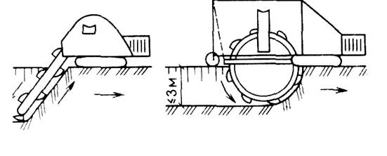
Fig. 9. The development of the soil of multi-domestic excavators A - chain; b - rotary
By the nature of the movement of the working body relative to the direction of movement, the excavators are longitudinal and crossbar. Excavators of the longitudinal draw (chain and rotary) are used for the device trench of small sizes; Excavators of the crossbar - to develop cotlings and trenches of a large cross section, planning slopes, when working in careers. When the trench device, along the route, lay the surface layout with a bulldozer to the width of the multi-loving excavator. Continuous excavators are capable of developing soils I ... III groups that do not contain stumps, stumps and large inclusions.
Development of soil by earthmoving machinery. Earth-and-transport machines for one cycle are developing the soil, move it, unload into the mound or cavalier and return to the bottom of the empty. The main earthmoving machines are screenshots, bulldozers and graders.
Screpets distinguishes high performance. They are used in the development of kittlers and on planning work in soils I ... IV groups. Dense soils before developing scraper pre-loose. The thickness of the soil layer developed in one pass depends on the power of the scraper and is 120 ... 320 mm.
The working bodice is a bucket with a knife device located in the lower part of it, which, when moving, carry out the layer cutting of the soil while moving it into the bucket. Loading the bucket with simultaneous flushing of the soil with a layer with a thickness of 220-550 mm also when the lock is moving.
Screpets are trailed with a bucket capacity of 2.25 ... 10 m3, working in a tractor-tractor-tractor, and self-propelled with a bucket with 8 m3 and more. Self-propelled scrapers are more perfect machines. They have good maneuverability and high movement speed.
The scheme of the scraper depends on the mutual arrangement of the recess and embankments. The simplest is the scheme of work on an ellipse (Fig. 10, a). But in this case, the car makes the turn only in one direction, which leads to uneven wear of the working parts of the scraper. To eliminate this phenomenon, use the operating scheme of the "eight" scraper (Fig. 10.6).
Fig. 10. Scheme of soil development by strokes A-Pouch by ellipse; B - on the eight; B-dual bearing on an ellipse with two embankments; Mr., at two notches; 1-page loading; 2-loaded scraper; 3-section unloading; 4-empty screenshots
This scheme double reduces the number of full scraper turns, which increases its performance.
When alternating embankments and recess, the most effective scheme of the scraper is a dual bearing (Fig. 6.10.V.). The range of transportation of the soil by trailed locks - up to 1000 m, self-propelled - up to 3000 m.
Bulldozers We develop the soil in shallow and extended grooves and reserves to move it into the mound to a distance of up to 100 m. The bulldozers are also collapsed, smoothed and planned soil, cleaned the bottom of the cutlers after excavator development. They are often included in the equipment, providing a complex mechanization of earthworks, leveling the soil delivered by various vehicles.
The development of recesses by a bulldozer lead tiers equal to the thickness of the layer to be removed in one pass. At the same time ensure the work of the bulldozer under the slope.
At the planning works, the soil is used mainly by trench or layers.
In the first case, the tiers in a depth of 400 ... 500 mm are developed by trenches with a width in the dump of the bulldozer, leaving between them untouched ground with strips 400 ... 600 mm (Fig. 11, a). They are cut by a bulldozer last.
Fig. 11. Diagram of the soil engineering bulldozers Trench (A) and layers (b).
In the layer-by-layer method, the soil is developed by layers, on the thickness of the filtered chips in one pass of the bulldozer, sequentially across the entire width of the excavation or its separate part (Fig. 11.6).
With the distance of the soil movement, more than 40 m use a method of development with an intermediate shaft, as well as paired operation of two bulldozers. The smelting in the embankment is layered in the mound, starting with a more remote point from the place of the fence.
Greiders carry out the planning of the territory, the device of slopes of earthworks and extended embankments with a height of up to 1 m, shall be profile roadbed, take off the cuvettes. Dense soils in front of them developing a grader loose by a tractor ripper or plow. The graders are used when moving the soil for small distances.
Full-text search:
Under the management of projects means the area of \u200b\u200bactivity, during which certain goals are determined and achieved, and is also optimized ... Fully \u003e\u003e
Home\u003e Essay\u003e Construction
General provisions
The construction of any buildings and structures causes the need to process soils, which includes their development, movement, laying and sealing. The whole complex of these processes is called earthworks.
The proportion of earthworks in the total volume of construction and installation works is very large and is about 15% at cost and up to 20% by labor intensiveness. Earthworks account for about 10% of all workers employed in construction. The volumes of earthworks are constantly growing and amount to over 15 billion per year. Recycling of such a number of soil is possible only under the condition of complex mechanization and effective technology for the production of work.
One of the important reserves to reduce the volume of earthworks, and consequently, the cost of construction, the use of which is completely dependent on the architect, is to ensure the binding of buildings and the design of the vertical layout, taking into account the terrain.
The decline in the cost and complexity of earthworks should be achieved using rational design solutions that ensure the maximum balance of the necessary recesses and mounds with minimal distances of the soil movement, machine complexes, which minimizes the volume of work performed manually.
Currently, earthworks are mainly carried out by mechanized complexes, and manual development of the soil is provided only in places inaccessible to machines, since the performance of manual labor 20 ... 30 times lower than the mechanized, which significantly affects the total labor costs.
Industry produces various high-performance earthmoving, earthmoving, sealing machines and mechanisms.
The choice of a set of machines and methods of work of work are carried out on the basis of a technical and economic analysis of various options.
Important conditions for further improvement of the technology of earthworks are:
the rational organization of the production of earthworks in the time of year is a reduction in the volume of work performed in winter;
increase the share of the use of high-performance earthmoving machines;
creation and implementation in the production of sets of machines for filling trenches and pita, seals and developing frozen soils.
Types of earth facilities
In industrial and civil construction, earthworks have to be carried out in the device of recovery and trenches under the foundations and underground communications, when eating roads, as well as planning sites.
Recesses and mounds obtained as a result of the development and movement of the soil are called earthworks. They have the following names:
boiler - recess width of more than 3 m and no less width;
trench - a width of less than 3 m and long, multiple times higher than the width;
shurf - deep excavation with small size in the plan;
mound - construction from bulk and compacted soil;
reserve - the removal, from which the ground is taken to build the embankment;
cavalier - Matter formed during the sinking of unnecessary soil, as well as created for its temporary storage.
Earth structures are:
permanent - mounds of roads, dams, dams, irrigation and reclamation channels, water bodies, planning platforms of residential areas, industrial complexes, stadiums, airfields, etc.
temporary - recesses for laying underground communications and devices of foundations, mounds for temporary roads.
Depending on the purpose of the earthen structures, various requirements for steepness and thoroughness of the separations, the degree of compaction and the filtering ability of the soil, its resistance to erosion and other mechanical properties are presented.
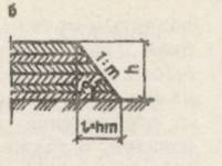
Fig. 1. Elements of Slop: A - notches; B - mound.
To ensure the stability of earth structures (embankments and recesses), they are elevated with slopes, the steepness of which characterizes the ratio of the height H to the lowering L, H / L \u003d 1 / M, where M is the slope coefficient (Fig. 1).
The steepness of the slopes is determined by the construction norms and rules (SNIP III-8-76 "Earth structures") for permanent and temporary earthworks, depending on their depth or height and type of soil. The slopes of the mound of constant structures make more gentlemen than the slopes of the excavation. The coolest slope is allowed when the temporary kittlers and trenches are appliance.
Classification of soils
Soils in the construction production are called rocks that occur in the upper layers of the earth's crust. Mineral components are mineral particles of various chicdoms and organic impurities. By the nature of structural bonds of particles, the soil is divided into two classes:
rock soils where individual particles are configured between themselves, as a result of which the soil has great strength;
unknown soilsconsisting of destroyed rocks. Depending on the particle size, their content and quantity of organic impurities, non-tagged soils are divided into large-grass, sandy, samp, clay, thin, lesible, iba and peat.
Properties and the amount of soil affect the stability of earthworks, the complexity of the development and cost of work.
The choice of the most effective way to develop or strengthen the soil is carried out taking into account its basic properties: density, humidity, filtering coefficient, clutch and dispersion.
Density - Weight of 1 m3 of soil in a natural state (in a dense body). The density of sand and clay soils is 1.6 ... 2.1 t / m3, and rocking non-destructible soils - up to 3.3 tons / m3.
Humidity - The degree of saturation of the soil with water, which characterizes the ratio of the mass of water in the ground to the mass of solid particles of the soil, expressed as a percentage. With humidity up to 5%, the soil is considered dry, 5 ... 30% - wet, and more than 30% are wet.
Filtration coefficient - Indicator of the soil ability to skip (drain) water. It is measured by the amount of water skipped per day and depends on the composition and density of the soil. For sandy soil, this coefficient is in the range of 0.5 ... 75, clay - 0.001 ... 1 m / day.
Clutch - Indicator of the initial resistance of the soil shift. It depends on the type of soil and its humidity and is for sandy soils 3 ... 50 kPa, for clay - 5 ... 200 kPa.
Breakfast - The index of the ability of the soil increase in the amount by reducing the density in its development. This indicator is characterized by a disassembly coefficient. The coefficient of the initial and residual breakdown is distinguished: KR and KO.R.
The initial loosening coefficient is the ratio of the volume of loosen soil to the volume of the soil in the natural state.
For sandy soils of the Kyrgyz Republic is 1.08. ..1.17, sublibious - 1.14 ... 1.28 and clay - 1.24 ... 1.3.
The soil laid in the mound even under the influence of the mass of the overlying layers or the mechanical seal does not reach the volume he occupied before the development.
The ratio of the volume of compacted soil to the volume of the soil to its development characterizes the residual breaking coefficient. For sandy soil, it is 1.01 ... 1,025, loamy - 1.015 ... 1.05 and clay - 1.04 ... 10.9.
The density and grip of the soil basically affect the difficulty of its development. The classification of soils for the difficulty of development is given in Yenir (Collection 2, Vol. 1, section 1, technical part, Table 1 and 2) Taking into account the type of machines used. When developing single-line excavators, the groundwork for the difficulty of development is divided into six groups, multi-discovered and staples - into two groups, and with manual - to seven groups.
In the production of earthworks, it is often necessary to drain and fix the soil using the electric space method or in the temperature effect on the ground when it is thawing and artificial freezing. In these cases, it is necessary to know the electrical conductivity and the thermophysical properties of the soil, which are mainly dependent on the degree of humidity of the soil, but not from its type.
4. Preparatory and auxiliary work when erecting earthworks
The construction of earthen structures requires the implementation of preparatory and auxiliary works. Preparatory work includes: the preparation of the territory, the geodesic breakdown, the provision of drainage and drainage, land gasket.
Supporting works include: the device of temporary fixing of the kittlers and trenches, ensuring waterfront or lowering the level of groundwater, artificially fixing weak soils.
Breakdown of earthen structures It provides for the establishment and consolidation of their locality. Perform breakdown by center drawings tied to the coordinate grid of this site. Breakdown methods depend mainly on the type of structure and method of manufacturing work. There are split works for individual catlers, earthlightened construction structures (roads, channels, dams, etc.), structures with developed in all directions in terms of contours, etc.
The breakdown of the catlovanov is beginning with the removal and consolidation on the terrain with the coating signs of the main centering axes, for which in most cases the main axes of the building are taken: I - I and II-II (Fig. 2, a). Then, around the future, recalled at a distance of 2 ... 3 m from its browing, parallel to the main centering axes, install a pickup, consisting of metal struts or covered wooden pillars and attached boards at an altitude, which ensures the free passage of people. The board should be a thickness of at least 40 mm, have a edged facet to upward, and attached at least three racks. In places of transport passage makes gaps. On the ground with a significant bias, the pickling is suitable for ledge. On the boards, the pickups transfer the main centering axes, and all the other axes of the building are placed, fixing them with nails or feeders and numbers. After the construction of the underground part of the building, the main center axles are transferred to its base.
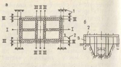
Fig. 2. Schemes for the breakdown of boilers (a) and trenches (b): 1 - Obstruction; 2.- board; 3.- rack
For linearly extended structures, only transverse pickles are arranged, located on direct sections after 50 m, and on rounded - after 20 m. The picking is also suitable on all pickets and points of the profile fractile. Apply metallic inventory (Fig. 2,6).
The altitude breakdown and removal of marks are performed by geometrical leveling from the reperctions of the geodetic center base, which should be at least two.
The correctness of the breakdown is tested by the injection of control polygonometric theodolite and leveling strokes. The error does not have to exceed the breakdown error.
Temporary fastening of the walls of the recess. In the cramped conditions and in the water-saturated soils, the walls of trenches and the catlers have to do vertical, with the installation of temporary mounts. The temporary mount is made of wooden or metal sheets, wooden panels with support racks, shields with spacer frames (Fig. 3).
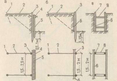
Fig. 3. Fastening the walls with sheets (A), shields with support racks (b), shields with spacer rams (B)
1-anchor bond; 2-delay, 3 reference rack; 4-guide; 5-tongue fencing, 6-papers, 7-stand strut frame, 8-exercise.
The walls of the recess depth of more than 8 m are often fixed using the "Wall in the Ground" method,
The tongue fence is used with water-saturated soils near existing buildings and structures. The spool is immersed before the selection is developed.
In the soils of the natural humidity of the wall of the kittlers and trenches, it is advisable to mount with wooden panels with supporting racks. The shield mount is suitable in the process of recess or after, depending on the degree of ground mobility. The most effective are attachments with inventory spacer plates from metal tubular racks and spacers. They have a relatively small mass, easily assemble and disassembled. The telescopic design of the strut makes it possible to adjust its length, and the presence of a sleeve with a screw cutting allows you to tightly press the shields to the walls of the excavation. The struts with racks are fixed with each other at different heights with the help of pins.
Calculate according to the drawings earths Constructions, as well as ...
Building residential 4-storey 2-section house for 16 apartments
Coursework \u003e\u003e ConstructionFastening weak soils. For execution earths work for construction residential 4-storey, 2-section house .... - 480 p. 7. Yenir. Collection 2. Earthman work. Issue 1. Mechanized and manual earthman work./Gostroy USSR. - M.: Stroyzdat, 1988 ...
Earthman work when planning and developing a construction site
Coursework \u003e\u003e Construction... construction - Bryansk. Start earths work 28.05.2010, Completion earths work ... e2. Earthman work, vol. 1. Mechanized and manual earthman work (Yenir ... Kuznetsov V.G. Complex mechanization earths work. Methodical instructions for coursing ...
Project of production work on the building Car expensive
Tutorial \u003e\u003e TransportRoad work Group work Name work Allowable air temperature, ° C 0 Preparatory, concentrated earthman work, building Bridges, pipes ...
1. General Provisions
The construction of any buildings and structures causes the need to process soils, which includes their development, movement, laying and sealing. The whole complex of these processes is called earthworks.
The proportion of earthworks in the total volume of construction and installation works is very large and is about 15% at cost and up to 20% by labor intensiveness. Earthworks account for about 10% of all workers employed in construction. The volumes of earthworks are constantly growing and amount to over 15 billion per year. Recycling of such a number of soil is possible only under the condition of complex mechanization and effective technology for the production of work.
One of the important reserves to reduce the volume of earthworks, and consequently, the cost of construction, the use of which is completely dependent on the architect, is to ensure the binding of buildings and the design of the vertical layout, taking into account the terrain.
The decline in the cost and complexity of earthworks should be achieved using rational design solutions that ensure the maximum balance of the necessary recesses and mounds with minimal distances of the soil movement, machine complexes, which minimizes the volume of work performed manually.
Currently, earthworks are mainly carried out by mechanized complexes, and manual development of the soil is provided only in places inaccessible to machines, since the performance of manual labor 20 ... 30 times lower than the mechanized, which significantly affects the total labor costs.
Industry produces various high-performance earthmoving, earthmoving, sealing machines and mechanisms.
The choice of a set of machines and methods of work of work are carried out on the basis of a technical and economic analysis of various options.
Important conditions for further improvement of the technology of earthworks are:
· The rational organization of the production of earthworks in the time of year - reducing the volume of work performed in winter;
· Increasing the share of the use of high-performance earthmoving machines;
· Creation and implementation of car sets and kittlers, seals and developing frozen soils in the production of sets of machines.
2. Types of earthworks
In industrial and civil construction, earthworks have to be carried out in the device of recovery and trenches under the foundations and underground communications, when eating roads, as well as planning sites.
Recesses and mounds obtained as a result of the development and movement of the soil are called earthworks. They have the following names:
boiler - recess width of more than 3 m and no less width;
trench - a width of less than 3 m and long, multiple times higher than the width;
shurf - deep excavation with small size in the plan;
mound - construction from bulk and compacted soil;
reserve - the removal, from which the ground is taken to build the embankment;
cavalier - Matter formed during the sinking of unnecessary soil, as well as created for its temporary storage.
Earth structures are:
· Permanent - mounds of roads, dams, dams, irrigation and reclamation channels, reservoirs, planning platforms of residential areas, industrial complexes, stadiums, airfields, etc.
· Temporary - notches for laying underground communications and devices of foundations, mounds for temporary roads.
Depending on the purpose of the earthen structures, various requirements for steepness and thoroughness of the separations, the degree of compaction and the filtering ability of the soil, its resistance to erosion and other mechanical properties are presented.
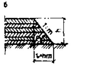
Fig. 1. Elements of Slop: A - notches; B - mound.
To ensure the stability of earth structures (embankments and recesses), they are elevated with slopes, the steepness of which characterizes the ratio of the height H to the lowering L, H / L \u003d 1 / M, where M is the slope coefficient (Fig. 1).
The steepness of the slopes is determined by the construction norms and rules (SNIP III-8-76 "Earth structures") for permanent and temporary earthworks, depending on their depth or height and type of soil. The slopes of the mound of constant structures make more gentlemen than the slopes of the excavation. The coolest slope is allowed when the temporary kittlers and trenches are appliance.
3. Classification of soils
Soils in the construction production are called rocks that occur in the upper layers of the earth's crust. Mineral components are mineral particles of various chicdoms and organic impurities. By the nature of structural bonds of particles, the soil is divided into two classes:
¾ rock soils where individual particles are configured between themselves, as a result of which the soil has great strength;
¾ unknown soilsconsisting of destroyed rocks. Depending on the particle size, their content and quantity of organic impurities, non-tagged soils are divided into large-grass, sandy, samp, clay, thin, lesible, iba and peat.
Properties and the amount of soil affect the stability of earthworks, the complexity of the development and cost of work.
The choice of the most effective way to develop or strengthen the soil is carried out taking into account its basic properties: density, humidity, filtering coefficient, clutch and dispersion.
Density - Weight of 1 m3 of soil in a natural state (in a dense body). The density of sand and clay soils is 1.6 ... 2.1 t / m3, and rocking non-destructible soils - up to 3.3 tons / m3.
Humidity - The degree of saturation of the soil with water, which characterizes the ratio of the mass of water in the ground to the mass of solid particles of the soil, expressed as a percentage. With humidity up to 5%, the soil is considered dry, 5 ... 30% - wet, and more than 30% are wet.
Filtration coefficient - Indicator of the soil ability to skip (drain) water. It is measured by the amount of water skipped per day and depends on the composition and density of the soil. For sandy soil, this coefficient is in the range of 0.5 ... 75, clay - 0.001 ... 1 m / day.
Clutch - Indicator of the initial resistance of the soil shift. It depends on the type of soil and its humidity and is for sandy soils 3 ... 50 kPa, for clay - 5 ... 200 kPa.
Breakfast - The index of the ability of the soil increase in the amount by reducing the density in its development. This indicator is characterized by a disassembly coefficient. The coefficient of the initial and residual breakdown is distinguished: KR and KO.R.
The initial loosening coefficient is the ratio of the volume of loosen soil to the volume of the soil in the natural state.
For sandy soils of the Kyrgyz Republic is 1.08. ..1.17, sublibious - 1.14 ... 1.28 and clay - 1.24 ... 1.3.
The soil laid in the mound even under the influence of the mass of the overlying layers or the mechanical seal does not reach the volume he occupied before the development.
The ratio of the volume of compacted soil to the volume of the soil to its development characterizes the residual breaking coefficient. For sandy soil, it is 1.01 ... 1,025, loamy - 1.015 ... 1.05 and clay - 1.04 ... 10.9.
The density and grip of the soil basically affect the difficulty of its development. The classification of soils for the difficulty of development is given in Yenir (Collection 2, Vol. 1, section 1, technical part, Table 1 and 2) Taking into account the type of machines used. When developing single-line excavators, the groundwork for the difficulty of development is divided into six groups, multi-discovered and staples - into two groups, and with manual - to seven groups.
In the production of earthworks, it is often necessary to drain and fix the soil using the electric space method or in the temperature effect on the ground when it is thawing and artificial freezing. In these cases, it is necessary to know the electrical conductivity and the thermophysical properties of the soil, which are mainly dependent on the degree of humidity of the soil, but not from its type.
4. Preparatory and auxiliary work when erecting earthworks
The construction of earthen structures requires the implementation of preparatory and auxiliary works. TO preparatory work include: Preparation of the territory, geodesic breakdown, provision of drainage and drainage, road strip.
Supporting works include: the device of temporary fixing of the kittlers and trenches, ensuring waterfront or lowering the level of groundwater, artificially fixing weak soils.
Breakdown of earthen structures It provides for the establishment and consolidation of their locality. Perform breakdown by center drawings tied to the coordinate grid of this site. Breakdown methods depend mainly on the type of structure and method of manufacturing work. There are split works for individual catlers, earthlightened construction structures (roads, channels, dams, etc.), structures with developed in all directions in terms of contours, etc.
The breakdown of the catlovanov is beginning with the removal and consolidation on the terrain with the coating signs of the main centering axes, for which in most cases the main axes of the building are taken: I - I and II-II (Fig. 2, a). Then, around the future, recalled at a distance of 2 ... 3 m from its browing, parallel to the main centering axes, install a pickup, consisting of metal struts or covered wooden pillars and attached boards at an altitude, which ensures the free passage of people. The board should be a thickness of at least 40 mm, have a edged facet to upward, and attached at least three racks. In places of transport passage makes gaps. On the ground with a significant bias, the pickling is suitable for ledge. On the boards, the pickups transfer the main centering axes, and all the other axes of the building are placed, fixing them with nails or feeders and numbers. After the construction of the underground part of the building, the main center axles are transferred to its base.
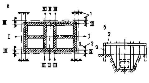
Fig. 2. Schemes for the breakdown of boilers (a) and trenches (b): 1 - Obstruction; 2.- board; 3.- rack
For linearly extended structures, only transverse pickles are arranged, located on direct sections after 50 m, and on rounded - after 20 m. The picking is also suitable on all pickets and points of the profile fractile. Apply metallic inventory (Fig. 2,6).
The altitude breakdown and removal of marks are performed by geometrical leveling from the reperctions of the geodetic center base, which should be at least two.
The correctness of the breakdown is tested by the injection of control polygonometric theodolite and leveling strokes. The error does not have to exceed the breakdown error.
Temporary fastening of the walls of the recess. In the cramped conditions and in the water-saturated soils, the walls of trenches and the catlers have to do vertical, with the installation of temporary mounts. The temporary mount is made of wooden or metal sheets, wooden panels with support racks, shields with spacer frames (Fig. 3).
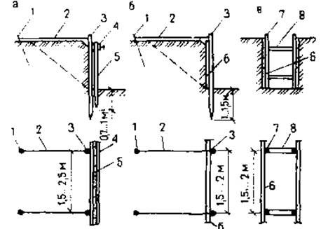
Fig. 3. Fastening the walls with sheets (A), shields with support racks (b), shields with spacer rams (B)
1-anchor bond; 2-delay, 3 reference rack; 4-guide; 5-tongue fencing, 6-papers, 7-stand strut frame, 8-exercise.
The walls of the recess depth of more than 8 m are often fixed using the "Wall in the Ground" method,
The tongue fence is used with water-saturated soils near existing buildings and structures. The spool is immersed before the selection is developed.
In the soils of the natural humidity of the wall of the kittlers and trenches, it is advisable to mount with wooden panels with supporting racks. The shield mount is suitable in the process of recess or after, depending on the degree of ground mobility. The most effective are attachments with inventory spacer plates from metal tubular racks and spacers. They have a relatively small mass, easily assemble and disassembled. The telescopic design of the strut makes it possible to adjust its length, and the presence of a sleeve with a screw cutting allows you to tightly press the shields to the walls of the excavation. The struts with racks are fixed with each other at different heights with the help of pins.
5. Determination of earthworks
The production volumes of the developed soil are determined in a dense body along the volume of the soil with the main production processes and the surface area during preparatory and auxiliary processes (the layout of the slopes, the pusty of the surface, etc.). When designing earth structures, the calculation of the scope of the soil is reduced to the determination of the volumes of different geometric figures limited by even planes. Most often it is necessary to determine the volume of catlers and tranches.
Determination of the volume of the pit. To calculate the volume of the pit, which is a prismatozoic (Fig. 4, a), initially determine its dimensions as follows:
a \u003d a + 0.5 * 2; B \u003d B + 0.5 * 2;
a1 \u003d a + 2nt; B1 \u003d B + 2T,
where and B - the sizes of the parties to the pione, m;
a1 and B1 - the sizes of the sides of the pit on top, m;
A and B - the size of the foundation of PIIIMU, M; 0.5-working gap from the edge of the foundation prior to the beginning of the slope, m;
H - the depth of the pit, calculated as the difference between the average arithmetic mark of the top of the pit in the corners (black - if it is hampered on the planning embankment and red - on the planning recess) and the bottom of the bottom of the bottom, M;
m is the slope rate normed SNIP III-8-76.
The volume of the pit is defined as
VK \u003d H [(2a + A1) B + (2A1 + A) BL] / 6.
The volume of reverse filling of the sinuses is determined as the difference between the volumes of the pit and underground part of the structure (Fig. 4, b).
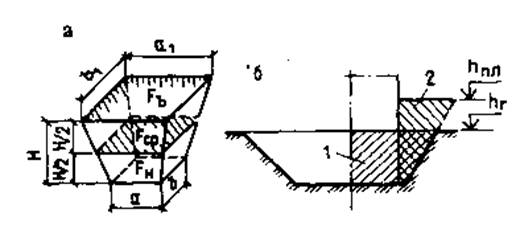
Fig. 4. Scheme for determining the volumes of recovery (A) and backfill (b): 1-recess volume; 2.-volume of backfill
Determination of the volume of trenches and other linearly extended earth structures.It is determined taking into account the longitudinal and transverse profiles of the structure. For this purpose, areas between the profile break points along the bottom of the trench and its surface are distinguished.
For each of these sections, the volume is calculated separately, after which they are summed. The site is considered as a trapezoidal prismatoid (Fig. 5), the approximate volume of which is equal to:
V \u003d (F1 + F2) L / 2 (oversized) or
V \u003d FSR.L (understated),
where F1, F2-area cross-section at the beginning and at the end of the section under consideration, m²;
FSR. - cross-sectional area in the middle of the site under consideration, m2;
L - Length of the site, m.
The exact value of the volume is determined by the Murzo formula:
V \u003d FCP + L,
where H1, H2 is the depth at the beginning and at the end of the plot, m.
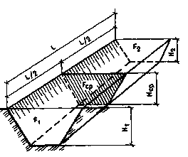
Fig. 5 scheme for determining the volume of trench
Determination of the volumes of soil masses during vertical layout.On the built-in territory, as a rule, planning work related to the cutting of protruding and backing up of the trees. Depending on the volumes and type of the cut of the soil, the distance of its movement, the area relief determine the planning method. There are several methods for determining the volume of work on the vertical layout of the territory. The choice of method depends on the complexity of the relief and the required counting accuracy. The most common methods of four-gone and triangular prisms are the most common.
The essence of these methods is that the entire area on the plan with horizontals is divided into elementary figures, for each of which determine the volume of work, and then summarize them.
The method of tetrahedral prisms. It includes the membership of the area of \u200b\u200bthe site to rectangles or squares with the parties 10 ... 100 m. The calmer the terrain, the larger sizes take the parties of the rectangle. Further calculation will be easier if the rectangles take the same sizes. For all vertices, rectangles are calculated black (local) HF marks - by interpolating the values \u200b\u200bof neighboring horizontals, red (design); HPR - at a given planning mark and existing slope, working marks H - as a difference between red and black marks. The working mark with the "Plus" sign shows the height of the mound, and with the "minus" sign - the depth of the excavation. The calculated marks are recorded next to the vertex according to the scheme shown in Fig. 6.
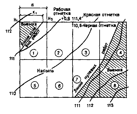
Fig. 6. The scheme of breaking the area in determining the volume of planning works by the method of tetrahedral prisms. Figures in circles - numbers figures
Between the two vertices with working marks of different signs, they find a point in which the working mark is zero. At this point, no earthworks are required. The distance from it to vertices, having the corresponding working marks H1 and H2, is found according to the rule of proportionality of the sides of similar triangles, and H1 and H2 are included in the formula as absolute values:
X1 \u003d ah1 / (h1 + h2),
where X1 is the distance of the zero point from the vertex having a working mark H1, M;
a - the length of the side of the rectangle between the vertices with the working stamps of H1 and H2, m.
By connecting the zero points among themselves, it is obtained by a line of zero works, which is the boundary between the zone of the planning excavation and the planning embankment.
This line dissects individual rectangles on other geometric shapes of various sizes. For each figure, located in a particular zone, determine the volume of embankments and recesses, multiplying the square of the figures to the average worktop. The average working mark is the amount of working markers in the vertices of the considered figure, divided by the number of vertices of this figure. The results of the counting are entered into a statement having the following form:
| Number figures | Recess (-) | Matter (+) | ||||
| F. | HCP. | V. | F. | HCP. | V. | |