Sizing the pit. Big Encyclopedia of Oil and Gas
Foundation pit - this is earthworks with a width of more than 3 m and a length of not less than the width, torn off under the entire building, for the installation of continuous monolithic foundations, driving piles, device basement and basement floors. The volume of work when extracting the pit depends on the geometric dimensions and shape of the pit.
Sizing the pit.
1. The width (a) and length (b) of the pit on the bottom (or along the bottom of the pit) depend on the size of the building, the type and size of the foundation, the distance from the edge of the foundation to the foundation pit, which serves as a workplace for installers and waterproofers.
Figure 1. Sizing the bottom of the pit.
and rear - the width of the building in the axes, b rear - the length of the building in the axes, hk - the depth of the pit, bf - the width of the foundation, hf - the height of the foundation, Lm - the workplace of installers and waterproofers.
So, the width (length) of the pit along the bottom will add up according to formula 1:
![]()
The width and length of the building are determined according to the architectural and planning decision of the building.
The width of the foundation is set according to the source data. For a pile foundation, the width of the foundation is the width grillage. For a continuous slab foundation, the size of the overhang of the foundation from the axis of the building, for example 0.6 m, is taken. reinforced concrete foundation the width is initially assumed to be 1.2 m, but this width may be subject to change in the future.
2. Depth of the pit hk depends on the space-planning solution of the building, the depth of the basement or basement, the type of foundation and is calculated constructively.
Example 1: see figure 2.
For the mark of 0,000 in the building adopted the floor of the first floor. The ground level relative to the zero mark is located at a depth of 0.82 m. The basement depth is 2.4 m, the basement floor is located at -2.62 m relative to the zero mark.
Suppose that reinforced concrete slabs are used as foundations strip foundations (pillows), the height of which, according to GOST 13580-85, is 300 mm. Assume also that the height of the basement floor is 300 mm.
Add the basement floor level mark, the basement floor thickness and the height of the foundation pillows: 2.62 + 0.3 + 0.3 \u003d 3.22 m - the depth of the pit relative to the clean floor level of 0,000.
Because the ground level is below the floor level of the first floor by 0.82 m, then clean pit depth (hк) we get based on the calculation: hк \u003d 3,22-0,82 \u003d 2,4 m

Figure 2. Determining the depth of the foundation pit
So, all the elevations were determined earlier, the height of the foundation was set according to the task (only the height of the precast concrete foundation is taken to be 300 mm).
3. The width (s) and length (d) of the pit on the top.
The dimensions of the pit at the top may coincide with the dimensions of the pit at the bottom (pit with rectangular walls) or the dimensions at the top may be larger than the sizes at the bottom by slope laying values (trapezoidal form of foundation pit; foundation pit with slopes).
Depending on the depth and type of soil in which the work is carried out, pits are with slopes and without them. Slope - the inclined wall of the pit or trench, preventing shedding of soil during construction work. The presence or absence of slopes is determined according to SNiP according to table 1 depending on the height of the pit and the type of soil specified by the initial data.
Page 1
The width of the trench along the bottom with a pipe diameter of up to 700 mm should be 0 3 m more than this diameter, and with a larger diameter it is taken equal to one and a half diameters. When ballasting with loads, the distance between the wall of the trench and the load should not be less than 0 2 m, and the width of the trench along the bottom should not be less than 2 2 diameters.
The width of the trench for steel pipes is taken from the condition of laying them along one pipe and welding the joint at the bottom of the trench.
The width of the trench for prefabricated reinforced concrete and brick collectors depends on how they are laid and sealed. During the construction of brick canals, the outer walls of the canal chair are laid close to the inner walls of the trench. Then the width of the trenches will be equal to the width of the channel to the outer size.
The width of the trench is determined by the number and type of cable lines being laid, the permissible distances between them, as well as the technical data of the excavation mechanism used.
The width of the trench at the bottom mark is 0 3 - 0 5 m, and at the top 0 8 - 2 5 m, depending on the angle of repose of the soil. The length of the trench is determined by the number of electrodes installed. In the case of using coke backfill, it is placed in an even layer with a thickness of 0 1 m along the bottom of the trench. This layer is leveled and rammed.
The width of the trench (at the bottom) for laying one or two cables is 350 mm, and with a larger number of cables it increases by 150 mm for each subsequent cable. When laying the cable in the ground, it is necessary to provide a margin of 3% of the total cable length and arrange it evenly along the entire length, laying it with a snake. When withdrawing armored and unarmored cables to the surface from a trench, it is necessary to protect them from mechanical damage up to a height of 2 m from ground level, and when entering cables from trenches into a building through a protective pipe, measures should be taken to prevent water from entering trenches into the building. Cables laid in the ground are indicated by special signs, fixed on the walls of the nearest buildings or on poles.
The width of the trench at the bottom for cables up to 10 kb is: 350 mm, for one or two cables; 600 mm for three; 650 mm for four. If there are more than five cables, the width of the trench along the bottom increases by 120 - 130 mm for each subsequent cable.
The width of the trench (bottom and without fixing) when laying pipes should be 0 5 m greater than their diameter, if the latter is not more than 0 5 m; when laying pipes in the channel, the width of the trenches is taken to be 0 2 m more than the width of the channel.
The width of the trench (bottom and without fixing) when laying pipes should be 0 5 m greater than their diameter, if the latter is not more than 0 5 m; when laying pipes in the channel, the width of the trenches is taken to be 0 2 m more than the width of the channel. Cast-iron pressure pipes are laid forward with bells (with respect to the street network); the joints are closed up, filling the annular gap with a hemp tarred rope and then the remaining annular space is filled and minted with asbestos-cement mortar.
The width of the trench is determined by the number and type of cables laid and the permissible distance between them. To lay one cable for voltage up to 10 ke, the width of the trench should be 350 mm, with its further increase by 120 - 150 mm for each subsequent cable.
The dimensions of the pits are determined based on the overall dimensions of the structure in terms of its depth, the steepness of the slopes, as well as the accepted methods for performing the basic production processes. It is important to take into account: the construction scheme of the future structure, which determines the movement pattern of cranes and other machines when assembling prefabricated or erecting monolithic structures; delivery and layout of structures in the installation area, installation of formwork, scaffolding and scaffolding. Since in the construction of water supply and sanitation systems, recessed and most often capacitive structures of rectangular or round shape are constructed that actually differ from each other only in their sizes and internal structural elements, then regardless of their purpose and accessory (but taking into account the general dimensions of the structures) identify the following four main schemes for their construction: SchemeI (ring) -crane and vehicles during the construction of the structure move around it along the berm of the pit, not dropping to its bottom; schemeII- mechanisms move along the bottom of the pit outside the structure, along its perimeter; schemeIII - mechanisms in the process of construction of a structure move directly along its bottom; schemeIV provides for the installation of the structure at the same time, that is, in parallel with two cranes, in which the structures of the extreme degrees of the adjacent span of the structure are mounted with the first crane with the movement of it and vehicles along the pit berm, and the structures inside the structure with the second crane moving along the bottom of the structure.
Schemes for determining the size of pits and trenches:
a- pits of small size c. plan (In Soor<15м); b- the same, medium (In Soor\u003e 15 m);
in- the same, large (In sooo, 3\u003e 15 m): g- trenches with vertical walls and fixtures;
d- trapezoidal; from- complex cross-section with combined laying of pipelines
Scheme I usually erects small structures, the width of which in plan or diameter does not exceed 15 m. The dimensions of the pit (width IN to and length Lк) are determined on the basis of the external dimensions of the structure with slight broadening
its bottom on each side for ease of work (Fig. a): Bk \u003d Vsoor + 2b, Lk \u003d Lsoor + 2b, where Scoop, Lsoor - the width and length of the erected structure along the outer perimeter; b - the width of the free space between the bottom of the slope of the excavation and the protruding part of the bottom of the structure (accepted according to the safety conditions and the convenience of work of at least 0.5 m) According to Scheme II, structures of medium dimensions are being erected, the dimensions of which in plan exceed 15 m with a significant depth and a large mass of mounting elements. The dimensions of the pit should be sufficient for the placement of structures, as well as for the passage of cranes and vehicles around them along the bottom of the excavation (Fig. b)and for the layout of prefabricated structures on the front of work:
B K \u003d D H n + (n-l) B 2 + 2B 3; L K \u003d D a n 1 + (n 1 -l) B 2 + 2B 3, where D H - the diameter or size of the structure along the outer perimeter; pand n 1 - the number of structures or sections in one row, respectively, in the transverse and longitudinal directions; IN 2 - distance between structures in the light; IN 3 - broadening of the pit along the bottom for the safe implementation of installation work and traffic; B 3 \u003d\u003d 2 (1 + R), where 1 is the clearance between the moving crane and the structure (or slope of the excavation), m; R- radius of rotation of the crane machine platform.
When constructing structures from monolithic reinforced concrete, the dimensions of the pit are determined by the same formulas, only with the addition of IN to and L K double value 2 b op - the width of the formwork unit or the fastening of stationary formwork and scaffolding at the level of the bottom of the pit). Under Scheme III, large structures are usually built ( in),whose dimensions in the plan are several times greater than 15 m. In this case, the dimensions of the pit are equal: Bk \u003d Vsoor + 2b + B 4, Lk \u003d Lsoor + 2 l 1 where IN 4 - broadening of the pit for the installation of structures of the last section of the structure (pic in);l 1 - broadening of the pit at the ends of the structure for entry and exit of the crane and vehicles (taken equal to 6 .. .7 m and depends on the radius of their rotation); B 4 \u003d 1 · 3 + 2R m + Ba, where B a - the width of the truck base at the body level (size). Under scheme IV, large structures are built at IN soor \u003e 15pm. The dimensions of the pits, since the broadening of their bottom by IN 3 or IN 4 not required, can be determined by the formulas used in scheme I. The dimensions of the pits on top IN to in and B to in determined based on their size down IN to , L to , digging depths H and accepted slope ratios t for appropriate soils. Trench Sizes. The smallest trench width along the bottom of Bt.min (according to SNiPu) should be taken depending on the type and diameter of the pipes being laid, and the method of laying them. The width of the trenches along the bottom with a pipe diameter of over 3.5 m, as well as on curved sections of the route, is set by the project. The width of the trenches with slopes (Fig. e)at the bottom it is taken equal to D + 0.5 m when laying pipelines from individual pipes and D + 0.3 m when laying with lashes. When mounting fixtures (Fig. d)the width of the trench is increased by their thickness. If work of people is necessary in trenches with vertical walls, the smallest distance in the light between the surface of the pipeline (collector) and the walls should be at least 0.7 m. The width of the trench on top is determined by the steepness of its slopes. The depth of the trench depends on the depth of the pipe, which in all cases should be 0.5 m more than the estimated depth of freezing of the soil. The longitudinal slope of the trench is set by the project depending on the purpose of the pipeline. To seal the butt joints of pipes in trenches, pits of the required size are torn off.
a foundation pit is an earthen structure in the form of a excavation with commensurable dimensions in plan, the length does not exceed, as a rule, 10 times the width of the width formed during excavation. Development of excavation technology for excavating excavations incl. in itself: 1) the study of the planning and structural solutions of the underground part of the building being built. 2) designing the pit and determining its main dimensions. 3) calculation of volumes of soil processing and compilation of the balance of earth masses. 4) calculation of the required technical parameters and the selection of earthmoving machines 5) calculation of the need for a vehicle for the removal of excess soil 6) determination of the composition of earthwork and the choice of technology for their implementation. Based on the results of the development of the layout and structural solutions of construction projects, we make the following preliminary decisions. 1. The construction of the underground part of the building will be carried out in an open pit with slopes that ensure their stability. 2. installation and laying works on the device of the building structure of the underground part of the building will be carried out using jib cranes with their arrival on the bottom of the pit in order to minimize the working reach of the crane jib. 3. soil for backfilling of the sinuses will be placed on the berm of the foundation pit parallel to the extreme axes of the building axis 1 and 4. 4. exits to the pit, will be placed between the axes of the building 1,2 and 3,4
Designing the pit and determining its main dimensions.
The dimensions of the pit depend on the dimensions of the building being erected and on the technology for the production of installation and laying works (technology for the erection of building structures). A jib crane will be used for installation and laying works, its work will be carried out with a race on the bottom of the pit. This type of work is better to use since the building is one-story and wide. To reduce poured boom crane.
Excavation design.
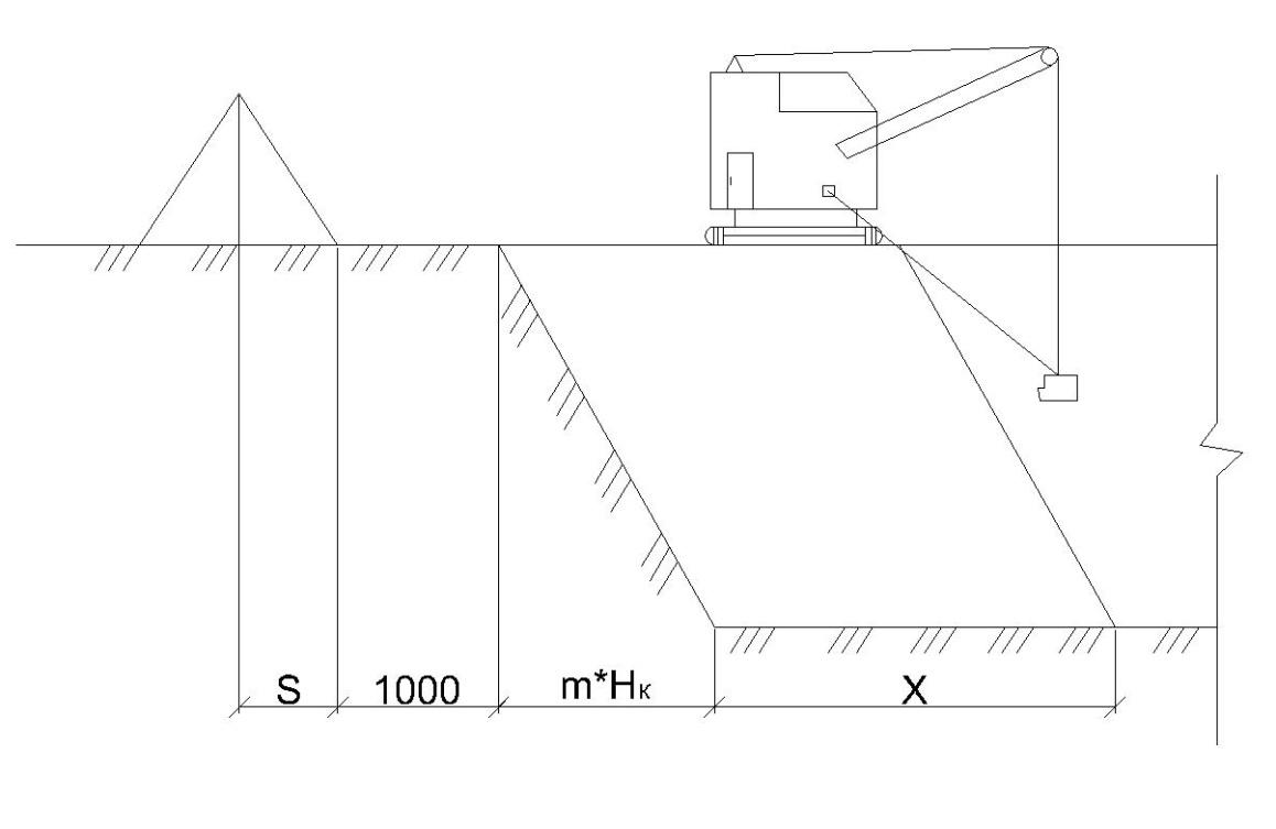
When designing the pit, we arrange at least 2 congresses, their number is selected depending on the shape and size of the building being built. The width of the carriageway of the exit b is taken in the aisles from 3.5 to 4 m, as for single-lane traffic.
b \u003d 4m the steepness of the exit M` \u003d 8-15m, we take M` \u003d 8m. The smaller M`, the smaller the dimensions of the building exits. The distance in the plan from the outer edge of the foundations of the building, to the bottom of the pit in the absence of a ramp is taken to be 0.5 m, from the side of the ramp it is calculated by the formula:
where r is the radius of the clan turntable, taken according to the catalog for cranes
We accept r \u003d 2.5m
s \u003d 1 + 2 * 2.5 + 1 \u003d 7m
Determination of the main dimensions of the pit.
The depth of the pit is equal to the height of the building minus the base.
H K \u003d h + h shchb + h b -h tsok \u003d 4.0 + 0.2 + 0.2-0.8 \u003d 3.6 m
h- height of the underground part according to the task + part of the basement
h shch - thickness of the crushed stone preparation layer
h b - the thickness of the concrete preparation layer
h plinth - plinth height
exit length:
H K * 8 \u003d 3.6 * 8 \u003d 28.8m
(Does not go beyond the construction site.)
The steepness of the slope of the pit
is determined by the ratio of its depth to the laying, is designated as m \u003d 0.5 (SNiP 12 04-2002.2 for sand with a pit depth of not more than 5 m)
Excavation slope pit size:
a \u003d m * H K \u003d 0.5 * 3.6 \u003d 1.8m
Define the dimensions of the pit on the bottom and top:
when placing exits on two opposite sides of the pit
In to n \u003d In c + 2 ∙ a ′ + 2 ∙ in op - the width of the pit on the bottom
L to n \u003d L with + 2 ∙ a + 2 ∙ in op - the length of the pit on the bottom
where: B s and L s - respectively the width and length of the dimension of the structure (building) in
foundation, m;
in op - the width of the formwork used, m
(the value in op in can be taken within 0.3 ... 0.5 m). Accepted in op \u003d 0.5m.
B - size between axles
b - distance from the axis of the foundation to the edge of the foundation
In s (1,2,3,4) \u003d 15 + 0,75 ∙ 2 \u003d 16.5 m.
In k n (1, 4) \u003d 16.5 + 7 + 2 ∙ 0.5 + 7 + 2.4 \u003d 26.9
In k n (2,3) \u003d 16.5 + 7-2.4-2 ∙ 0.75 \u003d 19.6
L - size between the axles
l is the distance from the axis of the foundation to the edge of the foundation
L s (1, 2,3,4) \u003d 78 + 0,75 ∙ 2 \u003d 79.5 m.
L to n (1, 4) \u003d 79.5 + 2 ∙ 2.4 + 2 ∙ 0.5 \u003d 85.3 m.
L to n (2,3) \u003d 79.5 + 2.4-2 ∙ 0.75-2.4 \u003d 78 m.
In to in \u003d In to n + 2 ∙ m ∙ H to - the width of the pit on top
L to in \u003d L to n + 2 ∙ m ∙ H to - the length of the pit on top
where m is an indicator of the steepness of the slope
H to - the depth of the pit
In c in (1.4) \u003d 26.9 + 2 ∙ 1 ∙ 2.4 \u003d 31.7 m.
L k in (1, 4) \u003d 85.3 + 2 ∙ 1 ∙ 2.4 \u003d 90.1 m.
In to in (2,3) \u003d 19.6 m.
L k in (2,3) \u003d 78 m.
3.2. Determination of the volume of earthwork. Earth mass balance.
According to the dimensions defined above, the pit volume will be equal to:
V to \u003d H to / 6, m 3
V c \u003d [(85.3 + 78) (19.6 + 26.9) + (90.1 + 78) (31.7 + 19.6) + (163.3 + 168.1) ∙ (46 , 5 + 51.3)] 2.4 / 6 \u003d 19451.16 m 3
The volume of excavation from two exits:
V c \u003d n c V 1с \u003d n c (m ׳ –m) H to 2/6, m 3,
where: n c - the number of exits to the pit
in c and m ′, respectively, the width and steepness of the exits
V c \u003d 2 (10 –1) 2.4 2/6 \u003d 282 m 3
The amount of backfilling of the sinuses of the structure:
V ps \u003d V to - V pchs + V c, m 3
where: V pchs - the volume of the underground part of the building (structure), m 3
V pchs \u003d 78 ∙ 15 ∙ 2 ∙ 2.4 \u003d 5616
V ps \u003d 19451– 5616+ 282 \u003d 14117
The need for soil for backfilling the sinuses of structures is subject to
coefficient of residual loosening To o.r. , i.e.
V gr. c. \u003d V ps To o.r. , m 3
To o.r. \u003d 100 / (100 + P o.r.),
where P o.r. - indicator of residual loosening of the soil,%, taken according to
ENiR E2-1. P o.r. \u003d 4%
To o.r. \u003d 100 / (100 + 4) \u003d 0.96
V gr. c. \u003d 14117 ∙ 0.96 \u003d 13552
The results obtained are summarized in the table of earth mass balances tab. 3.
Earth mass balance
Table 3
|
Soil development |
Development scope |
Placement of soil and its volume |
Embankment Location |
Soil requirement |
||||
|
Foundation pit |
Blade-15897 |
Sinus backfill | ||||||
|
Transport means- |
Backfill exits | |||||||
![]() coefficient of residual loosening of the soil;
coefficient of residual loosening of the soil;
![]() coefficient of initial loosening of soil
coefficient of initial loosening of soil
The choice of technical means.
Technological design includes a reasonable choice of mechanisms for the production of the main types of earth processes, determining the composition of these processes with the calculation of their complexity.
We substantiate the choice of the following basic mechanisms:
Machines for excavation;
Machines for transporting soil from the pit.
Calculation of technical parameters and the choice of excavators:
When choosing an excavator, two main criteria are taken into account: the construction being developed and the proposed type of excavator. Depending on the volume of soil in the pit, the capacity of the excavator bucket is selected, and then its brand.
Since the excavator is used to tear the pit, and the pit is of considerable size, it is preferable to use an excavator with a working dragline for such work. Depending on the total amount of soil development, ∑Vв \u003d 19733m³ for tearing the pit according to the recommendations, we take the capacity of the excavator bucket 1.6 m³.
Pit depth 4.0 m.
. The scheme of operation of the dragline excavator when extracting the pit
The required values \u200b\u200bof R to and R in are calculated by the sinking at which the excavator is working
will sweep. They are determined from the condition that
R to + R at ≥ V s / 0.8,
where In s - the width of the extreme calculated face, m
Considering also that the R to the excavator is on average 15 ... 25% more than R in, tentatively we get:
R k \u003d 0.7 V s, m and R b \u003d 0.57 V s, m
The width of the bottom face B3 is the sum of the width of the excavation zone b s, slope m H k, half the width of the soil dump on the berm b holes and the permissible distance b (taken at least 1 m) from the bottom of the dump to the edge of the pit:
In s \u003d b s + m H to + b + b holes, m
When the dumps are located along all four sides of the pit, the values \u200b\u200bof b holes and b s are determined by the formulas:
b holes \u003d √ (b s H to K a.s.), m
b s \u003d V holes / (ℓ s. H to), m
where ℓ s is taken approximately equal to half the perimeter of the pit along its
bottom and top (ℓ s \u003d L to n + B to n + L to b + B to c).
ℓ s \u003d 163.3 + 46.5 + 168.1 + 51.3 \u003d 429.2 m.
b s \u003d 13823 / (429.2 2.4) \u003d 13.4 m.
b holes \u003d √ (13.4 2.4 1.15) \u003d 6 - half the width of the blade
In s \u003d 13.4 + 1 2.4 + 1 + 6 \u003d 22.8 m.
Cutting radius R k \u003d 0.7 ∙ 22.8 \u003d 15.96 m.
Unloading radius R in \u003d 0.57 ∙ 22.8 \u003d 13 m.
According to the values \u200b\u200bfrom the ENiRa table, we accept an excavator with a dragline working body: brands EO-7111 (E-2503), EO-7111C, (E-2505); capacity of bucket with teeth 1.5 m³; electric control; boom length 25m; the largest digging radius of 27.4 m; the greatest digging depth: with a side passage of 14 m, with an end passage of 20.5 m; the largest unloading radius of 23.8 m; the highest unloading height is 15.9 m; power 160 kW (218hp); excavator weight 94t; time standards per 100 m³ of soil with loading in the vehicle 0.78 and 0.67 in the excavation.
Calculation of the need for dump trucks for the removal of excess soil
To transport excess soil from the excavation when excavating the pit, we use dump trucks in the amount necessary to ensure the smooth operation of the driving machine - the excavator.
Because excavator bucket capacity, average transport density of excess soil, select a dump truck with a lifting capacity
We determine the required number of dump trucks N auto based on the conditions, as mentioned above, to ensure uninterrupted operation of the excavator, i.e.:
N aut \u003d T c / τ p,
where: T c - the duration of the working cycle of one dump truck, min;
τ p - the duration of the soil loading by the excavator into the body of one dump truck,
The duration of the truck’s duty cycle consists of the duration of its installation for loading τ unitary enterprise, the duration of loading the soil into the body τ p, the duration of the run to the place of unloading and the return idle distance, etc., the duration of the installation for unloading τ ur, the duration of unloading τ p and the duration of technological breaks during the flight (maneuvering, passing oncoming vehicles at the roundabout, etc.) τ m, i.e.:
T c \u003d τ yn + τ p + τ pr + τ ur + τ p + τ m, min
(When performing the calculations, it should be accepted: τ yn \u003d 0.3 ... 0.5 min; τ ur \u003d 0.5 ... 1.0 min;
τ p \u003d 1.0 ... 2.0 min and τ m \u003d 1.0 ... 3.0 min.)
Accept:
τ yn \u003d 0.5 min;
τ ur \u003d 1 min;
τ p \u003d 2 min;
τ m \u003d 3 min.
The duration of the truck to the place of unloading and vice versa can be approximately determined by the formulas:
τ CR \u003d 2 L Tr 60 / υ cf, min, or τ CR \u003d L Tr 60 / υ gr + L Tr 60 / υ cold, min,
where: L Tr - the range of transportation of soil, km;
υ Wed, υ gr and υ Hall - the truck speed is average, respectively, in loaded
condition and at idle run, km / h.
(In the calculations, you can take: υ cf \u003d 35 ... 40 km / h; υ gr \u003d 30 ... 35 km / h and υ cold \u003d 45 ... 50 km / h.)
υ avg \u003d 40 km / h;
υ gr \u003d 30 km / h;
υ cold \u003d 50 km / h.
τ ol \u003d 2 1.5 60/40 \u003d 4.5
The duration of the excavator for loading soil into the body of one
dump truck is determined by the formula:
τ p \u003d 0.6 V aut N mash.vr, min,
where: V av - soil volume in the body of a loaded dump truck, m 3;
N mash.vr - the norm of machine time for the development of 100 m 3 of soil with loading in
vehicle, mash · h (accepted by ENiR E2-1-7 depending on
type of excavator used, its bucket capacity and difficulty group
soil development). N mash.vr \u003d 0,84
The amount of soil loaded into the body of one dump truck is determined by
V aut \u003d V bucket n ek.K K n / K a.s. , m 3,
where: n ec.k - the number of whole excavator soil buckets loaded into the body
one dump truck;
To n - the coefficient of actual filling of the excavator bucket
loose soil (assumed equal to 1.1 ... 1.4). Take K n \u003d 1.4
The number of whole excavator soil buckets loaded into the body of one
dump truck, is according to the formula (with rounding to the nearest whole number):
n ec.k \u003d Q aut / (V bucket γ gr. K n / K a.s.),
where γ gr is the density of the soil, t / m 3 (taken according to table 1 ENiR or
any other reference data). We take for sand γ gr \u003d 2.65 t / m 3
n ec.k \u003d 12 / (1.5 2.65. 1.4 / 1.15) \u003d 3
V avt \u003d 1.6 3 1.4 / 1.15 \u003d 5.84 m 3.
τ p \u003d 0.6 5.84 0.84 \u003d 2.9 min.
T c \u003d 0.5+ 2.9 +4.5+ 1 + 2 + 3 \u003d 13.9 min
n auth ≥ T c / τ ol \u003d 13.9 / 4.5 \u003d 3.1
We accept the number of dump trucks naut \u003d 4
Determination of the composition, technology and scope of work for the excavation of the pit
When developing an excavation pit by an excavator, it is impossible to reach the design level, so as not to destroy the bottom of the pit. The shortage of soil is 20 cm, therefore, cleaning the bottom of the boilers is required.
This cleaning is carried out in 2 stages: cleaning to a depth of 0.15 m by a bulldozer, and by 0.05 m manually by diggers.
The bottom area of \u200b\u200bthe pit is S d \u003d 3125 m 2, which means the scope of work on cleaning with a bulldozer V \u003d 2241.28 ∙ 0.15 \u003d 336.2 m 3. We accept the bulldozer DZ-28 (D-533) based on the T-130 tractor (ENiR E2-1-22).


