Development of fastening the vertical walls of the pit. Securing slopes of temporary excavations
During earthworks in cramped conditions, as well as in the presence of groundwater, quicksand and other difficult hydrogeological conditions, when it is not possible to provide the required laying of slopes, it is necessary to fix pits and trenches.
The permissible depth of excavation, i.e., the maximum (critical) depth, at which the slope of the cohesive soil is held in a vertical position without fixing the walls, is determined by calculation. Approximate values \u200b\u200bof the critical depths of the excavations arranged with vertical walls: 1.0 m in bulk, sandy and gravelly soils of natural humidity; 1.25 m - in sandy loam; 1.5 - in loams and clays; 2.0 - in particularly dense non-rocky soils.
The need for fastenings is established by the project. The device for fastening the vertical walls of pits and trenches requires significant manual labor, therefore, fastening is done only when it is economically feasible or when it is not possible to slope.
Depending on the type of soil, the width and depth of the excavations and the service life, various types of fasteners are used. Temporary support can be made in the form of a wooden or metal dowel, wooden boards with supporting stands, boards with spacer frames. The design of any mount includes clogging made of boards, beams or shields that directly perceive ground pressure. To keep the pickup in an upright position, runs, struts and other elements are used. There are horizontal mounts when planks or planks of pickup are wound horizontally behind the racks, and vertical when planks of planks are mounted vertically and fastened by horizontal girders with spacers.
For narrow trenches with a depth of 2-4 m in dry soils, a horizontal-frame fastening is used, consisting of uprights, horizontal boards or plank (solid and non-continuous) shields and struts, pressing boards or boards to the walls of the trench. Spacers are installed along the length of the trench at a distance of 1.5-1.7 m from one another and in height after 0.6-0.7 m.
Vertical mount is most often used if mounts are placed in one row. The pick-up is continuous if the soils are unstable and have high humidity, or with gaps (clearances) if sufficiently stable cohesive soils of normal humidity are attached. In difficult hydrogeological conditions, when there are strongly water-saturated spreading soils, a solid fence made of wooden or metal sheet pile is used.
There are three types of mounts to hold the pickup in an upright position: spacer, cantilever, and strut. The spacer mount is the most common due to its ease of assembly. At the same time, the racks are freely installed on the bottom of the recess and pressed against the fence with horizontal struts installed at several levels according to calculation. The width of the notch with spacer is limited. The spacer mount is installed in the following sequence: after snatching a section of the trench, two frames are lowered into it and placed on the bottom after 2 m from each other, temporarily unfastened by guy wires, then horizontal boards or boards are placed on top of the gap between the frame racks simultaneously on both walls, after which push the spacer frames all the way.
In those cases where the possibility of installing struts is excluded (for example, when developing wide pits), anchor or strut mounts are used. The strut mounts consist of plank boards installed along the slopes of the struts that are held by struts, and stops hammered at the base of the struts. However, such a fastening, with all its structural simplicity, suffers from several drawbacks: this fastening constrains the work inside the pit, in addition, clogging of persistent anchors leads to a violation of the soil structure at the bottom of the pit.
Cantilever mounts are characterized by the fact that the racks (wooden piles) are held by pinching the lower part in the ground. Racks, piles, rails, rolled steel, pipes, etc., are driven into the bottom of the recess to a depth of 2.2-3.3 m. The horizontal pick-up boards are either located behind the racks or placed between the I-beam shelves. The cantilever fastening is carried out in this order: along the trenches broken on the ground, racks with an estimated step to a depth below the bottom of the future foundation pit are hammered. After that, develop the soil. If the soil is unstable, horizontal pick-up elements are installed simultaneously as the trench deepens. At the same time, each subsequent board is brought down from below under the previously installed one - they are grown up. In sufficiently stable soils that are capable of holding a vertical slope for at least a short time, trenches are torn off in sections of 3-4 m long to the design depth, and the pick-up boards are set by lowering from the top - by building. Widely used mount from a wooden or steel sheet pile; with undivided fastening, the racks are located after a certain step, and in the grooved they are hammered without an interval.
Cantilever non-abutment fastening is used for pits and wide trenches up to 4.7 m deep. If necessary, tearing deeper pits is done by additional fastening of the upper part of the racks with anchors. An anchor consists of one or two hammered anchors and braces. Anchors should be hammered to a depth of about 3 m and at a considerable distance from the edge (equal to about one and a half depths of excavation) in order to position them outside the destruction prism. The distance between the anchors is determined by calculation. The disadvantage of this method is that the arrangement of anchors requires a significant free area along the recess and, in addition, guy wires interfere with the work in this area, so sometimes guy wires are arranged in trenches 0.5 m deep that are open for this purpose.
When constructing deep pits with a sheet piling, first around the perimeter of the future foundation pit a steel sheet pile is hammered 4-5 m below the bottom, then anchors are installed, and then the soil is torn off. Hanging fasteners are most often used for fastening pits of rectangular cross-section with a depth of 2-5 m, depending on the purpose; they have horizontal elements that play the role of resistant runs, which are suspended from a support frame placed on the surface of the recess.
Fig. 6.:
a - console; b - anchor; c - cantilevered; g - spacer; d - strut; e - outboard; 1 - shields (boards); 2 - racks (piles); 3 - anchors; 4 - struts; 5 - struts; 6 - stops (anchors); 7 - support; 8 - ring
In loose and unstable soils, spacers or frame mountings from plates and bars are placed. In viscous soils and with a strong influx of water clogging sheet pile walls from boards or bars, reinforced with spacers, are clogged. On the surface of the earth, a wooden block frame is laid according to the size of the well, and then from the outside of the frame beams, close to them, clog boards 1.5-2 m long with some slope and dig a foundation pit under the protection of clogged boards. After deepening by 1-1.5 m, a second of the same frame is installed at the bottom of the well and the second row of boards is hammered. In the same manner, they continue to work until the required depth is reached (Fig. 6).
The development of trenches with vertical walls by rotary and trench excavators in cohesive soils (loams, clays) is allowed without fastening to a depth of not more than 3 m. Work on the construction of foundations, laying of utility networks, etc. in trenches with vertical walls without fastenings should be carried out immediately after excavation to prevent it from shedding or creeping.
© 2000 - 2009 Oleg V. website ™
During the production of earthworks, a number of side works have to be performed, without which development is impossible. These works are called auxiliary.
The most common auxiliary works during earthworks include:
- device for fastening trenches and pits;
- drainage (removal of water from pits);
- arrangement of temporary roads, entrances to the face and exits from the face for the carriage of soil during its development.
We must always strive to ensure that all auxiliary work is carried out by special workers and that the production of auxiliary work does not delay the main work and does not interfere with them.
Excavation fixing device
As already mentioned in, not every soil can hold vertical slopes when digging it. The value of the required slope of the pit is equal to the value of the angle of natural slope of the soil. This slope is the most reliable.
However, digging pits and trenches at great depths with gentle slopes is considered not economical, as it causes a significant amount of excessive excavation. Even at shallow depths, natural slopes are sometimes impossible to implement, for example, if buildings are located nearby. In those cases when the bottom of the pit or trench is under water, free slopes are completely unacceptable, since they are not protected from soaking with water and destruction.
That is how much in most cases, when arranging pits and trenches, it is necessary to arrange various kinds of temporary fastenings. In addition, as indicated above, the particular type of fasteners (sheet piling) serves to reduce the influx of groundwater into the pits.
Fastening trenches and pits with wooden struts
The simplest fastenings of the walls of pits and trenches up to 2 m deep are arranged as follows.
Along the walls of the trenches, 4 boards with a thickness of 50 mm are laid with spacers between them, placed 1.5-2 m across the length of the trenches (Fig. 38);

Spacers are made of short logs or pipes 10-12 cm thick. This type of fastening is used for dense, dry soils that can hold a vertical slope for some time and are not washed away by rain (thick clay, dense loam). In this case, slopes can be either vertical or with a slight slope (1/10).
At more significant depths (up to 4 m) for dry soils, which give local creep after a short period of time after the passage, the so-called horizontal fastening is arranged. It is arranged like this: for the entire depth of the pit, a number of thrust posts are installed from boards up to 6 cm thick or plates at a distance of 2 to 3 m, depending on the depth of the pit (Fig. 39). For these racks, a fence is laid from horizontal rows of boards 4-5 cm thick, open or completely, depending on the ground. To hold the racks in place put wooden or steel struts. The spacers should have a length slightly larger than the distance between the opposing walls. When setting the spacers, this circumstance makes it possible to “start” the spacers with blows of a sledgehammer or hammer, and thereby tightly press the racks and the fence to the walls of the foundation pit or trench.
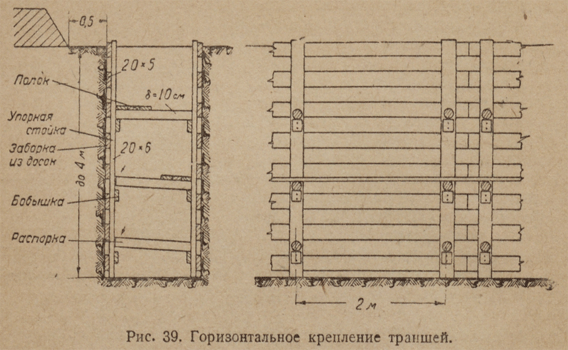
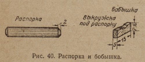
In order to prevent the spacers from falling (Fig. 40), shorts (bosses) from scraps of boards 4-5 cm thick are laid under their ends. Shorties are nailed to the posts with 125 mm nails.
The distance between the spacers in height depends on the depth of the trench. With increasing depth, the pressure of the soil on the fasteners increases, so the spacers are placed below more often than at the top, namely: above - after 1, 2 m and below - after 0.9 m in height. The upper horizontal board is placed slightly above the edge of the trench so that soil from the edge does not crumble into the trench. For transfer of soil shelves from boards are placed on struts.
For loose and wet soils, as well as for crumbling soils, vertical fastening is used, which differs from horizontal in that the horizontal boards in it are replaced by vertical ones, and the racks by horizontal clamping bars. The pressure bars are bursting with struts from the knurl, forming spacer or pressure frames (Fig. 41).

Clamping frames with vertical mounting to a depth of 3 m are arranged from half-edged boards 6 cm thick, and the spacers are made from knurled plates or plates. With a depth of up to 6 m, the thickness of the pressure boards, as well as the spacer, should be increased to 10 cm.
The upper clamping frame must have, in addition to the inner board, an outer board 6 cm thick. This board cuts into the wall of the trench to its full thickness.
The distance in height between the individual clamping frames from the boards is 0.7 - 1.0 m, and with frames from plates and bars - 1.0 - 1.4 m.
With a depth of up to 5.0 m, the number of spacers for each frame of boards with a length of 6.5 m is set to 4 pcs., With a greater depth - 5 pcs.
Both with vertical and horizontal fastening, the walls of the trenches should be vertical. With inclined walls, spacers under the pressure of the earth can jump up.
The lower clamping bars and the struts of the fastenings of the water and sewer trenches should be located so that there is a gap between them and the bottom of the trench sufficient for unhindered pipe laying.
Often there are cases (weak soil, the presence of water) when, before the start of digging, it is necessary to mount devices. In these cases, the mounts are more complex.
These mounts include:
Bottomhole mount
In small but deep pits and pits, the so-called downhole fastening is used (Fig. 42).

It is arranged as follows: on the surface of the earth at the location of the pit or pit, a horizontal block frame is laid to the size of the pit. this frame buries into the ground flush, after the frame a number of boards are clogged slightly obliquely. Then digging a foundation pit under the protection of educated clogged boards the walls. When the excavation approaches the lower ends of the forgotten boards, a second frame is laid between them. In order for the upper frame not to fall down as the soil is developed, shorties from the bars, gradually lengthened, are substituted under it. When the second frame is installed, between it and the upper frame, bars are installed that support the upper frame. After that, another row of slightly inclined boards is driven along the outer edge of the lower frame. Between the upper and lower rows of the fence, wedges of greater stability of the upper fence are clogged.
Fastening pits with piles with a wooden fence between them
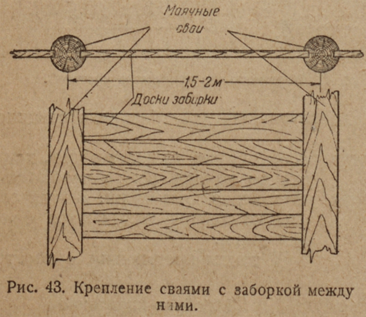
Pit fastening with piles with a wooden fence is used for weak soils that do not allow digging a pit to full depth. In addition, often the installation of cross struts when attaching the pit is undesirable, since it complicates the work in the pit. With a large pit width or its complex form, the spacers are generally impossible to deliver. Therefore, in all such cases, resort to the mounting device piles with a wooden block between them. This type of fastening consists in the following: before the start of digging, wooden and sometimes steel (iron) piles, the so-called lighthouse piles, are driven into the ground at a distance of 1.5-2 m from each other, depending on the depth of the pit (Fig. 43) ; between these piles, as the recess deepens from the side of the slope, separate fastening boards are laid. Piles are driven to a depth slightly greater than the depth of the pit, so that until the pile is dug, the pile remains stable enough. To enhance the stability of lighthouse piles, their upper ends are anchored in a slope or propped by struts, abutting the latter in the pile driven up at the bottom of the foundation pit.
Pit fastenings with piles with a fence can also be arranged in previously dug pits, if it is undesirable to have spacers in the pit, and the soil allows digging without previously installed fasteners.
Securing with sheet piling
To fix pits in soils saturated with water (slurry and quicksand), the so-called sheet piling is used. The tongue-and-groove fence consists of a continuous row of vertically mounted tongue-and-groove pipes or boards (in which a groove is grooved in one edge and a tongue in the other), pressed against the walls of the trench or foundation pit by horizontal frames with spacers (Fig. 44). All that has been said about the spacers in the vertical fastening applies entirely to the sheet piling, namely, when the sheet piling is first, the sheet piling is hammered, and then the trench is excavated with the gradual installation of the spacer frames; in a vertical fastener, a trench or foundation pit is first excavated, and then a fastener is installed, which is gradually lowered down as the soil is further developed. The tongue and groove boards are driven to a depth somewhat greater (by 0.2-0.5 m) of the depth of the trench or pit, so that after the end of digging their lower ends could not be shifted by the pressure of the soil.
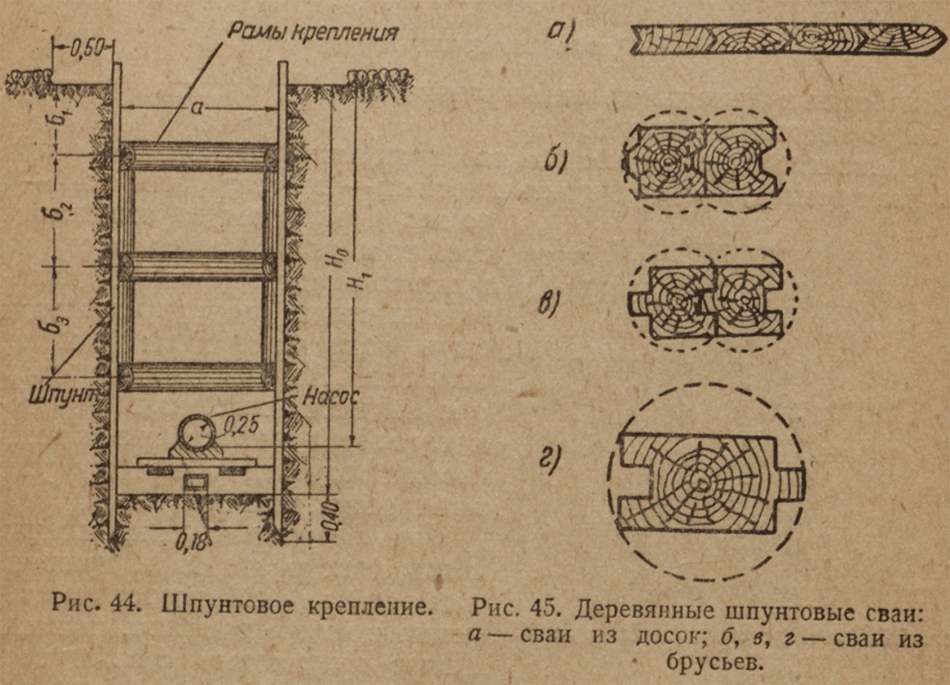
Wooden tongue is made of boards 6-7 cm thick or of 10x20 cm boards (Fig. 45). In each sheet pile (pile) a ridge and a groove are arranged. When driving piles, the crest of one enters the groove of the other. The lower end of the pile is pitched in the form of a wedge with an acute angle from the groove side. With such a flange, the piles are tightly adjacent to each other during driving, which is very important for wet soils, when water seeps under pressure from slots in loose tongues. Sheet piles should be made from raw, freshly cut wood. If they are made of wood, which had already been lying in the air for some time, then they must be put into water for 10-15 days before being driven in order for them to swell. This is done later, that the sheet pile row, clogged from dried piles, swells in wet soil and, due to the increase in pile volume, the row is curved; individual piles turn out, forming cracks, and the row becomes unusable. work on driving piles begins with the installation exactly along the line of the future row of so-called lighthouse piles 2 m apart (Fig. 43).
These piles are hammered in the first place, and frame bars are attached to them on both sides. In the intervals between the lighthouse piles and the frame bars serving as guides, the remaining piles of the sheet pile are driven. Each subsequent pile should be adjacent to the already clogged groove, and the crest should remain free, otherwise the grooves will become heavily clogged with earth, and it will be difficult to achieve a dense row. Hammering is carried out with a mechanical pile driver, and with a shallow depth and weak soil it can also be done manually with wooden broads.
Dismantling the dowel sheet piling mounts
Dismantling of fastenings should be made, starting from the bottom, as the trenches are filled up.
Horizontal fastenings are disassembled on one board with soft soils, and with very dense - no more than 3-4 boards. In this case, the vertical racks are filed down to the desired height. Before filing racks struts should be moved above the place of sawing. Rearrangement of the struts is carried out as follows: first, a new strut is installed on top of the saw, and then the lower one is already knocked out.

With vertical fastening and dowels, the spacers and clamping bars are removed gradually as they are filled up, starting from the bottom: sheet piles and vertical boards are pulled out at the end of the filling with the lever (Fig. 46). In this case, the engagement of piles is done according to one of the methods shown in Fig. 47.

Dismantling the fastenings in piles with a wooden fence is done by gradually sawing as filling boards of the fence are filled up, starting from the bottom; take out the fence one board at a time. Piles are removed after the end of the backfill in the same way as when disassembling sheet piles.
At the moment, steel fences are used: Larsen sheet pile, steel pipes with a diameter of from 159 to 426 mm.
Arranged in dry and low moisture resistant soils.
If the height of the pit is h to ≤5 m, then the laying of the slope (ratio h to / b) is determined by the tables depending on the type of soil.
If the height h to\u003e 5 m, then the calculation of the steepness of the slope is necessary.
Such pits are the simplest, but at the same time, the volume of earthwork increases sharply, especially with deep pits. In addition, in the natural conditions of the city, a passage of a foundation pit with a natural slope is far from always possible (closely located buildings)
2.2.B B foundation pits with vertical walls
can be: - with fastening
Without mount
Without fastening it is allowed only in dry and weakly moist stable soils for a short period. The depth of such pits should not exceed:
in sand up to 0.5 m
in sandy loam up to 1.0 m
in loams and clays up to 3 m
The design of the pit mounts is selected depending on the following conditions:
excavation depth;
soil properties;
fastening service life.
Depending on these conditions, the following mounting structures are selected:
mortgage fastenings;
anchor or strut mounts;
sheet piling.
2.2.V. Mortgage Mounts
Arrange at a pit depth of 2 ... 4 m in dry and low-moisture soils (Fig. 14.2 a, b). A mortgage mount consists of racks, struts and horizontal boards (pick-ups), which lead behind the racks from below as the pit or trench deepens, and the racks are gradually replaced with longer ones by carefully unfastening them with struts.
Fig. 14.2. Fastening the vertical walls of the recesses:
a, b - mortgage; c - anchor; g - strut; 1 - rack; 2 - boards; 3 - spacer; 4 - pile; 5 - screed; 6 - strut
A more convenient fastening that does not require replacing the racks as the recess deepens, consists of I-steel beams previously hammered into the ground, boards are gradually laid over the shelves of which.
2.2.G. Anchor and strut mounts
Arrange in those cases when the possibility of installing spacers is excluded (wide foundation pit, also if the spacers interfere with the construction of the foundation).
For device anchor (Fig. 14.2 c) of fasteners along the pit wall, inclined piles are driven in, which are connected by anchor rods to the fastening posts.
In the strut mount (Fig. 14.2 g), the walls are held by struts that transmit shear forces to the stop clogged from their base.
2.2.D. Sheet Piling
They are used for fastening the vertical walls of the pit at a depth of more than 4 meters, as well as at any depth, but at a groundwater level above the bottom of the pit.
Sheet piling consists of separate elements (tongue and groove), which are immersed in the soil even before the excavation of the foundation pit and form a continuous wall preventing the soil from sliding and penetrating water into the foundation pit.
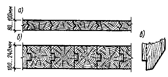
Fig. 14.3. Wooden sheet piling:
a - from the boards; b - from the bars; in - the lower end of the wood tongue
Sheet piles can be made from:
→ Wooden sheet pile fencing is used for fastening shallow pits (3 ... 5 m) (Fig. 14.3) can be:
Plank (thickness up to 8 ... 10cm)
Cobbled (t from 10 to 24 cm)
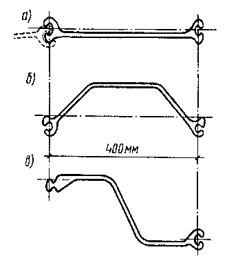
Fig. 14.4. Rolled steel sheet pile profiles:
a - flat; b - trough; in -Z-shaped
The length of sheet piles is determined by the depth of their immersion, but, as a rule, does not exceed 8 m, since a longer one is not expensive and scarce.
To completely close the tongues, they are provided with a crest or groove, and the lower end is made with one-sided sharpening, due to which the immersed tongue and groove is pressed against the already immersed one, which makes the wall more dense.
Additional compaction of the tongue and groove is also facilitated by the gradual swelling of the wood in the water.
Wooden sheet piling is distinguished by ease of manufacture, however, there are limitations to its use:
The impossibility of driving dowels into dense soils;
Short length of sheet piles (6 ... 8 m);
And relatively low strength.
→ Metal the tongue is used at a depth of more than 5 ... 6 m. Due to its design (Fig. 14.4), it has great strength and rigidity.
It consists of a rolling profile l \u003d 8 ... 24 m.
Flat;
Trough; ) at large bending moments
Z-shaped
The connection between the tongues vertically is carried out using castles". The design of the locks provides a tight and durable connection of tongues between them. The remaining gaps in the locks are quickly filled and the metal sheet pile wall becomes almost waterproof.
Reinforced concrete the tongue is used in the construction of embankments, berths and hydraulic structures, or in those cases when the tongue is later used as part of the structure.
Reinforced sheet pile
Continuous reinforced concrete row of piles (driven or bored)
Permitted row of piles in clay soils.
Sheet piling designs:
Without fastenings (cantilever);
With spacer mount;
With soil anchors.

Fig. 14.5. Sheet piling schemes:
and - console; b - with spacer; in - with anchor fastening; 1 - sheet pile wall; 2 - spacer; 3 - strapping; 4 - anchor pile; 5 - anchor rod.
The use of spacer and anchor-type fasteners increases the stability of the sheet pile wall, reduces the bending moments and its horizontal displacements, which makes the walls easier.


