The steepness of the slopes of earthworks. Installation of slopes of earthworks
Sustainability earthworks.
Ensuring the sustainability of earthworks is an essential requirement
by presentation to them. To ensure it, earthen structures are erected with slopes of the necessary steepness. The steepness of the slope of the excavation or embankment depends mainly on the angle of natural slope of the soil. It is taken depending on the depth of the excavation or the height of the embankment, the properties of the soil, their moisture content, the nature of the structures (permanent
yannye or temporary) and other factors. The greatest permissible steepness of slopes
pits and trenches up to 5 m deep, torn off in non-rocky soils above the groundwater level (GWP) or in soils drained using artificial water reduction regulated by SNiP (Table 1).
Table 1. The greatest steepness of the slopes.
Angle between | Angle between | Angle between | |||||
direction | Steepness | direction | Steepness | direction | Steepness |
||
slope and mountain | slope and mountain | slope and mountain |
|||||
zonal | zonal | zonal |
|||||
With a depth of excavation, m, to | |||||||
Bulk | |||||||
Sandy and gra | |||||||
wipe wet | |||||||
ny (insatiable |
|||||||
Clayey: | |||||||
loam | |||||||
Lѐss and lѐsso | |||||||
Moraine: | |||||||
sandy | |||||||
sandy |
|||||||
loamy |
|||||||
When bedding various types of soils (except vegetative), the slope slope for all layers is assigned to weaker soil (with less steepness). For excavation of excavations with a depth of more than 5 m, the steepness of the slope is calculated based on the values \u200b\u200bof the angle of internal friction () and specific soil adhesion (C) taking into account the load on the slope berm. Roughly the steepness of the slope of such excavations in non-moistened soils for average values \u200b\u200bof () and (C) can be taken according to table 2. If necessary, fragments of the grooves below the groundwater level where there will be irrigated soils, the steepness and slopes are taken according to table 3.

Technology of construction processes. Lecture 5.3
Table 2. Estimated maximum allowable slope steepness.
Soil group | With a depth of excavation, m | |||||
Sand (wet non- | ||||||
full) |
||||||
Loam | ||||||
Heavy loam, clay | ||||||
Table 3. Permissible slope steepness in flooded soils.
With a depth of excavation, m |
|||
fine-grained | |||
medium and coarse | |||
Loam | |||
Gravel and pebble (gravel | |||
and pebbles over 40%) | |||
Loose rock | |||
However, it is not always possible to extract pits or trenches with inclined slopes of the necessary steepness to ensure their stability. This, in particular, can happen when extracting excavations in cramped urban areas and then you have to tear them off vertical slopes. To prevent the collapse of the vertical walls, it is necessary to arrange their temporary fastening. It should be borne in mind that without fastenings of the vertical walls of trenches and pits located above the GW, it is allowed at a depth of no more than: in sandy and coarse soil - 1 m; in sandy loam - 1.25 m; in loams and clays (except very strong) - 1.5 m; in very strong loam and clay - 2 m.
Methods and designs of fastenings of vertical walls of foundation pits and trans
necks depend on their depth and size, physical and hydrogeological properties of soils, the presence of dynamic loads at the edges of the excavation (on machines and mechanisms) and the accepted methods for subsequent work (installation building structurespipes, etc.).
Depending on the design solution, the following types of fasteners are distinguished: expansion, cantilever, cantilever-expansion, cantilever-anchor, strut (Fig. 1a). The type of fastening is chosen depending on the purpose and dimensions of the excavation, soil properties, the magnitude of the influx of groundwater and the conditions of work.
By the nature of the design and the degree of turnover, the fastening can be inventory and stationary (from individual elements), solid or with spaces.
Spacersmost common. They are used for trenches up to 3 m deep and consist of shields (solid or with clearances), racks (or girders), sliding screw struts or frames. In fig. 1b shows an inventory version of the mount. This mount consists of wooden panels 2 x 0.5 m, vertical

but connected by beams 80 x 150 mm, metal posts from pipes with a diameter of 70 mm with holes for attaching expandable telescopic struts. Walls are fastened immediately after fragments of the trench.
Figure 1. Fastening the vertical walls of the recesses: a - diagrams of the types of structural solutions for fastening the walls of trenches and pits: I - spacer; II - console; III - console spacer; IV - console-anchor; V - strut: 1 - shields; 2 - racks (piles); 3 - anchors; 4 - struts; 5 - struts; 6 - emphasis; b - inventory spacer
fastening: 1 - metal racks; 2 - corner; 3 - sharpening; 4 - shields; 5 - struts of a telescopic structure; 6 - a bolt; in - console type: 1 - racks; 2 - shields and plates; g - cantilever-expansion type of fastening: 1 - I-beams; 2 - supporting steel corners; 3 - wooden struts; 4 - boards of the enclosing fastening element (pick-up); d - console-anchor type: 1 - racks; 2 - pickup; 3 - pile anchor; 4 - filling; 5 - cords; e - sheet piling with internal anchoring: 1 - sheet piling; 2 - beams; 3 - thrust; 4 - anchors.
Cantilever (Fig. 1c) and cantilevered (Fig. 1d) fastenings are used at depths of 3 m in weak water-saturated soils. The structural elements of the fasteners of this type are: metal racks, piles, continuous pick-up from the boards and struts between the racks.
Cantilever Anchor fasteners (Fig. 1e), unlike cantilevers, have anchors consisting of anchors and cords to the uprights. Anchors are usually installed from the edge at a distance of at least 1.5 h (where h is the depth of the excavation), and their number is determined by calculation.
Sheet Pilingwalls are a type of cantilever fencing and are arranged with deep pits, large lateral soil pressure, difficult hydrogeological conditions. Sheet piling is a continuous wall of steel or wooden sheet piles pre-immersed in the ground with locking joints. There are three options for the execution of sheet piling: cantilever, spacer and anchor (Fig. 1e).
Strut mountsthey are used to fasten the walls of the pit and consist of pick-up, strut, strut, lay and persistent anchor. Mounts of this type make it difficult to work in the pit and therefore are rarely used.
Types and purpose of earthworks. The main properties of soils
Theme 4. Earthworks
The construction of networks and structures of water supply and sanitation systems is associated with the need to carry out large volumes earthworks.
Earthworks are work on the development of soil in excavations, its transportation (movement) and laying in embankments. Excavations and embankments are earthworks (Fig. 4.1), which, depending on their purpose and service life, can be permanent and temporary. Permanent earthworks - dams, dams, canals, reservoirs, sludge collectors, etc. - are intended for long-term operation. Temporary earthworks are arranged as a necessary element for subsequent construction and installation works. These include pits and trenches. Excavations are called excavations, the width of which differs little from the length, and trenches are excavations having small cross-sectional dimensions and a large length.
Reserves and cavaliers also belong to earthworks. Reserves are the excavations from which soil is taken to fill the embankment, and cavaliers are embankments formed during the filling of unnecessary soil, for example, for temporary storage, which is then used again to fill the trenches or sinuses of foundation pits.
Since earthworks are arranged in or out of soils, when designing works, it is necessary to take into account their main properties: density, humidity, water permeability, porosity, angle of repose and internal friction; mechanical properties - strength, deformability, hardness, ductility, resistance to shear, erosion, loosening, compressibility, etc.
Depending on the difficulty of development, all soils are divided into groups (see SNB section 8), which should be taken into account when choosing and determining the productivity of mechanisms and workers.
Ensuring the sustainability of earthworks is an essential requirement for them. To ensure it, earthen structures are erected with slopes of the necessary steepness. Steepness
Fig. 4.1 - Types of earthworks: a, b - trenches with vertical walls and with slopes; c - dam; g - dam; d - channel in the embankment; e - foundation pit; g - a system of pits for the foundations of the columns of the structure; h - foundation pit for the construction; and - underground workings (for adits, pipes, sewers, tunnels); to - the site; l - recess for the lowering well; m - borehole; n - half-half-half-mound; o - underwater trench; 1 - bottom (trench, channel, foundation pit, lowering well); 2 - the side wall of the trench; 3 - side slope (channel, road excavation, foundation pit, embankment, dam, dam); 4 - edge; 5 - berm; 6 - sole; 7 - drainage ditch
the slope of a recess or embankment depends mainly on the angle of repose of the soil. It is taken depending on the depth of the excavation or height of the embankment, soil properties, their moisture content, the nature of the structure (permanent or temporary) and other factors. The greatest permissible steepness of slopes of foundation pits and trenches up to 5 m deep, torn off in rocky soils above the groundwater level or in soils drained by artificial dewatering, is established by SNiP III - 4 - 80 *. When bedding various types of soils (except vegetative), the slope slope for all layers is assigned to weaker soil (with less steepness).
For excavation of excavations with a depth of more than 5 m, the slope steepness is established based on the values \u200b\u200bof the angle of internal friction (φ) and specific soil adhesion (s) taking into account the load on the slope berm. However, when excavating excavations in cramped urban areas or on the territory of industrial enterprises sometimes you have to perform them with vertical walls.
To prevent the collapse of the vertical walls, it is necessary to arrange their temporary fastening. It should be borne in mind that without fastenings of the vertical walls of trenches and pits located above the water treatment, it is allowed with a depth of not more than, m:
in sandy and coarse soil 1
in sandy loam 1.25
in loams and clays (except very strong) 1.5
in very strong loam and clay 2
The fastening of vertical walls is mandatory when excavation is carried out in cramped production conditions, a fragment of deep pits and in highly saturated soils.
The methods and constructions of fastening the vertical walls of pits and trenches depend on their depth and size, physical and hydrogeological properties of soils, the presence of dynamic loads at the edges of the excavation (from machines and mechanisms), and the accepted methods for subsequent work (installation of building structures, pipes, etc. ) Excavations with vertical walls are carried out in accordance with Manual P17-02 to SNB 5.01.01-99. Design and installation of retaining walls and pit mounts.
Depending on the design solution, the following types of fasteners are distinguished: spacer, cantilever, cantilever-spacer, cantilever-anchor, strut (Fig. 4.2).

Fig. 4.2 - Fastening the vertical walls of the recesses:
a - diagrams of the types of constructive solutions for fastening the walls of the trench and pits I - spacer, II - cantilever, III - cantilever-spacer, IV - cantilever-anchor, V - strut; 1 - shields, 2 - racks (piles), 3 - anchors, 4 - struts, 5 - struts, 6 - stops; b - inventory spacer mount: 1 - metal racks, 2 - corner, 3 - pointed, 4 - shields, 5 - spacers of telescopic design, 6 - bolt; in - console type: 1 - racks, 2 - boards or plates; d - cantilevered type of fastening: 1 - I-beams, 2 - supporting steel corners, 3 - wooden struts, 4 - boards of the securing element of fastening (pickup); d - cantilever-anchor type: 1 - racks, 2 - pick-up, 3 - pile-anchor, 4 - filling, 5 - strands; e - sheet piling with internal anchoring: 1 - sheet piling, 2 - beams, 3 - rods, 4 - anchors
By the nature of the design and the degree of turnover, the fastening can be inventory and stationary (from individual elements), solid or with spaces.
Sheet piling walls are a type of cantilever fencing and are arranged with deep pits, large lateral pressure of the soil, difficult hydrogeological conditions. Sheet piling is a continuous wall of steel or wooden sheet piles pre-immersed in the ground with locking joints. There are three options for the execution of sheet piling: cantilever, spacer and anchor (Fig. 4.2, e).
Brace fasteners are used to fasten the walls of the pit and consist of pickup, stand, strut, lay and persistent anchor. Mounts of this type make it difficult to work in the pit and therefore are rarely used.
The main elements of an open pit, pit or trench without mining are: side - l; ledge height - H; ledge form; slope angle - a; steepness (Fig. 7.1). Slope collapse occurs most often along the AC line, located at an angle Θ to the horizon. The ABC volume is called the collapse prism. The collapse prism is held in equilibrium by the friction forces applied in the shear plane. Before developing trenches and pits, it is necessary to determine the steepness of the slopes in advance, ensuring the safety of the work, taking into account the depth of the trench or pit, and choose the method of forming the slopes. Digging pits and trenches with slopes without fastenings in non-rocky soils above the groundwater level (taking into account capillary rise) or in soils drained using artificial water reduction is allowed in compliance with the standard depth of excavation and steepness of the slopes.
Before opening pits and trenches without slopes, regardless of the type of soil, by calculation it is necessary to determine their maximum safe depth, which ensures the stability of vertical walls. The methodology for calculating the safe depth of pits and trenches without slopes is as follows:
1. Calculate the critical height of the vertical wall of the pit (trench) by the formula:
where H is the critical height of the vertical wall, m; C - soil adhesion, t / m2; γ - volume weight soil t / m3; φ is the angle in internal friction
2. Determine the maximum depth of the pit or trenches with a vertical wall, enter the safety factor, taken equal to 1.25:
N etc. \u003d N q / 1.25,
where N pr - the maximum height of the vertical wall, m
The depth of development of pits and trenches with vertical walls without fastenings is established in accordance with DBN A.3.2.2-2009 and is no more than 1 m in bulk, sandy, coarse soil; 1.25 m in sandy loam, 1.5 m in clay. When designing pits and trenches deeper than 5m, it is necessary to calculate the stability of slopes. According to DBN A.3.2.2-2009, the movement, installation and operation of machines near excavations with loose slopes is allowed only outside the collapse prism at a distance established by the project. If there are no solutions in the PPR, the smallest distance to the nearest machine supports is selected according to the table. 4.4. With a excavation depth of less than 5 m, the smallest permissible distance from superstructure (the end of the sleepers, caterpillars, wheels) to the base of the slope is determined by an approximate estimate of the rear edge of the collapse prism using the formula:
l n \u003d 1,2ah +1,
where h is the depth of the excavation, m, and a is the slope laying coefficient, which is taken according to the table. 5.2.
Characteristics of the ground
→ Earthworks
Ensuring the sustainability of earthworks
The stability of earthworks is called their ability to maintain the design shape and size and is due to the equilibrium of the masses under the influence of external and internal forces. Stability depends on the angle of repose of the soil, which is formed by the plane of the slope with the horizontal plane of the soil surface. The angle of repose is determined empirically.
The steepness of the slopes of the embankment or excavation is characterized by the ratio of the height of the slope N to its laying or the tangent of the slope angle to the horizon
(Fig. & 1. 1).
The greatest steepness of the slopes depends on the height of the embankment or the depth of the excavation, soil characteristics (angle of internal friction, adhesion, humidity) and the condition of the work (Fig. 3.2),
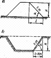
Fig. 3.1. Slope Elements
o -fill; b - recesses; I-slope height; 1-projection of the slope on a horizontal plane; and the steepness of the slope
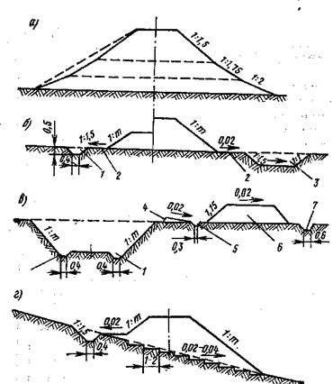
Fig. 3.2. Cross profiles subgrade
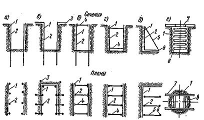
Fig. 3.3. Schematic diagrams of types of fasteners
a - console; b - anchor; c - cantilevered; g - spacer; d - tray; e - outboard; 1 - shields (boards); 2 racks (piles); 3 - anchors; 4 - struts; 5 - struts; 6 - stops (anchors); 7-support; 8 - ring
Methods of fastening slopes of temporary excavations. When conducting earthwork on the territory of existing enterprises in cramped conditions or in the presence of groundwater, quicksand and other difficult hydrogeological conditions, it is necessary to attach trenches and pits. The need for fastenings is established by the project; the device for fastening the vertical walls of trenches and pits requires significant manual labor, therefore, fastening is done only when it is economically feasible or when it is not possible to slope.
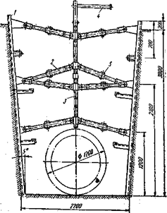
Fig. 3.4. Articulated Screws
Depending on the type of soil, the width and depth of the excavations and the service life, various types of fasteners are used. For narrow trenches with a depth of 2-4 m in dry soils, a horizontal-frame fastening is used, consisting of racks, horizontal boards or plank (solid and non-continuous) shields and struts, pressing boards or shields to the walls of the trench. Spacers are installed along the length of the trench at a distance of 1.5-1.7 m from one another and in height after 0.6--0.7 m.
In those cases where the possibility of installing struts is excluded (when developing wide pits), anchor or strut mounts are used.
To install anchor fasteners along the walls of the foundation pit, the racks are hammered to a depth of 0.5-1 m, from the top they are pulled by anchor rods in the form of two plates attached to an inclined pile, and shields or a plank wall are installed behind the racks.
The strut mounts consist of plank boards installed along the slopes of the struts that are held by struts, and stops hammered at the base of the struts.
Cantilever-spacer mountings are characterized in that the posts (piles) are held mainly by pinching their lower part, clogged into the bottom of the recess. The most widely used mount is a wooden or steel sheet pile. With non-stop fastening, the racks are located after a certain step, and in the tongue and groove they are hammered without an interval. As a dowel, steel profiles can be used.
When anchoring the racks in the upper part, in addition to jamming, they are also fixed with anchors. Unlike anchor fastening, for cantilever-wide jamming, the racks are mounted at the top with struts.
Suspended fasteners have horizontal elements that play the role of resistant runs, which are suspended from a support frame placed on the surface of the recess.
This type of fastening is most often used for fastening pits of rectangular section with a depth of 2-5 m, depending on the purpose.
In loose and unstable soils, spacers or frame mountings from plates and beams are placed (Fig. Sh.Z).
In viscous soils and with a strong influx of water clogging sheet pile walls from boards or beams are clogged, reinforced with spacers. On the surface of the earth, according to the size of the well, a wooden block frame is laid, and then on the outside of the frame bars, close to them, clog boards 1.5-2 m long with some inclination and under protection clogged boards dig a pit. After deepening by 1 - 1.5 m at the bottom of the well, a second same frame is installed and a second row of boards is hammered.
In the same manner, work is continued until the required depth is reached.
The fastening of the vertical walls of trenches up to 3 m deep should, as a rule, be inventory (Fig. W.4). Shields are usually installed vertically and burst with inventory metal spacers. Shields with slots are installed in cohesive soils of natural humidity, and solid shields are used in soils with high humidity.
The need to fasten the vertical walls of trenches and pits or to develop them with slopes is justified by the project, depending on the depth, condition of groundwater and other local conditions.
The standards provide for the development in certain cases of trenches and pits with vertical walls without fastening in the absence of groundwater, in soils of natural humidity. The depth of excavation without fastening should not exceed: in sandy and gravelly soils - 1 m, in sandy loam - 1.25; in loams and clays - 1.5 m; in especially dense non-rocky soils-2 m.
The development of trenches with vertical walls by rotary and trench excavators in cohesive soils (loams, clays) is allowed without fastening to a depth of not more than 3 m.
Work on the construction of foundations, laying engineering networks, etc. in trenches with vertical walls without fastenings should be carried out immediately after excavation in order to avoid its crumbling or creeping.
When digging deeper trenches and pits without fastenings under the indicated conditions, it is necessary to arrange slopes, the steepness of which is determined by SNiP.

