Works on the construction of the subgrade. Thematic selection of the device of the roadbed of roads. Earthworks
link to the page
MINISTRY OF TRANSPORT OF THE RUSSIAN FEDERATION
FEDERAL ROAD AGENCY
FEDERAL STATE UNITARY
ENTERPRISE "INFORMATION CENTER
ON ROADS »
CAR ROADS
Road and bridge conditions, traffic volumes and failure statistics. . Using this data, transport planners, engineers, environmentalists, landscape architects, soil scientists and other specialists identify trends that determine what and how to build.
- What are the environmental concerns?
- What utilities will be affected by the project?
- How can this project be created for the community?
EARTHWEAR DEVICE
CAR ROADS
TOPIC SELECTION
Moscow 2005
Extraction
6. EARTH CANVAS
6.1. The subgrade should be designed taking into account the category of road, type pavement, the height of the embankment and the depth of the excavation, the properties of the soils used in the subgrade, the conditions for the construction of the subgrade, the natural conditions of the construction area and the peculiarities of the engineering and geological conditions of the construction site, experience in operating roads in the area, based on ensuring the required strength, stability and stability as yourself subgrade, and pavement at the lowest cost at the stages of construction and operation, as well as the maximum conservation of valuable land and the least damage to the environment.
The diesel tax is 15 cents per gallon. The federal share of gas taxes is transferred to the federal government, which distributes it under many programs. Until recently, Michigan received only 5 cents for every dollar in gas taxes sent to Washington.
An overview of the area is the second step. Recently, global positioning systems, laser surveys and other technologies have accelerated the process and improved accuracy. Projects are influenced by many factors, including. The location, landscape and soil properties, drainage possibilities, traffic volume, the ratio of cars to trucks and buses, possible further development in the area, environmental impacts or nearby residents. 
Leveling bumps and filling gaps create a surface that will support the road for decades. The center of the road should be above the edges so that the water flows into the storm sewer pipes. Drainage is a critical element, as improper drainage will significantly reduce the life expectancy of the new sidewalk. All this work must undergo rigorous checks before the project can continue. To complete earthworks the contractor places gravel in 12-inch layers on the road. Workers moisturize and compact each layer. Layers are added and compacted until the pavement reaches the height required during design.
- First, the contractor builds embankments using cuts and fillings.
- Then the grader or bulldozer levels the screened dirt.
- Sifted dirt is sprayed with water and compacted to maximum density.
- At this point, the contactor establishes a sewer and sewer.
6.2. The subgrade includes the following elements:
the upper part of the subgrade (working layer);
embankment body (with sloping parts);
base of the embankment (see reference appendix 3);
excavation base;
sloping parts of the excavation;
devices for surface drainage;
devices for lowering or removing groundwater (drainage);
In this analysis, planners and engineers study. 
At a construction site, workers scatter and compact hot mix on the road surface. The finishing machine vibrates and cuts it to the required height. To prevent cracks, workers cut joints between concrete slabs. At each joint, wicker baskets and steel dowels are connected. This allows the plates to expand and contract with temperature. Slabs can slide side to side along dowels, but not up and down.
- Asphalt uses bitumen, petroleum products to glue sand and gravel.
- This mixture is heated to about 300 degrees in an asphalt plant.
- Concrete uses cement and water as an adhesive between sand and crushed rock.
- Workers place concrete in steel molds called molds.
supporting and protective geotechnical devices and structures designed to protect the subgrade from dangerous geological processes (erosion, abrasion, mudflows, avalanches, landslides, etc.).
6.3. The natural conditions of the construction area are characterized by a combination of weather and climate factors, taking into account the division of the territory Russian Federation on road climatic zones in accordance with table. 20.
Testers use seismological equipment to measure the vibrations of the new sidewalk. This is too much vibration, the contractor must grind the pavement to ensure a smooth surface. Another drainage test using permanent pavement marking. . Finally, it's time to remove the barrels and return the motorway to the motorway. Another section of the Michigan Highway is ready to serve communities and businesses for years to come.
Starting on the Ontario border in the Riviera-Bodetta, it runs along the northern bank of the St. Lawrence River through Montreal, Bertierville, Trois-Rivieres and Quebec, among others. From there, he sets off for Saguenay and bypasses Lac Saint-Jean through Tadusac, Saguenay, Roberval, Dolbo-Mistasini and Alma among others.
Table 20
|
Road climatic zones |
Approximate geographical boundaries and a brief description of the climatic zones |
|
North of the line Monchegorsk - Ponoi - Nes - Oshkurya - Sukhaya - Tunguska - Kansk - state border - Birobidzhan - De-Kastri. Includes geographic zones of the tundra, forest-tundra and the northeastern part of the forest zone with permafrost distribution |
|
|
From the border of zone I to the line Lviv - Zhytomyr - Tula - Gorky - Ustinov - Kyshtym - Tomsk - Kansk to the state border. Includes geographic area of \u200b\u200bforests with excessive soil moisture. |
|
|
From the border of zone II to the line Chisinau - Kirovograd - Belgorod - Kuibyshev - Magnitogorsk - Omsk - Biysk - Turan. Includes forest-steppe climate zone with significant soil moisture in some years. |
|
|
From the border of the III zone to the line Dzhulfa - Stepanakert - Buinaksk - Kizlyar - Volgograd, then passes southward up to 200 km from the line Uralsk - Aktyubinsk - Karaganda and to the northern coast of Lake Balkhash. Includes geographic steppe zone with insufficient soil moisture |
|
|
Located southwest of the border of zone IV. Includes desert and desert-steppe geographic areas with an arid climate and saline distribution |
|
|
Notes: 1. The Kuban and the western part of the North Caucasus should be attributed to the III road-climatic zone. 2. When designing road sections in the border zones when substantiating with data on soil-hydrological and soil conditions, as well as on the basis of the practice of roads in the area, it is allowed to make design decisions for the adjacent (northern or southern) zone. 3. In mountainous areas, climatic zones should be determined taking into account the high-altitude location of design objects, taking into account natural conditions at a given height. |
|
Peculiarities of the engineering and geological conditions of the site should be determined by the type of terrain according to the conditions of moistening the upper thickness of the soil and the nature of the surface runoff (Table 1 of mandatory Appendix 2), the properties and conditions of the occurrence of soils within the thickness taken into account when designing, geological, hydrological and permafrost conditions and processes, including the impact of technogenic factors (taking into account the development of the territory), geomorphological features (topography), etc.
According to the moisture conditions of the upper soil stratum, three types of terrain are distinguished:
1st — dry patches;
2nd — moist areas with excessive moisture in certain periods of the year;
3rd - wet areas with constant excess moisture.
6.4. When designing the subgrade, standard or individual solutions should be applied, including standard solutions with individual reference. Individual solutions, as well as individual binding of standard solutions should be applied with appropriate justifications:
for embankments with a slope of more than 12 m;
for embankments in areas of temporary flooding, as well as at the intersection of permanent water bodies and watercourses;
for embankments erected on swamps with a depth of more than 4 m with peeling or in the presence of transverse slopes of the swamp bottom more than 1:10;
for embankments constructed on weak bases (see paragraph 6.24);
when used in embankments of soils of high humidity;
when the surface of the coating rises above the calculated water level less than specified in clause 6.10;
when using interlayers of geotextile materials;
when using special interlayers (heat insulating, waterproofing, draining, capillary, reinforcing, etc.) to regulate the water-thermal regime of the upper part of the subgrade, as well as special transverse profiles;
during the construction of embankments on subsiding soils;
for excavations with a slope height of more than 12 m in non-rocky soils and more than 16 m in rocky soils under favorable engineering and geological conditions;
for excavations in layered strata having a slope of the layers towards the roadway;
for excavations revealing aquifers or having an aquifer at the base, as well as in clay soils with a consistency coefficient of more than 0.5;
for excavations with a slope height of more than 6 m in dusty soils in areas of excessive moisture, as well as in clay soils and rocky softened soils that lose strength and stability in slopes under the influence of weather and climate factors;
for excavation in swellable soils when adverse conditions moisturizing;
for embankments and excavations constructed in difficult geotechnical conditions: on slopes steeper than 1: 3, in areas with the presence or possibility of the development of landslide phenomena, ravines, karst, landslides, screes, mudflows, snow avalanches, ice, permafrost, etc. P.;
during the construction of the subgrade using explosions or hydromechanization;
when designing periodically flooded roads at the intersection of watercourses;
when applying heat-insulating layers in areas of permafrost.
Individually, it is also necessary to design drainage, drainage, supporting, protective and other structures that ensure the stability of the subgrade in difficult conditions, as well as sections of the interface of the subgrade with bridges and overpasses.
Extraction
EARTH CONSTRUCTION
4.44. The replacement of soft soil at the base of the embankment should be carried out on type I swamps with mechanical, explosive or hydraulic removal.
4.45. Boring should be carried out, as a rule, in winter with advance preparation and maintenance of tracks for moving the excavator and transporting the soil.
The peat embankment should be constructed, as a rule, using the “on its own” method with soil transportation along the embankment being erected and the soil being moved forward with a bulldozer.
4.46. Landing of the embankment on a solid foundation in type II and III swamps must be carried out by extruding peat by the weight of the embankment. To facilitate extrusion, peat should be loosened mechanically or explosively, peat bins should be arranged (trenches along the bottom of the embankment), the embankment should be filled with a narrow front (overload method), and vibration and shock loads should be applied.
The embankment should be erected immediately to its full design height.
4.47. During the construction of embankments using compressible soils at their base, the required thickness of the fill should be provided.
When applying the method of temporary loading, the soil from the loading layer after reaching a predetermined draft of the embankment should be used for filling in another area, the embankment should be erected evenly over its entire width.
4.48. Vertical sand drains used to accelerate settlement and hardening the base should be arranged with a special set of equipment, in which either the vibro-pressing pile loader or an excavator with a loader equipped with a special working body in the form of a casing with a drop-down tip is used as the main machine.
For the installation of vertical flat drains from textile and other tape drainage materials, special equipment or adaptations to the machine for immersing vertical sandy drains should be used, which ensure the fastening and feeding of the tape into the casing from the spool and cutting at the desired level.
Drainage slots should be filled with sandy soil as they are constructed.
4.49. When filling the embankment on a weak foundation according to a specially established mode (preliminary consolidation method), each subsequent layer is arranged after the foundation soil has reached a strength sufficient to absorb the additional load.
In the process of consolidation of the base, it is necessary to monitor the settlement of the embankment in order to clarify the volume of refilling or removal of excess soil and assess the possibility of coating.
4.50. When installing in the base of the subgrade, layers of geotextiles should be stitched or glued together. To skip construction machines, the canvases are covered with a layer of at least 0.3 m.
In the presence of stumps, humps, indentations, water on the surface of the base of the embankment, before laying geotextiles, a sand leveling layer should be poured, the thickness of which should be equal to the value of the irregularities.
Anchoring of paintings in the sloping parts of the subgrade should be done by wrapping the free ends of the paintings with a length of 1.5 - 2.0 m around the edge of the soil layer, sprinkled on the canvas. Wrapped ends should be covered with the next highest soil layer.
4.54. When compacting easily eroded and softened coarse soil, the moisture content of small fractions should not be higher than 1.2 optimal.
4.55. Protective layers of clay soil on the slopes should be arranged during the construction of the main part of the embankment.
4.56. When using coarse-grained soils, prone to rapid soaking, during construction, measures should be taken to prevent their excessive moisture from rain or surface runoff, overlapping with waterproof layers and arranging a construction drainage.
EARTH CONSTRUCTION ON SALTED SOILS
4.57. The device subgrade on saline soils with a high level of groundwater must be produced at a time when their moisture content meets the requirements of table. 1.
4.58. The upper loose layer of saline soil, oversaturated with salts, and salt crusts with a thickness of more than 3 cm should be removed from the surface of the reserves and the base of the embankment before erection.
4.59. For the construction of embankments on saline soils with a high level of groundwater and a depth of reserves of not more than 0.5 - 0.6 m, bulldozers and graders should be used. The use of grader elevators for the construction of embankments on salt marshes is allowed if the groundwater level is not closer than 1 m from the surface of the earth.
The filling of the embankment from the imported soil on wet salt marshes should be done using the “on your own” method.
EARTH CONSTRUCTION IN SAND DESERT
4.60. The subgrade in sandy deserts should be erected, as a rule, in the winter-spring period.
4.61. The construction of embankments in moving sand dunes by transversely moving sand from roadside lanes to a distance of 30 m should be carried out with bulldozers equipped with dumps with enlarged side walls.
4.62. When erecting embankments on salt marshes covered with small sand dunes, with close ground waters, it is allowed to use bulldozers when moving sand to a distance of 100 m, with the arrangement of intermediate shafts.
4.63. When building roads in the sands covered with vegetation, it is necessary to take measures against its damage, terrain disturbance and loosening of the sand surface.
4.64. The device of the protective layer and the strengthening of the slopes should be carried out after the construction of the embankment of sand. Protective layers of sand, reinforced with cementitious materials, must be arranged in accordance with the rules for strengthening soils, as a rule, by mixing directly on the subgrade.
The protective layer on the subgrade should be laid according to the method "from myself."
4.65. Sand subgrade should be erected continuously. Finished sections of the subgrade and the adjacent sands must be strengthened immediately.
ESTABLISHMENT OF THE EARTH CANVAS IN THE ETERNAL FROZEN AREAS
4.66. When erecting a subgrade designed according to the principle of using the foundation of the subgrade in the frozen state when operating the road, fill the embankment after freezing the seasonally thawing layer by at least 30 cm. Acceleration of freezing is achieved by clearing the road lane from snow. When cleaning is not allowed violation of the vegetative cover.
Small-sized wood waste generated during the clearing of the road lane should be laid at the base of the embankment in the form of brushwood.
The thickness of the layer of the embankment, covered in winter on a frozen base, should be no less than the depth of its seasonal thawing. The upper part of the embankment should, as a rule, be sprinkled from unfrozen soils in the warm season.
4.67. The lower layers of the embankment to a height of 0.5 m should be sprinkled according to the method "from yourself", and the subsequent ones - in a longitudinal way. The movement of transport and road-building machines on mossy cover in the spring and summer is not allowed.
4.68. When erecting a subgrade designed according to the principle of using the subgrade base in a thawing state when operating the road, filling the embankment is allowed at any time of the year (in the summer using the “on my own” method) while preserving the shaggy cover or removing, if necessary, unsuitable soil from the base as they thaw.
4.69. The development of soil in reserves in the summer should be carried out with a bulldozer, starting from the bottom side, as the thawing of the soil with layers at least 15 cm thick.
When developing clay soils, measures must be taken to ensure drainage.
4.70. Mounds on ice-saturated slopes steeper than 1:10 should be erected in winter by filling with soil from imported soils according to the “on their own” method to a full profile.
As the embankment is layered in layers, the lower slope should be covered with a layer of heat-insulating material. To intercept permafrost and surface waters from the upland side, rollers should be arranged, while the upper slopes of the roller should be strengthened, and the lower slopes should be covered with a moss-peat layer 0.3 - 0.5 m thick.
4.71. Work to ensure the frozen state of ice-saturated soils in the base of the embankment and to prevent the development of thermokarst phenomena (laying a layer of natural and artificial heat insulators in the base of the embankment, dumping berms from moss and peat, thermal insulation of the slope of the embankment, etc.) should be performed in winter time. Material for thermal insulation must be prepared in advance and delivered to the place of work in winter period.
4.72. In areas of active ice and in places of its possible occurrence, the subgrade must be built, as a rule, from imported draining or coarse soil. When using clay soils, the embankment is first poured to an incomplete height and width, and then the embankment is filled and the slopes are filled with drainage soil, the layer thickness of which must be at least 0.5 m.
If the embankment is constructed from clay soils to the full height and width, then from the side of the ice formation, a berm should be arranged from the draining soil with a width of at least 2 m and a height of not less than the rated power of the ice.
4.73. The development of excavations in ice-saturated soils should be carried out, as a rule, in the winter using an explosive method or heavy bulldozers-rippers. The slope strengthening measures envisaged by the project should be carried out before the thawing of the soil begins.
4.74. In the preparation and development of near-surface quarries for the preparation of soil in the summer, it is necessary to be guided by the following provisions:
quarries should be prepared well in advance (at the end of the winter period), thoroughly clearing the surface from snow and removing mossy cover; in open pits intended for development in the spring, it is recommended to lay a plastic film on the cleared surface;
waterlogged clay soils must be developed by the method of layer-by-layer thawing to a depth of 15 - 20 cm, moving the soil with a bulldozer to a stack for drying, followed by loading into vehicles.
When developing a quarry, it is necessary to arrange drainage and temporary coverings in time for moving and parking vehicles and excavators.
Guidelines for the design and construction of the subgrade in the permafrost zone using loosened soils stored in a frozen state during operation (for experimental construction).- Ed. official - M: / M-transp. Russian Federation, State. service dor. households (Rosavtodor), 2003.- 32 sec
These Guidelines are developed in the development of BCH 84-89 “Surveys, design and construction highways in permafrost areas. "
Extraction
1. GENERAL PROVISIONS
1.3. The recommendations are intended for public roads constructed in the permafrost zone according to I principle, regardless of their categorization (the application of the proposed solutions for certain categories is determined only by technical and economic considerations). At the same time, one-stage construction is assumed.
1.4. The effect of the use of frozen-lumpy soils, preserved in the frozen state in the structures of the subgrade on permafrost, can be obtained due to:
Reducing the volume of imported high-quality soils and the opening up opportunities for using local frozen-lumpy soils in the lower part of the embankment, preserving them in a frozen state using structural methods;
Reducing the volume of soil replacement at the base of pavements in excavations in permafrost soils;
Reduced construction time as a result of the transition to single-stage construction;
Improving the reliability and durability of road structures arranged with the preservation of permafrost;
Reducing environmental damage during the construction of roads in the permafrost zone;
A possible reduction in the cost of compaction of the lower part of the embankments, in which frozen-lumpy soils are used;
Reduced repair costs.
1.5. Structural solutions using frozen lumpy soils are assigned on the basis of special thermophysical and strength calculations, the principles of which are described in paragraph 6. Refined calculations are performed using special computer programs.
When designing the structure, it is necessary to take into account the possible influence of the mechanical properties of the insulating layers and the frozen-lumpy core on the strength of the pavement.
1.6. Realization of these Guidelines it is assumed in the experimental procedure with mandatory scientific support in accordance with the requirements of OS-754-p of 09/10/02 "Interim guidance on the organization of the development of innovations in the design, construction and operation of roads", M., 2002
2. PRINCIPLES OF DESIGN AND CONDITIONS OF APPLICATION OF ROAD CONSTRUCTIONS IN PERMANENT FROZEN
2.1. The use of frozen lumpy soils preserved in the frozen state during operation is possible only during construction according to the first principle in the 1st and 2nd subzones of the 1st climatic zone (BCH 84-89), which approximately correspond to the zone of continuous permafrost distribution under the following conditions:
Soil temperature at a depth of zero annual amplitudes is lower - 1.5 ° C;
The widespread development of permafrost processes and phenomena: underground ice of various genesis, heaving tubercles, thermokarst, frost cracking, solifluction, icy patches, etc .;
The presence of soil IV - V category subsidence.
2.2. To implement the 1st principle, the following constructive methods should be used to preserve the frozen-lumpy core of the embankment and frozen ground at its base:
The device from ordinary soils of embankments with a height that ensures the preservation of the frozen-lumpy core and permafrost at the base of the embankment; the height of the embankment required for this is determined by thermal engineering calculations;
The use of devices for the artificial cooling of the subgrade (seasonally-cooling installations of JMA, thermosyphons of ventilation ducts, etc.);
Installation of special heat-insulating layers in the subgrade (including from foam slabs, peat, etc.), ensuring the preservation of the frozen-lumpy core and permafrost in the base; while the required thickness of the layers and their location in the structure is determined on the basis of thermal engineering calculations.
The bulk of the construction of the subgrade is carried out in the winter.
The decision in favor of a constructive method is made on the basis of economic or other considerations.
3. GENERAL METHOD OF APPOINTING A ROAD CONSTRUCTION WITH A FROZEN-LUMPED KERNEL
3.1. Source information for the appointment road construction with a frozen lumpy core serves:
Climatic zone;
The required height of the embankment under the conditions of snow tolerance;
The thickness of the embankment, ensuring the preservation of permafrost without the use of heat-insulating layers.
3.2. The general procedure for developing a design solution for the roadbed in a region where it is advisable to apply the principle of permafrost conservation should include the following:
Continuation of the route of the road, taking into account the requirements of existing SNiP, landscape complexes and permafrost conditions, providing a solution close to optimal from the point of view of implementing the accepted design principle, taking into account possible costs for the construction and operation of the road;
Construction of a longitudinal profile that meets the requirements of SNiP to the road of the considered technical category; when constructing a longitudinal profile, the embankment height corresponding to the snow tolerance conditions for a given region is taken as the guiding working mark of the subgrade;
Allocation of sections along the constructed longitudinal profile, the height of the embankment on which ensures the feasibility of using frozen-lumpy soils that are stored in a frozen state during operation; To perform this procedure, thermophysical calculations with predictive estimates are performed;
Performing calculations clarifying the required thickness of the insulating layer, taking into account specific conditions (height of the embankment, soil, pavement, specific climatic data, construction period, etc.).
3.3. After performing thermal engineering calculations and determining the required thickness of the insulating layers, the previously adopted pavement design should be tested for strength, taking into account the real thickness of the insulating layers.
Guidelines for reinforcing roadsides using a soil stabilizer. - Ed. official - Branch. dor. method, doc- M: M-transp. Russian Federation, State. service dor. households (Rosavtodor), 2003 .-- 27 p.
The developed methods are suitable for use in construction. road bases and strengthening the roadsides of the subgrade. The technology of roadside strengthening by various methods is presented.
Extraction
Over the past 10 years, methods for stabilizing clay soils with solutions of acid-based stabilizers have been widely used in Russia. Processing with stabilizers allows to increase the elastic modulus and strength characteristics of clay soil by 20 - 30%. At the same time, the water resistance of the soil increases, and the optimum humidity decreases by 2 - 4%. A characteristic feature of the method is the use of very low concentration stabilizer solutions. The actual consumption of the stabilizer during the construction of 1 km of the structural layer with a thickness of 20 cm and a width of 8 m is 120 - 200 liters. The latter circumstance allows you to get a huge economic effect on construction sites using imported stone materials.
Long-term practical experience of using these stabilizers in different regions of Russia showed that, due to insufficient water resistance and strength, the treated cohesive soils have limited application, and often require significant costs for complicating the road structure. On road sections in places of high groundwater level with the second and third type of terrain, according to humidification conditions, there is a need for mandatory device waterproofing layers and waterproof coatings or protective layers, in increasing the water resistance of cohesive soils treated with a stabilizer.
The work performed showed that a positive effect is achieved when stabilizers treat only loamy and clay soils of a certain mineralogical composition. At the same time, the content of clay particles is reduced to 30%
significantly reduces the physical and mechanical properties of the treated soil. This limits the applicability of the method.
In recent years, integrated methods have been developed to strengthen clay soils using stabilizers, synthetic resins, binders. The application of these methods can significantly increase the water resistance and strength characteristics of reinforced clay soils.
The developed methods are suitable for use in the construction of road bases and the strengthening of roadsides.
1. GENERAL PROVISIONS
1.1. Strengthening roadsides of the subgrade with the use of soil stabilizers is carried out in order to protect the subgrade and the marginal zone of pavement from destruction, moisture and the requirements of SNiP 2.05.02-85 “Roads”.
1.2. Strengthening of the roadsides is carried out by creating on a part of the width of the roadside a layer of local or imported soil treated cementitious material or stabilizer.
1.3. For soil treatment, special stabilizers, synthetic resins, organic or inorganic binders can be used.
1.4. The choice of ways to strengthen the shoulders and the technology of work is determined by the type of soil of the shoulders, the category of roads and the technological capabilities of the organization performing the work.
Manual on the design of the subgrade of roads on soft soils. - Ed. official - M .: M-transp. Russian Federation, Feder. dor. Agency (Rosavtodor), 2004 .-- 252 p.
This Manual has been developed on the basis of the Manual on the Design of the Subgrade of Roads on Weak Soils (to SNiP 2.05.02-85).
Extraction
1. General Provisions
1.1. Coherent soils with shear strength under conditions of natural occurrence when testing with a rotary cut device less than 0.075 MPa, resistivity to static sounding with a cone with an apex angle of a \u003d 30 ° less than 0.02 MPa, or sediment modulus with a load of 0.25 MPa more than 50 mm / m (deformation modulus below 5 MPa). In the absence of test data, weak soils should include: peat and peaty soils, silts, sapropels, clay soils with a consistency coefficient of more than 0.5, ioldium clays, soils of wet solonchaks.
The base of the embankment, in which within the core there are layers of soft soils with a thickness of more than 0.5 m, are classified as weak bases. For a preliminary assessment, the depth of the active compression zone can be taken equal to the half width of the embankment down. Depending on the condition and properties of weak soils, weak bases are divided into types according to their stability.
1.2. One of two principles can be used as the basis for a design solution at a site of soft soil occurrence:
Removing soft soil and replacing it or using flyovers;
The use of weak soil as the base of the embankment using measures that ensure the stability of the foundation and accelerate its settlement, as well as the strength of the pavement built on such a subgrade.
1.3. The principle and specific design decision on the embankment design are selected on the basis of a technical and economic comparison of options, taking into account:
The required height of the embankment and the quality of the soil available for its filling;
The length of the site with soft soils;
The type and features of the properties of soft soils occurring on the site, and structural features of the weak stratum (thickness, overlapping, roof slope of underlying rocks, etc.);
The conditions for the production of work, including the timing of completion of the construction, the climate of the district, the time of year at which excavation will be carried out, the range of haulage of the soil, the capabilities of the construction organization (transportation, special equipment, etc.)
1.4. The use of soft soil in many cases significantly reduces the cost and complexity of work, increases the pace of construction, so the rejection of its use should be justified by a feasibility study taking into account specific conditions. Such an analysis is carried out on the basis of forecasts of stability, the final value and duration of settlement of a weak stratum when building an embankment on it.
1.5. Subgrade in areas of soft soils is designed in the form of embankments. The requirements for soils of the upper embankment (working layer), as well as the required minimum elevation of the bottom of the pavement above the calculated level of surface and ground water, are determined by the applicable SNiP 2.05.02-85 with respect to type III terrain by the nature and conditions of moistening.
Note. When assigning the height of the embankment constructed on a peat base, in addition to the usual requirements related to the water-thermal regime and snow tolerance, it is necessary to take into account the requirements of paragraph 1.9 of this Manual.
The lower part of the embankment, located below the level of the earth's surface, should be arranged from draining soils with a filtration coefficient of at least 1.0 m / day. Moreover, the thickness of the layer from such soil should be 0.3 - 0.5 m greater than the total calculated settlement of the base and the thickness of the removed layer (if partial or complete removal is used). Requirements for the soils of the working layer and the middle part of the embankment are accepted according to SNiP 2.03.02-85. In this case, preference should be given to the use of sandy and coarse-grained soils with a clay-silty fraction of up to 10%.
1.6. To the subgrade constructed using soft soils at the base of the embankment, in addition to the general requirements set forth in the current regulatory documents, additional requirements are made:
The possibility of squeezing out the left soft soil from under the embankment during its construction and operation should be excluded (stability of the base is ensured);
The intensive part of the precipitation should be completed before the construction of the coating;
Elastic vibrations of the subgrade, occurring in the presence of peat soils at the base of the embankment, should not exceed the value allowed for the accepted type of coating.
1.7. On the embankments, on the basis of which they were left, soft soils, capital coverings can be arranged after completion of at least 90% of the estimated settlement or provided that the average settlement intensity for the month preceding the coating device does not exceed 2 cm / year. For lightweight coatings, at least 80% of the final precipitation or precipitation intensity of not more than 5 cm / year is required.
1.8. To exclude unacceptable elastic vibrations, the thickness of the embankments built on peat substrates should be not less than that indicated in the table. 3.2. For embankments on a peat base, the thickness of which, according to a static calculation, is less than the values \u200b\u200bgiven in Table. 3.2, it is necessary to carry out a dynamic calculation in order to check the admissibility of accelerations of vibrations of the subgrade according to the conditions of vibrational strength of the coating. The methodology for the dynamic calculation of embankments on peat soils is described in the appendix.
In cases where it is impossible or impractical to provide the required thickness of the embankment, it is allowed to provide an embankment of smaller thickness. In this case, it is necessary to carry out a test calculation of pavement for dynamic stability and, if necessary, change (strengthen) the design of pavement in accordance with its results.
1.9. When calculating pavement according to ODN 218.046-01, the value of the calculated equivalent modulus of elasticity on the surface of the subgrade, built on soft ground, should be determined by the formula
where E SL - the elastic modulus of soft soil in its calculated state under the embankment;
h n -embankment thickness;
N cl- power of low thickness;
D -estimated diameter of the wheel print;
E n -modulus of elasticity of the soil of the embankment.
1.10. At the stage of developing an engineering project, the construction of the subgrade should be justified in stages. At the stage of justification of investments, it is advisable to consider such design options, the refinement of which at the stage of the engineering project and working documentation would make it possible to reduce the construction cost without reducing the level of reliability.
At the first stage, sections are distinguished for which further development of the option using weak soil at the base is impractical, and areas where this option may be appropriate.
With regard to the first sections, a final decision is made (except in particularly difficult cases where the removal of soft soils is associated with the use of special methods).
For areas where the use of soft soils seems appropriate, at the first stage, a preliminary decision is made, which is then subject to clarification in the development of working documentation. In especially difficult cases, special examinations and experimental work may be provided for the final justification.
1.11. To justify the choice of subgrade design, the project should contain:
Materials of a detailed engineering-geological survey of the soil strata in areas of weak soil occurrence, including data on the thickness of individual layers and their location in plan and depth, as well as data on the calculated values \u200b\u200bof the physicomechanical characteristics of the soil of these layers, the position of the groundwater level, etc. P.;
Initial data on the designed embankment (height and other geometrical parameters, as well as the properties of the soils laid in the embankment), estimated traffic conditions and data on the peculiarities of operating conditions;
The results of engineering calculations justifying the accepted design;
Guidelines for the construction of the designed structure.
1.12. The volume, composition and methods of obtaining the data necessary to justify the construction of the subgrade, as well as calculation methods, depend on the design stage. Recommendations for the engineering and geological survey of areas where weak soils occur, as well as for the calculation and design of subgrade in these areas are set out in sections 2 to 4 of this Manual.
The subgrade at the site of soft soils is generally designed in the following order:
Based on the results of engineering-geological surveys, design areas are outlined and design parameters are established for the weak stratum and the characteristics of the soils composing it;
Set the minimum permissible height of the embankment in this section, guided by the conditions of the water-thermal regime, snow tolerance and the exclusion of elastic vibrations (see paragraph 1.9);
Taking into account the minimum permissible height, a red line is drawn, the estimated height of the embankment is set on different diameters, and the calculated diameters are outlined;
Determine by calculation the amount of precipitation on the calculated diameters;
Check the stability of the base on the calculated diameters;
Predict the duration of precipitation completion;
Variants of constructive and technological solutions are outlined, providing, if necessary, increased stability, accelerated precipitation or reduced its value;
Perform calculations for these options and choose the best;
Observe during the construction process and (if necessary) make adjustments to the calculations based on actual data in order to clarify the volume of earthworks, the mode of construction of the embankment, the timing of the construction of pavement, etc.
1.13. In order to optimize design decisions and the process of engineering and geological surveys, the latter must be sought to organize in close coordination with design as a single integrated process.
Scope of work for individual design
1.14. In accordance with SNiP 2.05.02-85, when designing the subgrade in areas of weak soil occurrence, individual solutions can be applied, as well as individual binding of standard solutions with appropriate justifications.
Individual design of the subgrade of roads on soft soils includes:
1) the appointment of the geometric parameters of the embankment, taking into account its stability and the exclusion of unacceptable vertical deformations in magnitude and intensity in the case of the full or partial preservation of weak soils in the base;
2) the appointment of additional measures to ensure these conditions and the adoption of appropriate technological regulations.
1.15. To make decisions on the design of the embankment on a weak base, it is necessary to engineering surveys according to a special program in the process of which:
Geotechnical assessment of the properties of soils of weak thickness;
Determination of the type of weak base for stability;
Isolation of calculated diameters across the entire site on a weak base;
Clarification of the boundaries of various layers of weak thicknesses identified in the field according to the results of laboratory determination of their (soil) composition and condition;
Preliminary justification for the need to remove or maintain soft soils at the base of the embankment;
Forecast of the settlement of the embankment (final and in time);
Calculation of the dynamic stability of the embankment on a peat base;
The appointment of additional measures to ensure the stability of the embankment and accelerate its settlement.
Justification of design decisions
1.16. Individual design of embankments of roads should be based on an analysis of engineering surveys carried out according to a special program. One of the main stages of engineering surveys is geotechnical surveys, as a result of which the information needed to justify the position of the route, the design of the subgrade, additional measures to ensure the stability of the embankment and the exclusion of unacceptable sediment size and intensity, and to develop technological regulations . When substantiating the design decision and technological regulations, it is necessary to take into account the real conditions of construction (the required dates and time of the year of construction, the possibility of providing appropriate equipment, experience in carrying out certain works by a construction organization, etc.).
The volume, composition and methods of obtaining the data necessary to justify the construction of the subgrade, as well as the choice of calculation methods, depend on the design stage.
1.17. The subgrade on the site of soft soils is designed in the following order:
Determine the value of the final settlement of the embankment when using soft soils at the base;
Check the stability of a weak base;
Predict the duration of the completion of settlement of the embankment;
If necessary, constructive and technological solutions are planned and calculated that provide increased stability, accelerated precipitation or reduced its value;
Choose the most optimal option for the design of embankments and the option of a section of the route on a weak base;
1.18. To select the subgrade design, the project must contain:
Materials of a detailed engineering and geological survey of the soil strata in areas of weak soil occurrence, including data on: a) thickness and their location in the plan, b) thickness of layers and values \u200b\u200bof physical and mechanical characteristics of soils, c) position of groundwater level;
Initial data on the designed embankment: a) the height and its other geometric parameters, b) the properties of the soil laid in the embankment, c) the estimated traffic conditions;
The results of engineering calculations justifying the accepted design of the embankment;
Guidelines for the construction of the designed embankment and the implementation of additional measures.
Finally, the construction of the subgrade in the areas of distribution of soft soils should be taken on the basis of technical and economic calculations of alternative options.
Guidance on strengthening the cones and slopes of the roadbed of roads using geosynthetics and metal grids / FSUE Soyuzdorzhniya. - M., 2002.- 36 sec
Extraction
1.1. This Guide is intended for use in the selection and designation of structures for reinforcing cones and slopes of the subgrade of roads using geosynthetic materials and metal grids, as well as for optimizing the technology for the production of reinforcing works.
1.2. When performing design and construction works on the basis of the decisions set out in the Guide, the requirements of the applicable regulatory documents should be observed: SNiP 2.05.02-85 “Roads. Design Standards ", SNiP 3.06.03-86" Highways. Organization, production and acceptance of work ”,“ Guidelines for the use of gabion structures in road and bridge construction ”(Soyuzdorproekt, 1999), GOST R 5128-99“ Twisted wire mesh with hexagonal cells for gabion structures. Technical conditions. "
1.3. Project documentation compiled on the basis of these Guidelines, as well as the design of the work should be presented in full. In case of replacement of existing design solutions, for example, monolithic concrete or prefabricated types of reinforcement using geosynthetic materials, it is necessary to introduce the appropriate changes to the documentation and coordinate them with the customer, design and operational organizations.
1.4. The feedstock for synthetic materials and metal meshes must meet the requirements for geoplastics, geosynthetic materials and metals used in world practice for road construction. For each batch of material, technical specifications, technical requirements, and a quality certificate should be submitted.
1.5. The materials used must not violate the ecology of the area adjacent to the slope of the road. A hygiene certificate must be submitted for each batch of material.
1.6. The choice of synthetic materials and metal elements for carrying out reinforcement work is carried out on the basis of a feasibility study, including such characteristics of the material as tensile strength, elasticity, forcing force, long-term strength, coefficient of friction of the soil-material system, filtration coefficient, corrosion resistance of metal products etc. The choice is made according to the scheme: identical quality - low price.
1.7. When concluding a contract for the supply of geosynthetic materials, it is recommended to provide for the preliminary supply of their samples for specialized tests (for example, Soyuzdornia) to carry out control tests of the compliance of the mechanical and environmental characteristics of the material with the technical conditions, requirements and quality certificate.
1.8. Structures for reinforcing cones and slopes using geosynthetic materials and metal elements are designed to enhance local stability of soil surfaces: protection from erosion, flooding, mudflows, and in some cases to ensure overall stability in a complex, for example, with armored structures.
Technological maps for the device of the subgrade and pavement. - Ed. official M .: M-transp. Russian Federation, State. service dor. households (Rosavtodor), 2004.- 360 s
Technological maps are intended for practical use in construction, reconstruction of roads, development of design and technological documentation; training of workers and specialists of road-building organizations of advanced technology and organization of work, as well as for students of higher and secondary technical educational institutions of the road specialty.
Extraction
A COMMON PART
Typical technological maps for the construction of the subgrade and the arrangement of the structural layers of pavement have been developed in order to provide road construction with the most rational solutions for technology and organization of work, increase productivity and the quality of technological processes.
These typical routings are divided into two sections.
Section 1 - The construction of the roadbed of roads.
Routing № 1
ESTABLISHING THE EARTH CANON BULK OF AUTOMOBILE ROADS FROM THE SOIL OF LATERAL RESERVES BY A BULDOSER
1 AREA OF USE
The flow chart was developed for the construction of a subgrade up to 1.5 m high from the soil of lateral reserves based on the methods of scientific organization of labor and is intended for use in the development of projects for the production of work and the organization of labor at a construction site.
In the routing, the construction of an embankment of subgrade from the soil of the II group of bilateral lateral reserves with a bulldozer is accepted. Depth of side reserves should not exceed 1.5 m.
In all cases of application of the technological map, it is necessary to link it to the specific conditions of the work.
Technological map number 2
ESTABLISHING THE EARTH CANON BULK OF ROADS FROM THE SOIL OF PRESTRACE QUARRIES WITH A SCRAPER
1 AREA OF USE
1.1. The technological map was developed for the construction of a subgrade up to 1.5 m high from the soil of near-road quarries. The driving mechanism is a MoAZ-6007 self-propelled scraper with a bucket capacity of 11 m 3.
The map is developed on the basis of the methods of scientific organization of labor and is intended for the preparation of projects for the production of work and the organization of labor at construction sites.
1.2. The effectiveness of the use of scrapers is determined by the distance of soil transportation, the capacity of the bucket, labor costs and speed of movement.
1.3. The choice of machines for the production of basic earthworks should be justified by a technical and economic calculation.
1.4. The scope of work includes:
· Removal of a vegetative layer of soil;
· Loosening the soil in quarries (if necessary);
· Development of soil in the near-road quarry, its movement into the embankment and level-by-level leveling;
· Arrangement of temporary entrances to the embankment;
· Humidification of the compacted soil layer (if necessary);
· Cutting loose soil from the slopes of the embankment and leveling the surface of the slopes;
· Compaction of the top of the subgrade;
· Covering the slopes of the embankment with vegetable soil.
1.5. Landing tracks with one-sided movement of scraper and turning radius of at least 50 m should be arranged according to rational schemes adopted in the PPR.
Technological map number 3
CONSTRUCTION OF THE EARTH CANVAS FILL WITH A HEIGHT OF UP TO 1.5 m WITH DEVELOPMENT OF THE SOIL IN THE CAREER BY EXCAVATORS EO-4225 AND TRANSPORTATION BY CARS AND DUMPERS
1 AREA OF USE
The flow chart was compiled for the construction of an embankment of a subgrade with a height of 1.5 m during the development of group II soil by excavators of the type EO-4225 with a bucket capacity of 1.25 m 3 and the transportation of soil by dump trucks.
For the transportation of soil in this process, KamAZ-55111 dump trucks were adopted.
Technological map number 5
ESTABLISHMENT OF THE EARTH CANFILL EMBOSSED BY CARS WITH A HEIGHT OF 9 M WITH THE DEVELOPMENT OF SOIL IN A CAREER BY EXCAVATORS EO-4225 AND TRANSPORTATION BY CARS AND DUMPERS
(focused work)
1 AREA OF USE
The technological map is developed on the basis of methods of scientific organization of labor and is intended for use in the development of projects for the production of work and the organization of labor at a construction site.
The flow chart was compiled for the construction of an embankment of a subgrade with a height of 9 m during the development of group II soil by excavators of the type EO-4225 with a bucket capacity of 1.25 m 3 and the transportation of soil by dump trucks. For the transportation of soil in this process, KamAZ-55111 dump trucks were adopted.
In all cases of applying the technological map, it is necessary to link it to the specific conditions of the work taking into account the existing material and technical resources.
Technological map number 6
ESTABLISHMENT OF THE EARTH CANVAS TYPE HALF-SEMI-HALF
1 AREA OF USE
1.1. The technological map is developed on the basis of the methods of scientific organization of labor and is intended for use in the preparation of projects for the production of work and the organization of labor at construction sites.
The map was compiled for the construction of a subgrade with a width of 12 m and a height of 3 m, such as a half-notch-half-mound on an inclined slope of 1: 4 steepness. As a leading mechanism, a DZ-171 bulldozer with soil development of group II was adopted.
In all cases of application of the technological map, it is necessary to bind it to local conditions.
1.2. The scope of work includes:
· Cutting of the vegetative soil layer within the ROW;
· Device of a mountain ditch;
· Cutting ledges;
· Excavation in a recess with movement to the embankment;
· Layer-by-level soil leveling;
· Humidification of the compacted soil layer with water (if necessary);
· Layer-by-layer soil compaction in the embankment;
· Cutting loose soil from the slope of the embankment and planning its surface;
· Layout of the top of the subgrade;
· Final compaction of the top of the subgrade.
1.3. It is unacceptable to fill the embankment on the slope before the device of longitudinal drainage ditches (upland ditch).
Typical solutions for restoring the bearing capacity of the subgrade and ensuring the strength and frost resistance of pavement on heaving sections of roads / Ros. dor. agency.- M., 2000 .-- 104 s.
Extraction
These standard solutions are intended for use in the repair or reconstruction of heaving sections of roads with non-rigid clothes in areas of seasonal freezing of soils in the Russian Federation.
Standard solutions are developed taking into account current regulatory documents, guidelines and recommendations.
In this work, typical building construction previously developed standard projects.
Typical solutions include time-tested designs and measures that have proven their worth in road maintenance and are most effective in meeting costs.
These standard solutions primarily address the issues of reducing the moisture content of subgrade soils as one of the main causes of abrading with the help of drainage, waterproofing and structural improvements. Structures with frost-protective and heat-insulating layers and reinforcing layers are also presented to ensure frost resistance of pavement and increase the bearing capacity of the subgrade on heaving sections of roads.
1. GENERAL PROVISIONS
1.1. Designing measures for the repair (reconstruction) of heaving sections of the road should begin with the establishment of requirements for the strength and frost resistance of pavement in such sections. To establish these requirements, you must have the following information: the number of heaving sections per 1 km of the road and their total length, the strength coefficients of pavement and the timing of its strengthening in healthy (non-porous) sections of the road. Based on this information, the type of requirements for the heaving section of the road is assigned.
The first type includes individual sections of the road that are prone to heaving and require repair, which are located on a road in satisfactory condition. Within the framework of these requirements, the design of pavement on the heaving section should be equivalent in strength and frost resistance to the design on healthy sections of the road. In this case, the required modulus of elasticity of the road structure in the heaving section should be not less than the general modulus of elasticity of the structure in the adjacent healthy section of the road. Soil heaving at the interface with a healthy section of the road should be equal to the heaving value at that healthy section. Soil accumulation in the middle part of the repaired (reconstructed) site should not exceed the permissible value for the accepted type of coating. The intensity of the change in the amount of heaving of the soil along the length of the heaving section should not exceed the permissible value. When these requirements are met, the durability of the pavement is increased and the appearance of cracks in the pavement at the junctions with a healthy section of the road is prevented due to differences in soil heaving.
The calculation should include the value of the total modulus of elasticity of the road structure obtained from the test data on healthy sections of the road. The expected value of soil heaving in these areas is determined by the nomograms below.
The second type includes sections of the road that are prone to heaving, which are located on an unsatisfactory road, and reinforcement of pavement is required in the near future. In this case, the required modulus of elasticity of the road structure in the heaving section must be taken equal to the design value of the general modulus of elasticity of the structure in healthy sections of the road after reinforcement of the pavement. In the absence of such data, the required value of the modulus of elasticity of the pavement in the heaving section should be taken according to table. 3.3 BCH 46-83 "Instructions for the design of pavements of non-rigid type" *.
* BCH 46-83. The instruction for the design of non-rigid pavements was replaced by ODN 218.046-01 Design of non-rigid pavements. Date of introduction 01.01.2001
The permissible amount of soil heaving in the heaving section should be equal to the expected value of soil heaving in the adjacent healthy section of the road after reinforcement of the pavement. In the absence of such data, the permissible amount of soil heaving in the heaving section should be taken into account, taking into account the expected value of soil heaving in a healthy section of the road until the pavement is reinforced.
The expected amount of heaving of soils in a healthy (non-damming) section of the road is determined by nomograms. Regardless of the calculation results, the permissible amount of soil heaving on the heaving section of the road should not exceed: 4 cm when installing pavement of capital type with asphalt coating and 6 cm when installing lightweight pavement with asphalt concrete pavement.
With the complete reorganization of pavement with the replacement of waterlogged and unconsolidated soils in the repair (reconstruction) section of the road with other soil with a thickness of at least 2/3 of the freezing depth of the subgrade and compaction of this soil to the normative density, the heaving unevenness decreases. In this case, you can take the permissible amount of soil heaving equal to 6 cm when the device of pavement of the capital type with asphalt concrete pavement.
The unevenness of heaving of the soil also decreases under the influence of the load from the weight of the overlying frozen layers of the subgrade and pavement. Due to this, it is possible to increase the permissible amount of soil heaving. The values \u200b\u200bof the increasing coefficients (C add) are given in table. 5.
1.2. To determine the causes of damage to the pavement on the heaving section, it is necessary to conduct a road survey (the survey methodology is given below) and compare the design of the pavement and the soil and hydrological conditions on the heaving and healthy sections of the road. In this case, you need to pay attention to:
The presence of groundwater and the depth of their occurrence from the bottom of the pavement;
Sites with unsecured surface runoff with determining the distance from the water edge to the edge of the subgrade;
Places with concave vertical curves and places to reduce slopes in areas with long longitudinal slopes exceeding the transverse ones, where water can move in the drainage layer along the road;
The presence of heaving soils and their depth from the bottom of the pavement.
Based on the information received, it is necessary to establish the source of soil waterlogging or to identify other causes of damage to the pavement on the heaving section of the road.
1.3. Depending on the identified causes of damage to the pavement on the heaving section of the road, measures are appointed to improve the water-thermal regime of the subgrade, which include:
A device for intercepting and discharging water coming from the upper side along the layers of pavement made of granular materials, in the presence of long longitudinal slopes and reverse slopes (transverse drains);
A device to eliminate the effect of surface water on the moisture content of the soil of the working layer in areas with unsecured surface runoff (berm, laid slopes, screens, ditches);
A device for eliminating the influence of groundwater on the moisture content of the soil of the working layer in areas with a high water surface and close occurrence of groundwater (deep-seated drains, waterproofing and capillary interrupting layers);
Device for reducing the freezing depth of the subgrade (heat-insulating layers of foam);
Replacing heaving soils (sand, gravel and other non-porous materials).
1.4. The amount of heaving of soils in the heaving section of the road is determined according to field surveys. The expected amount of heaving, taking into account the estimated service life of the pavement, is determined by the nomograms presented in these standard solutions. The methodology for calculating the heaving value from nomograms is described in section 2.3. For subsequent calculations, when designing anti-root measures, the maximum value of heaving is taken.
1.5. For a preliminary assessment of the effectiveness of a particular measure, heaving reduction coefficients for various road-climatic zones, types of moisture and soil types are given. The values \u200b\u200bof the reduction coefficients of heaving are presented in the tables of section 4.
1.6. When developing a variant of pavement under the conditions of strength, it should be checked for frost resistance. Frost resistance is ensured in the case when the swelling of the soil of the subgrade does not exceed the permissible value. The expected amount of heaving of soils is determined by nomograms depending on the location of the heaving section, pavement construction (name and thickness of layers), necessary according to the strength conditions, such as wetting the working layer of the subgrade, the depth of the estimated groundwater level from the bottom of the pavement in the case of 3- type of moisture, the name of the soil of the subgrade, determined by the results of a detailed survey of the road.
If the heaving of soils exceeds the permissible value, it is necessary to increase the thickness of the coating or base of the pavement or introduce an additional layer into the road structure: frost-protective or heat-insulating. Soils and materials used for the device of these layers are selected from the list given in Appendix 7.
1.7. Pavement on the heaving section should include a drainage layer of granular materials with a filtration coefficient of at least 2 m / day or a drainage layer of geotextiles with a thickness of at least 4 mm and water permeability of 50 m / day or more.
The drainage layer on the heaving areas is designed according to the drainage principle. In such areas, it is not allowed to arrange a drainage layer according to the absorption principle. Water from under the pavement should be diverted by the installation of drainage layers placed over the full width of the subgrade, or using tubular drains outside the subgrade. When the drainage layer is made of geotextile material, it is necessary to ensure the release of panels to the slopes of the embankment by at least 0.5 m.
1.8. The design of pavement on the heaving section of the road should be carried out in the following order. It is necessary to determine the required value of the modulus of elasticity of the road structure and the permissible value of soil heaving on the heaving section of the road. In addition, it is necessary to establish the causes of damage to the pavement based on the results of a road survey. After that, measures should be appointed to eliminate these causes. Given these measures, the calculated value of the elastic modulus of the soil of the working layer of the subgrade is taken.
When carrying out measures to restore the bearing capacity of the subgrade, which does not affect the design of the existing pavement, which is possible due to longitudinal and transverse drainage and protection of the working layer of the subgrade from water, the design of measures to ensure the strength of the pavement should be carried out in accordance with VSN 52- 89 "Guidelines for assessing the strength and calculation of the reinforcement of non-rigid pavements." The design of new pavement should be carried out in accordance with BCH 46-83 “Instructions for the design of pavements of non-rigid type”.
Next, we proceed to assess the frost resistance of the selected design of pavement. With the expected amount of soil heaving, established by the nomogram, more than the permissible value, increase the thickness of the coating or the base of the pavement or include a frost-protective or heat-insulating layer in the design. The thickness of this layer is calculated on the basis that the swelling of the soil does not exceed the permissible value.
Several design options for pavement should be developed with various methods of regulating the water-thermal regime of the subgrade. These structures must be compared with each other in terms of cost, manufacturability, the availability of the required road-building materials and the required construction time. Based on the results of such a comparison of options, it is necessary to choose the design of pavement most suitable for specific construction conditions on the heaving section of the road.
Kazarnovsky V.D., Leitland I.V., Miroshkin A.K. Fundamentals of regulation and ensuring the required degree of compaction of the subgrade of roads / Federal State Unitary Enterprise "Soyuzdorniya".- M., 2002 .-- 54 p.
Extraction
In the material presented, the following main positions can be distinguished:
1. Soil compaction in road construction - This is one of the fundamental problems developed by road science for over 50 years. The density standards reflected in the main normative documents on road construction, as well as technology and mechanization of soil compaction works.
2. Standard values \u200b\u200bfor the degree of compaction are determined taking into account the following main provisions:
Soil having a given moisture content cannot be compacted with a short-term acting load (for an arbitrarily large value and the number of applications) to a density higher than the density corresponding to the total pore volume equal to the volume of water contained in the soil at a given humidity. Greater soil compaction is possible only after a preliminary decrease in its moisture content;
Under the influence of factors of the water-thermal regime and stresses from temporary and constant loads, the soil density initially obtained by compaction changes in annual and multi-year cycles. The degree of change depends on the parameters of the influencing factors; the construction of pavement located on the surface of the subgrade; soil composition and its initial state in terms of density and humidity. Ceteris paribus, the most stable is the soil, having moisture during compaction, close to the maximum molecular moisture capacity, when almost all the water is in a bound state. This humidity is optimal for obtaining a soil structure that is most stable to the influence of factors of the water-thermal regime;
The possible limit of compaction of a given soil at a given moisture content is achieved at a certain level of compaction: the magnitude of the stresses and the total duration of their action. The minimum compaction effect, which allows reaching the limit of compaction of the soil with moisture, providing a stable structure, is the most rational in terms of cost of compaction. In this regard, the sealing means should allow such an effect to be obtained with a practical total duration of application of the sealing load (number of passes, etc.);
In laboratory conditions, the reference dependence of soil density on its moisture content can be obtained using the standard compaction method. Standard seal tests determine maximum density and optimum humidity; Of the known methods of standard compaction, the optimal humidity close to the maximum molecular moisture capacity is given by the conventional Proctor method and the Union method. It has been established that the compaction limit is reached at this humidity with medium-weight compaction means (rollers 8 t) in an acceptable number of passes and with a corresponding limitation of the thickness of the compaction layer. The use of heavier equipment allows for the same soil moisture to reduce the required number of load applications and increase the permissible thickness of the compacted layer;
A survey of the state of the density of the embankments of the subgrade that has worked for at least 20 years has shown that the density of the soil in them is close to the maximum density with standard compaction using the conventional Proctor method or Soyuzdorniya method.
3. The revealed patterns made it possible to establish compaction rates on the basis of parameters obtained by standard compaction methods through compaction coefficients (the ratio of the required density of dry soil to the maximum density of dry soil with standard compaction). For clay soils, according to the norms of leading countries in terms of the Union method, they range from 1.01 to 0.90. Domestic norms for minimum compaction coefficients, corresponding to the actual compaction coefficients of embankments that have worked for at least 20 years, are one of the most stringent among the norms for clay soils in embankments of roads. There is not a single example objectively testifying to the insufficiency of the norms currently in force in Russia.
4. Compaction regulations adopted on the basis of the standard compaction method apply not only to density, but also to soil moisture during compaction. At the same time, the degree of soil moisture is also estimated as the ratio of actual humidity to optimal according to the standard method. Density norms (especially below 1.0) can be ensured at the so-called permissible humidity, which is slightly higher than the optimum one according to the standard compaction method and depends on the required density. When the soil moisture is greater than the permissible density norm, they are not provided with any sealing means.
5. The natural moisture content of clay soils in I - II and partially III road-climatic zones in 80% of cases exceeds the optimum by the method of Soyuzdorniya. Given that the permissible humidity is somewhat higher than optimal, density standards above 1.0 cannot be ensured by the restriction, which is associated with natural humidity for more than 65% of the soil volume. This does not allow us to speak of an increase in density standards for this reason alone. An additional limitation is the decrease in the density of the soil of the working layer of the subgrade in time under the influence of the water-thermal regime (freezing - thawing - moistening - drying).
6. The behavior of the soil of the subgrade under the influence of the water-thermal regime and loads depends not only on the properties of the soil, but also on the design of the subgrade and pavement. The subgrade (working layer) and pavement are designed comprehensively. The values \u200b\u200bof strength and deformation characteristics of soils taken into account, as well as water-temperature and force impacts on the working layer, are related to the construction of pavement.
7. In cases where it is possible to preserve the soil density obtained during construction using structural special measures (thermal insulation, waterproofing layers, etc.), the norms recommend considering options for increased compaction. In this case, the soil moisture at the time of compaction should not impede the obtaining of increased density. This is possible in the southern regions (during work in the summer) or when soil is introduced into the process. Such decisions are made on the basis of technical and economic calculations.
An alternative to compaction of the soil of the working layer can be its improvement and strengthening with the help of additives and binders, and in some cases the use of special structural solutions (interlayers, etc.).
8. Existing sealing means make it possible to provide the required compaction factors with soil moisture ranging from normal to acceptable. At the same time, depending on their type and power, the thickness of the sealed layer and the number of load applications change.
If moisture is reduced during compaction, the use of heavier sealing agents may be required. The same problem arises when obtaining a higher density with reduced soil moisture.
The selection of optimal means is an independent task, similar to the problem of increasing the efficiency of compaction technology.
9. The main drawback of the technology and organization of compaction is the imbalance in the pace of construction of the subgrade with the nomenclature and the number of compaction means for a particular contractor. In addition, the effective control of compaction technology should be tightened (control not only of the density, but also of the initial soil moisture, its composition, uniformity, etc.).
Thus, from the foregoing, the following general conclusions can be drawn:
1. The current density standards of the subgrade are based on the results of comprehensive long-term studies. They are linked to the properties of soils, the construction of the subgrade and road pavement, their stressed state, the effect of the water-thermal regime, the conditions for moistening the bulk of the soils in their natural occurrence, and the capabilities of the sealing technique. In other words, the norms comprehensively take into account both natural factors and features of the subgrade, as well as technological and economic aspects. At present, there is no objective evidence of the insufficiency of these norms, therefore, the formulation of this issue, especially in terms of clay soils, has no reason.
2. The currently available sealing means in terms of their technical parameters make it possible to provide the required compaction factors with permissible soil moisture. The only question is that different means provide a different level of efficiency of the compaction process (productivity, fuel consumption, etc.) and require their competent application in compaction technology.
3. There are several aspects to the problem of compaction, research on which could, in our opinion, be useful without claims to the dangerous and unreasonable radicalism of tightening standards:
It is necessary to study in more detail the problem of greater differentiation of density norms, taking into account the characteristics of territories and the road network and with a greater reflection in them of the statistical nature of indicators of the degree of compaction of the soil. Moreover, the regional differentiation of the density standards should be combined with the differentiation of the design characteristics of the subgrade soil used in the design of pavements;
Work should be strengthened to create a system and means of operational control of soils used in the subgrade (degree of moisture, composition, degree of compaction);
It is necessary to continue improving the technology and means of soil compaction in road construction, taking into account the particular importance of this technology element in ensuring the quality and durability of the structure.
Catalog "Engineering, technology and materials in road facilities"/ M-transport of the Russian Federation, State. service dor. households (Rosavtodor). - M., 2003. -172 p.
Extraction
4.4 . Geogrid "Proudhon-494"
Volumetric geogrid - a structure of polymer tapes fastened together by means of welds in such a way that when stretched in the transverse direction it is a honeycomb system. In the stretched position, it forms a spatial structure with predetermined geometric shapes and sizes. The Proudhon-494 geogrid is capable of limiting shear deformations and reinforcing soils, creating a single structural mass that can withstand high pressure, therefore the geogrid is successfully used to strengthen the slopes of bulk structures, cones, overpasses and bridges.
In the construction of roads, the geogrid is used for bulk reinforcement of the subgrade, structural layers of pavement from disconnected (bulk) materials.
In the construction of bridges, viaducts, geogrids are used to strengthen cones, as well as for the construction of retaining walls. In this case, “Proudhon-494” is a multilayer structure in which geogrids are located horizontally one above the other, with an offset of a distance equal to half the cell width.
In hydraulic engineering with the use of geosynthetics, the tasks of waterproofing and drainage, reinforcing and stabilizing the slopes of embankments, channels of permanent watercourses, protecting them from erosion and erosion are solved.
Industrial production, application on the territory of all constituent entities of the Russian Federation.
Results of use:
Geogrid "Proudhon-494" is used to strengthen the cones, which reduces the consumption of building materials and reduce transportation costs; reduce the cost of maintaining the construction of reinforcing cone; ensure the durability of the design; increase frost resistance.
4.5 . FOAM POLYSTYRENE PLATES FOR THERMAL CANVAS INSULATION
Description of technology and scope:
Polystyrene foam boards for thermal insulation with an elastic modulus of 15 - 18 MPa satisfy the requirements for foams for use in pavement.
The thermal conductivity coefficient 1 is 0.028 W / mK, the water absorption in 30 days is 0.4% by volume, the compressive strength at 10% linear deformation is 0.25 - 0.5 MPa, and the tensile strength in static bending is 0.4 - 0.7 MPa.
It is recommended for use as a heat-insulating layer of pavement in the permafrost zone of the day of preserving the base of the embankment or its lower part together with the base in the frozen state, as well as in 2 and 3 road-climatic zones to prevent freezing of the subgrade and thus exclude frost heaving .
Application experience, use possibilities:
Penoplex was applied on a trial basis on the MKAD - Kashira and Serpukhov - Tula roads.
Results of use:
Lack of frost heaving. The recorded temperature difference above the stove with a thickness of 8 cm and below it was 5 - 6 ° C.
Popov V.G. Construction of highways // A manual for masters and manufacturers of works of road organizations / MADI (GTU). - M, 2001 .-- 185 s.
Extraction
Chapter 2. EARTHWEAR
2.1 . General requirements
The terrain, climatic, hydrological and hydrogeological conditions have a significant impact on the construction of roads.
Saturation of the subgrade with moisture is an extremely dangerous phenomenon, in which the strength of the pavement, the stability of the subgrade and the base of the embankments are significantly reduced.
Sources of subgrade wetting are:
precipitation;
the influx of water from melting snow;
capillary rise from the level of groundwater (UGV);
condensation of water vapor from the air;
moving film water.
In the annual cycle of changes in humidity in the soil of the subgrade distinguish periods:
initial accumulation of moisture in the fall from rains;
freezing of the subgrade and redistribution of moisture in the winter;
thawing of subgrade and spring waterlogging of soils;
summer drying out.
Moisture movement occurs intensively at temperatures from 0 to 3 ° C. At lower temperatures, the water freezes, forming ice layers that push apart the soil particles and cause a rise (swelling) of the soil, leading to buckling of the coating. A characteristic of winter moisture accumulation in the soil is the heaving coefficient (K p), which expresses the ratio of the height of the rise of the surface of the coating to the depth of freezing. Under favorable hydrogeological conditions, K p is 2–3%, and under adverse conditions (the level of groundwater is close to the surface of the soil) it can reach 15–20%. The initial sign of abysses is the appearance of a network of small cracks and wet spots on the coating.
To prevent abysses carry out activities:
summer-autumn - ensuring the flow of water from the surface of the coating, eliminating pits, ruts; irregularities along the embankments, correction and deepening of drainage ditches;
winter - ensuring minimal moisture accumulation in the subgrade with its rapid freezing due to the removal of snow from the subgrade across the entire width;
spring - full removal of snow from the roadsides and slopes of the subgrade, drainage ditches, drainage outlet parts, culverts.
A variety of climatic, soil-soil and hydrological conditions on the territory of Russia does not allow building subgrade and road pavement according to uniform norms and rules. The territory of Russia according to the general climate, hydrological and geomorphological conditions is divided into 5 road-climatic zones. The boundaries between the zones are arbitrary, they can be moved up to 150 km to the north or south when justified by soil-geological conditions.
According to the moistening conditions of the upper soil stratum, 3 types of terrain are distinguished:
Type 1 - dry areas. Surface runoff is provided, groundwater does not affect the moistening of the upper thickness of the soil, podzolic soils, without signs of swamping;
Type 2 - damp places with excessive moisture in certain periods of the year. Surface runoff is not provided, groundwater does not affect the hydration of the upper thicknesses of the soil, soils are medium- and highly podzolic, semi-bog with signs of swamping;
Type 3 - wet places with constant excess moisture. Groundwater or long-term (more than 30 days) surface waters affect the moistening of the upper thicknesses of soils, peat and bog soils.
For reliable operation of pavement, it is necessary to ensure the constancy of the water-thermal regime of the subgrade throughout the year. This requires raising the edge of the subgrade above the source of humidification to a height that ensures equal strength of the subgrade across the entire stretch of the road.
The subgrade as the foundation of the road is built from natural and artificial soils.
Soils for road construction are classified as coarse, sandy and clayey (tab. 13). The most widespread are clay soils, which are divided into hard, semi-solid, ductile and fluid ones in terms of yield.
Soils, according to their degree of moisture and permissible humidity, are divided into under-moistened, normal, and high humidity (Table 14).
When freezing according to the degree of heaving, soils are classified into 5 groups.
To determine the types of soils, their density and humidity in the field, you must use the tables.
To ensure the stability and strength of the working layer of the subgrade and pavement, it is necessary to raise the surface of the pavement from 0.90 to 2.4 m above the calculated water level by the overhead water or long-term (more than 30 days) surface waters.
If it is not possible to fulfill these requirements in cramped places (viaducts, settlements, etc.), the upper part of the subgrade should be arranged at 2/3 of the freezing depth from non-porous soils.
The elevation of the edge of the embankment on roads passing in open areas is assigned above the estimated snow depth of not less than, m:
0.5 - for roads IV, I-s categories;
0.4 - for roads of V, II-s, III-s categories.
The strength of the subgrade depends on a uniform layer-by-layer compaction of soils. The compaction coefficient depends on the type of coating and the depth of the soil from its surface.
Table 13
Classification of soils by road-building properties
|
Types of soil |
Part size distribution,% of dry weight |
Plasticity number |
Suitability of soil for road construction |
||
|
during the construction of the subgrade |
when reinforced with cementitious materials |
||||
|
Coarse |
|||||
|
Crushed stone |
Larger than 10 mm - more than 50% |
Very suitable |
Particles less than 50 mm are used as particle size additives. |
||
|
Woody |
Larger than 2 mm - more than 50% |
Very suitable |
It is very suitable for mixed grains |
||
|
Sand |
|||||
|
Sand gravel |
Larger than 2 mm - more than 25% |
Very suitable |
Very suitable for cement reinforcement |
||
|
Large sand |
Larger than 0.5 mm - more than 50% |
Suitable |
Suitable |
||
|
Medium sand |
Larger than 0.25 mm - more than 50% |
Suitable |
Less suitable than large |
||
|
Fine sand |
Larger than 0.10 mm - over 75% |
Suitable but less stable |
Suitable for cement or emulsion strengthening. |
||
|
Dusty sand |
Larger than 0.05 mm - more than 75% |
Unsuitable |
Unsuitable |
||
|
Clay |
|||||
|
Light large |
Very suitable |
Very suitable |
|||
|
Light dusty |
Unsuitable |
Suitable |
|||
|
Heavy dusty |
Unsuitable |
Unsuitable |
|||
|
Loam |
Suitable |
Suitable |
|||
|
Light dusty |
Unsuitable |
Suitable |
|||
|
Suitable |
Suitable with restriction |
||||
|
Heavy dusty |
Unsuitable |
Unsuitable |
|||
|
Sandy |
Suitable |
Unsuitable |
|||
|
Dusty bold |
Not standardized |
Unsuitable |
Unsuitable |
||
|
Not standardized |
Unsuitable |
Unsuitable |
|||
Table 14
Soil Moisture Degrees
Note:
W about - optimal humidity;
W add - permissible humidity;
W CR - the maximum possible soil moisture with a compaction coefficient of 0.90.
|
6. Subgrade. 1 The construction of the subgrade in the swamps. 3 The construction of subgrade on saline soils. 4 Construction of a subgrade in sandy deserts. 4 Construction of subgrade in permafrost .. 5 1. General Provisions. 6 2. Design principles and conditions for the use of road structures in permafrost. 7 3. General methodology for designating a road structure with a frozen-lumpy core .. 7 1. General Provisions. 9 1. General Provisions. 9 A common part. fifteen The construction of the embankment of the roadbed from the soil of the lateral reserves with a bulldozer .. 15 1 area of \u200b\u200buse. fifteen The construction of the embankment of the subgrade of roads from the soil of the open pit mines with a scraper .. 15 1 area of \u200b\u200buse. fifteen Construction of an embankment of the roadbed up to 1.5 m high with excavation in the quarry by EO-4225 excavators and transportation by dump trucks. 16 1 area of \u200b\u200buse. 16 The construction of an embankment of the roadbed of highways 9 m high with excavation in the quarry by EO-4225 excavators and transportation by dump trucks. 16 (focused work) 16 1 area of \u200b\u200buse. 16 The construction of the subgrade type half-excavation-half-mound. 17 1 area of \u200b\u200buse. 17 1. General Provisions. 18 Chapter 2. Subgrade. 24 |
Soils used for the construction of the subgrade
The stability of the subgrade is determined primarily by the properties of soils and the degree of compaction.
Sandy soil permeable, when wet, the bearing capacity is almost unchanged, well compacted. They can be used in any conditions. Disadvantage: the risk of erosion and destruction of slopes, especially at high embankments. Strengthening slopes.
Sandy soil contain dust particles (< 0,14 мм). При насыщении водой устойчивость снижается. Нельзя применять для устройства насыпей во влажных условиях.
Sandy soil most favorable for the device subgrade. When wetted, the bearing capacity changes little. Soils are permeable, well compacted. Used in all conditions. Sandy loamy soil when saturated with water, they can acquire the properties of a quicksand.
Dusty soil - least favorable for the construction of the subgrade. Contribute to abyss formation on the roads. In the spring, there is a roughing of the pavement, breaks, subsidence. Limited use in humid conditions, in places with a high level of groundwater.
Loamy and heavy loamy soils in a dry state - dense. The more clay particles, the greater the loss of bearing capacity in wet conditions. They have the ability to capillary rise of water: H up to 1-1.5 m for loam, up to 1.5 - 2 m for heavy loam, while in sandy soils N< 0,3-0,5 м. При неглубоком залегании грунтовых вод насыщаются слои грунта под дорожной одеждой, что отрицательно сказывается на её устойчивости.
Loamy soil prone to heaving. Capillary water lift up to 2 m, low permeability. When wet, they lose their bearing capacity. Adverse to the device subgrade. It can be used at the bottom of the embankment in dry places.
Clay soil almost waterproof, capable of capillary rise in water, absorb a lot of moisture, become plastic and dramatically lose their bearing capacity, slowly dry. In a dry state dense. For the construction of embankments are not recommended.
Of great importance is the location of dissimilar soils in the embankment. Random dumping can lead to the sliding of slopes, the formation of "pockets" (accumulation of water in the body of the embankment). All this reduces the stability of the embankment. If the embankment is built from dissimilar soils, then a continuous horizontal layer should be created from one soil.
|
|
|
|
a) correct |
b) wrong |
Placement of dissimilar soils in the embankment: 1 - loam, 2 - sand, 3 - clay
Earthworks
The construction of the subgrade is a set of technological processes that are simultaneously carried out on the grabs. The construction of the subgrade in the newly developed areas is more complicated than in places with existing buildings. Here roads are laid in the presence of natural composition of the upper soil layer. In developed areas, the upper soil stratum is usually represented by a cultural layer with a steady water-thermal regime. And, with some exceptions, the subgrade in embankments is erected from imported sandy soils. The composition of earthworks includes:
- arrangement of temporary roads;
- cleaning the strip within the extreme lines;
- removal of the plant layer and its storage in stacks with subsequent use for lawns;
- arrangement of gutters and underground engineering structuresdrainage;
- breakdown and construction of the subgrade;
- arrangement of sites for stopping public transport, dividing strips, lawns, car parks;
- the device of the trough with a zero profile and recesses;
- planning, finishing and strengthening work.
Linear earthwork is usually carried out by excavators (with a bucket volume of up to 1 m 3) in conjunction with bulldozers and vehicles. Self-propelled scrapers, hydraulic installations and dredgers are used only for concentrated work. In urban conditions, as a rule, the volume of embankments is not balanced with the volume of excavations; therefore, imported soil from nearby quarries is used. In accordance with the project of production of works (PPR), the length of the grippers and their number are prescribed. On each capture, the work provided for technological process taking into account the group of difficulties in the development of soils:
1. plant soil, including chernozem, loess, salt marshes, peat;
2. sands, clay, sandy loam, solid chernozem;
3. very dense clay with gravel, frozen soils;
4. shale clay, frozen clay and loamy soil, soft chalk, weak tripoli.
They strive to clean the strip, lay underground utilities before melting, because groundwater at this time are deep. In order to lengthen the length of the period of excavation a few days before the onset of positive temperatures, snow is removed between the red lines, in this case, the water-thermal regime stabilizes 15-20 days faster.
Location of soils in the embankment
To ensure the stability of the subgrade, it is important to properly position the soil in the embankment. The required distance between the bottom of the pavement and the estimated groundwater level is a function of the depth of freezing (freezing z) and the height of the estimated genetic rise of water in the ground h k.

The device of the embankment in conditions of increased moisture: 1 - sand, 2 - loam, RUF - estimated surface water level, water treatment - groundwater level.
The soils of the cultural layer in cities and quarries are diverse, especially to the depth of freezing. In this regard, it is important to correctly position the soils with different physical properties in order to prevent hanging horizons of water in the body of the embankment. In this case, the density and humidity of the embankments will be approximately the same, frozen frost will decrease and uneven subsidence of the road surfaces will not occur. 
During the construction of embankments from coherent waterlogged soils (W est.\u003e W opt.), As well as with dusty soils, sandy layers h are arranged. If a clay layer is laid on dry areas in the body of the embankment, within the limits of its freezing depth, this layer acts as a stopper for infiltrating surface water. If the waterproof soil is at a depth of 0.6-0.75 from the freezing depth, covered with sandy loam, there is a pronounced rise in pavement due to frost heaving.
Thus, the presence of layers of clay or sand, depending on their location along the height of the embankment, taking into account the depth of freezing, can worsen or improve the water-thermal regime. The density (ρ) and soil moisture (W) have a significant effect. Loamy soils can have W, not more than 10% higher than the optimum moisture content W opt.
Cohesive soils at W\u003e W opt. 15-20% drained or replaced to a depth of 0.5-0.7 m relative to the bottom of the pavement with drainage soils.
To improve the stability of the subgrade in modern road construction, geogrids made of polymeric materials are used.
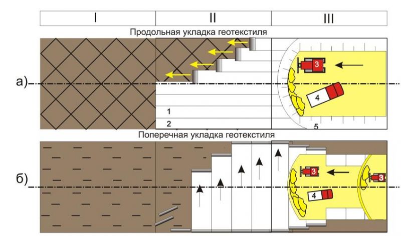
With a zero profile, loose soil is compacted in the trough to h \u003d 0.5-0.7 m. Such soils are characterized by a high plasticity number and easily turn into a soft plastic state. Therefore, the construction of embankments in humid areas with minor violations of the requirements leads to significant deformations. In 2, 3 climatic zones, the upper part of the embankment at h \u003d 1.2 - 1.0 m should be poured from sandy and sandy loamy soils. The lower part is made of rocky soils.
Prior to paving, the top of the subgrade (including in the recesses and zero marks) must be carefully profiled and compacted to a depth of:
h \u003d 2D \u003d 2 x 36 \u003d 72 cmwhere
D - the diameter of the circle, equal to the imprint of the wheel of the settlement car.
When laying canvases to create protective layers along the subgrade, rolls are rolled out manually by a link of three road workers. After rolling out the first meters, the edge part (in width) of the canvas is pressed to the ground with two or three anchors (rods with a diameter of 3-5 mm) with a length of 15-20 cm with a bent upper and pointed lower ends. With further rolling, the web is periodically flattened with a small longitudinal tension and fastened to the ground with anchors (or in another way) after 10 - 15 m (after 1.5 - 2.0 m when the geotextile layer is installed on a weak base). The fastening is carried out in order to avoid displacement of the web under the influence of wind load, laying of the overlying layer, as well as to maintain a small preliminary tension of the geotextile. Cloths are laid with an overlap of at least 0.3 m and, if necessary, are additionally connected. When arranging a layer of geotextiles at the base of the embankment, composed of soft soils, the overlap is increased by a distance of at least 0.5 m.
|
|
|
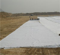
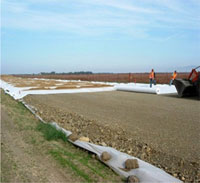
When laying canvases to create protective reinforcing layers (in the transverse direction - Fig. 1.b), the overlap in the absence of connection should be at least 0.5 m. The canvases are fixed to the ground with anchors installed on the overlap width in 1.5 - 2 , 0 m. The connection of paintings allows to reduce the amount of overlap. A preferred type of joining of the webs is their stitching using bag sewing machines.
The principles of the development of the project of work (PPR)
Goals and objectives: development of methods for the production of work, the nomenclature of road machines and their number, flow direction, priority of work, achieving economic efficiency. The main document is a calendar schedule.
The calculation of complex mechanized flow is performed by the method of variant design. Economic and mathematical methods using computers made it possible to move from the variant method to the optimal calculations of the complex flow. For example, a feasibility study shows that it is better to erect an embankment from the imported soil, and transport the cohesive soil to the dump. When developing PPR, they are guided by the year-round construction of the subgrade, attributing to the winter period those works that are more profitable to perform at this time.
Selection of earthmoving machinery and earthworks
The choice of machines and mechanisms is carried out taking into account the natural conditions, the volume of excavation, timing, working marks of the subgrade. Within the boundaries of technical possible applications, the appropriateness of their use is determined. Due to the complexity of the task, modern mathematical methods and computers are used. Earthworks are among the most mechanized. The level of mechanization reaches 97%. With a quiet relief and small amounts of earthwork, earthwork is called linear. The front of their implementation is gradually moving behind the preparatory work. Concentrated earthwork is performed by specialized squads of machines. They must be completed before the linear flow approaches. During the construction of city streets and roads, the following types of earthworks are encountered:
- the construction of embankments from imported soil;
- the construction of embankments from the recesses;
- development of excavations with soil removal to the dump;
- erection of embankments from lateral reserves;
- the device of half-mounds - half-notches on the slopes.
The machine link consists of the main and auxiliary machines: the main ones include excavators, scrapers, bulldozers, grader elevators; to auxiliary - machines for loosening, leveling, compaction, watering. The choice of machines depends on the volume of earthwork, the range of the wagon, the type of soil and other factors. When building the embankment from the reserves and excavations with a carting distance of up to 50 m, bulldozers are used; with a carting distance of up to 600 m - trailed scrapers with a bucket capacity of up to 6 m 3; with a carriage range of up to 3000 m - self-propelled scrapers with a bucket capacity of 9-10 m 3; at large distances - excavators and dump trucks; with the volume of earthwork over 200-500 thousand m 3, the hydromechanization method (hydromonitors) is used.
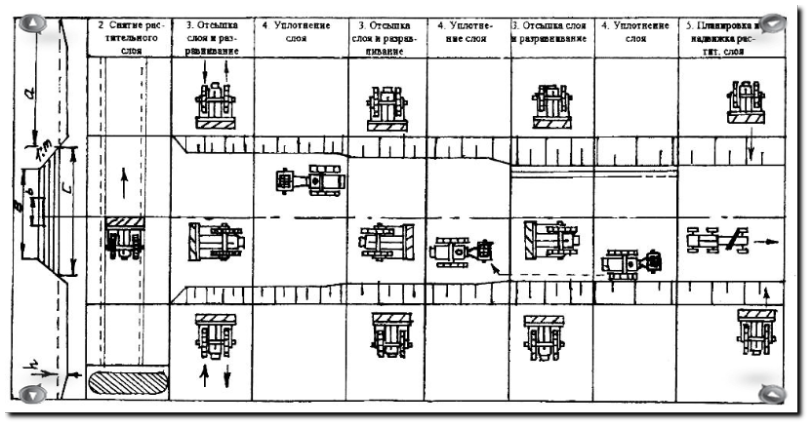
The scheme of development, movement and laying of the soil during the construction of the embankment with a bulldozer
Bulldozer It is a caterpillar tractor or tractor on pneumatic tires, equipped with a wide blade, which is mounted perpendicular to the longitudinal axis of the tractor or at an angle that allows you to move the soil to the side. In a number of designs of bulldozers, the blade can be rotated in the transverse and vertical plane, tilted. Depending on the work performed, the road cultivators, brush cutters, uproots can be mounted on the frame instead of the blade, which increases the use of the base tractor. In the process, the bulldozer digs, moves and distributes the soil.
To separate the soil from the array, the blade blade is deepened while the bulldozer is moved forward. Soil accumulates in front of the blade, forming a prism of drawing. Cutting continues until this prism reaches the top edge of the blade. Then the bulldozer moves the prism of the drawing to the place and the soil unloads in a heap, lifting the blade to failure or leveling with a layer of the required thickness. The thickness of the layer depends on the type and weight of the machines for compaction.
The greatest resistance occurs when the bulldozer is in the process of digging the soil. When moving soil there are power reserves. When cutting (digging), they achieve the maximum amount of soil to be cut out at the dump, the full use of engine power and the minimum time required to set the drawing prism. Three basic schemes of soil digging are used: rectangular chips (with constant thickness), wedge (with variable chip thickness) and comb.
When digging with rectangular shavings, the bulldozer blade is first buried as much as possible into the ground, taking into account the capacity of the bulldozer in terms of power and soil group. Then, without changing the position of the blade, the bulldozer moves forward, cutting off even chips along the entire path of soil collection. The scheme is effective when working downhill and developing a notch in inclined layers. The tractor power is fully utilized, the chips are cut out thick and uniform, the path and time of drawing the prism of the drawing are reduced. This scheme is used when removing the plant layer, while the chip thickness is not limited by the capabilities of the bulldozer, but by the technological conditions of work and the thickness of the plant layer.

The technology of work with a bulldozer: a - cutting (digging) of the soil; b - movement; c - unloading; 1 - rectangular shavings; 2-wedge shavings; 3 - comb chips; 4 - a pile of soil; 5 - soil layer; 6 - prism of drawing
The wedge killing scheme is used when working on light and slightly moist soils. The blade of the bulldozer at the beginning of the set is buried in the soil to the maximum possible value, then when the bulldozer moves forward, the blade is gradually raised, gaining soil on it. With this pattern of soil digging, the cutting path is reduced compared to rectangular cutting and the set time is reduced. When working on heavy dense soils, due to the difficulty of deepening the blade, this scheme is not practical.
A comb pattern is used in the development of heavy dense soils. The blade is first buried as much as possible into the ground. When the engine speed starts to decrease, the blade is raised to approximately 3D depth. Such deepening and rises are repeated 2-3 times. During these operations, a complete set of soil on the dozer blade occurs. Using this scheme, almost 100% of the tractor power is used, the set time is reduced compared to the rectangular scheme, the path of forming the drawing prism is also reduced, but the driver quickly gets tired due to the large number of switching levers. The application of all schemes is rational on soils of optimal moisture.
Moving the soil with a bulldozer is economically profitable at a distance of 25-50 m. This is due to the fact that, when moving, part of the soil spills out beyond the dump. The longer the travel path, the greater the loss: (0.025-0.032) L for cohesive soils and (0.06-0.07) L for incoherent. Losses can be reduced by moving the soil in a trench way or in soil rollers formed at the beginning of the movement.
The work of the bulldozer in segments is effective when the soil is delivered to the dump site not immediately, but in stages. The whole essence of the working course of the bulldozer is divided into three parts. First, the soil is accumulated in the first section, then in the second, and after that it is moved to the third. The tractor power is fully utilized, since an increased amount of soil moves in the third section.
Loss of soil during movement is reduced if you use dumps with side flaps and visors. However, in dense soils, digging conditions deteriorate due to additional resistance on the openers. Hydraulically controlled articulated windshields can be used. During digging, they can be removed behind the blade, and during movement, set at an angle of 45-90 °. When working in soils of groups I and II, expanders, in addition to increasing production and the range of movement of the soil, can reduce specific fuel consumption by 10-20%.
To increase the efficiency of digging the soil with a bulldozer, dumps are used with an average knife protruding forward. This increases the output of the machine by 20-40%. Increases in production are achieved by shortening the path and duration of the set of drawing prisms. Protruding knife - removable or forcibly retractable. To compensate for soil losses, it is possible to move the soil to the blade with a small depth of the knife.
Increased adhesion of moist soils significantly reduces the production and quality of the machine. In order to reduce adhesion, the blade is coated with compositions (epoxy resin with the addition of fluoroplastic varnish FB-F-74D), the working body of the machine is heated with exhaust gases of the engine, vibration of the working body, electroosmosis are used. It is based on the fact that when a constant electric current is passed through the soil at the cathode (the working surface of the machine’s working body), water is released, which serves as a lubricant for soil friction and reduces adhesion due to the partial screening of the molecular field of the solid phases of the soil – work surface system when interaction.
Turning the bulldozer to idle - returning to the place of cutting in forward motion is advisable only at distances of soil transportation greater than 50 m or when bulldozers do not have high reverse gears. In reverse shuttle mode, as a rule, it is recommended to perform on the track of the working stroke in higher gears of the tractor.

Excavation of the soil with a bulldozer with movement into the embankment with longitudinal passages I, II, III, IV - tiers:
1 - trenches used to move soil into the embankment; 2 - walls of trenches; 3 - shelves of slopes; 4-8 - the procedure for laying soil layers in the embankment
The construction of the subgrade with a bulldozer during the development of soil in the excavation and its transportation to the embankment. Deep excavations are usually developed in tiers. Development begins with the areas closest to the embankment being constructed. The number of tiers and trenches along which soil is transported is determined by the size and shape of the excavation, as well as the size of the blade used bulldozer. Soil in the lower tiers of the recesses can be overwetted with groundwater, which, without proper drainage, will accumulate in low places. To avoid this, it is necessary in the process of working to withstand the slopes of the bottom of the bottom of the developed excavation within 0.01-0.03. The development of the excavation is carried out in such a way that the bulldozer with the filled blade is moved along the planned path. It is advisable to plan the path at idle of the bulldozer. To increase production use the work of the bulldozer segments.
If the height of the embankment exceeds 1.5 m, then part of the subgrade, located above this mark, is scattered with scrapers ”, soil is delivered by earth-moving vehicles and dump trucks. For the smooth movement of vehicles and Loaded: scrapers on the slopes of embankments arrange gentle exits with bulldozers. After completion of work on the embankment, the soil of the ramps is used to dust roadsides or slopes.
If the embankments are low, the construction of the subgrade from the side reserves is classified as linear work. Since bulldozers overcome large rises (up to 20-25 °) and are heavily loaded when moving soil from the reserve to the embankment, it is advisable to use several bulldozers - some for moving, others for leveling the soil in the embankment. The following is the technology for the construction of the subgrade with bulldozers complete with leveling, sealing and planning machines (grader). The construction of the embankment is carried out by three links of bulldozers with rollers on pneumatic tires. The first link sprinkles and compacts the first layer of the embankment, the second - the second and third; - the last upper layer. Planning work is carried out by motor grader No. 1 complete with a bulldozer 9, which subsequently makes the restoration of the reserve. 
The construction of the embankment during the joint work of scrapers and bulldozers: bulldozer; 2 - cam roller; 3 - roller on pneumatic tires; 4 - soil development; 5 - scraper; 6 - unloading; 7 - grader
If it is not possible to fill the embankment to its full height with three links, then they can be transferred to fill and compact the next layers.
The technological scheme of the construction of the embankment with a bulldozer from the side reserves

Scheme of work of the bulldozer on the slope: passages of the bulldozer:
1 - transverse; 2 and 3 - longitudinal
During the construction of the embankment from the side reserves, the zonal-integrated scheme of work by a set of machines is effective.
The soil leveling in embankments is carried out with parallel bulldozer passages over the planned area so that the captured strip overlaps the previous one by 20-30 cm, and the dump is kept above the embankment surface at a distance equal to the specified thickness of the layer to be compacted. The movement of the bulldozer is organized so that it moves along the already planned strip, so that the layer is evenly distributed.
The erection of earthen yolotn on the slopes occurs in a terrace way with a gradual deepening and development of the shelf to the required transverse profile. In this work, bulldozers with a rotary blade are more convenient, the production of which is approximately “and 50-60% more than bulldozers with a rotary blade.
If this is done as a universal bulldozer, its movement is organized by longitudinal strokes along the terrace or embankment. The semi-rotary bulldozer makes transverse and oblique transverse passages. In the first and in the second case, the cut soil is dumped downhill.
Prior to the start of the construction of the subgrade in the half-half-half-embankment, the subgrade is marked with stakes that fix the axis and boundaries of the embankment, the boundaries of the development of the recess and the upland ditch. First, a mountain ditch is developed, ledges are cut or the base of the embankment is plowed. The bulldozer develops a slope with longitudinal passages with a blade installed at a capture angle of 67 °, starting from the top of the slope, gradually moving down to the side of the half-mound. After longitudinal passages, the formed soil shaft is moved into the embankment with a bulldozer with additional oblique passages. The earthen blade is carried out with a bulldozer to design elevations.
Bulldozers, scrapers, excavators with vehicles are effectively used for the longitudinal movement of soil from a recess into an embankment. The rational boundaries of their application do not remain constant, but vary depending on the soil group, terrain, methods of work and the construction area. The rational range of movement of the soil will be such that the cost of 1 m3 of land is less than or equal to the cost of developing a competing machine.
During the construction of the embankment, the thickness of each layer to be poured depends on the type of compacted means. Before compaction, the subgrade is planned with a bulldozer or motor grader. When using scrapers, there is a partial compaction of the bed with pneumatic tires. This method is not recommended for the development of heavy, hard, waterlogged soils.
When developing soil with a scraper, the following schemes are used.
Mound - reserve:
- zigzag - for suburban roads with a section length of more than 200 m;
- figure eight - with a plot length of less than 200 m;
- elliptical scheme - with a section length of up to 100 m and one-way reserves;
- in a spiral - with bilateral reserves and the difference between the elevations of the embankment and the reserve is less than 3 m.

Schemes of movement of scrapers during the construction of embankments from soil reserves:and - on the "zigzag"; b - according to the "eight"; in - by ellipse; g - in a spiral
Departures and exits with a slope of ≤ 20% are envisaged.
When using imported soils for the construction of the embankment, excavators with a bucket capacity of up to 1 m 3 are used with interchangeable equipment - a direct shovel, the inverse is shown. Schematic diagram of the bulldozer operation on the slope: bulldozer passes: I, dragline. A straight shovel is used in dry faces when developing soil above the level of the machine and a sufficient height of the face.
Backhoe and dragline are used in the development of soil below the level of standing of the machine. Minimum face height: I - II soil group - 0.7 ... 1.15 m; III group of soils - 1.8 ... 2.5 m. The best working conditions for the excavator: the height of the face is the highest cutting height of the soil.
The soil is delivered to the road by cars, it is poured in layers on the entire width from the edges to the middle, then a rough layout with bulldozers; partial compaction is ensured by the regulation of the movement of vehicles delivering soil. In urban conditions, organize the joint work of all machines and mechanisms.
Subgrade compaction
The soil compaction of the subgrade is carried out in layers at the optimum humidity in several passes along one track. Soils are three-phase systems: soil skeleton, water and air. Porosity and humidity have a decisive effect on its condition: with increasing density, porosity decreases, and strength increases; deformability, water permeability, swelling and frost heaving are reduced, which increases the strength and stability of the subgrade.
The purpose of compaction is to achieve the required density, strength and stability (elastic modulus, coefficient of friction and adhesion), minimum frost heaving. The seal ensures evenness and density of the pavement. Proper compaction allows to reduce the thickness of the pavement, to ensure its work within the elastic stage, regardless of the season. The cost of compaction is about 0.5% of the total cost of construction and the cost of compaction is fully paid off by increasing the durability of the pavement.
The main characteristic of compaction is the average density (δ), which can be determined by the formula:
ρ is the density of mineral particles of the skeleton of the soil;
W - humidity,%;
ν is the volume of air that remains in the pores after compaction;
δ, W, ν - depend on the genesis of the soil, its degree of dispersion, load, etc.
The finer the soil, the greater the influence of moisture. At low humidity, water envelops the soil particles, forms films that are in the zone of action of intermolecular attractive forces. When compaction occurs, the mutual movement of soil particles and their denser packing. An increase in humidity leads to an increase in film thickness, a decrease in density and viscosity. Reducing the frictional force during compaction improves compaction, but lowers the modulus of elasticity and shear resistance. When the humidity reaches the yield point, free moisture appears, the soil goes into a fluid state.
Humidity (W opt), corresponding to the highest soil density (δ naib), achieved with the least expenditure of energy for compaction, is called optimal (Fig. 3.12).
The compaction of the subgrade is characterized by a compaction coefficient:
δ Tr - the required density;
δ naib is the highest density.
K opl should be 0.95 ... 0.98. me (p. 120)
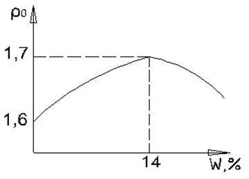
Graph of soil density versus moisture
When compacting the subgrade, the following methods are used:
Rolling. Rollers are used on pneumatic tires with a ballast of 25 tons. Cam rollers weighing up to 10 tons are used for both cohesive and non-cohesive soils, and on pneumatic tires they are recommended for sandy and loamy soils.
Tumbling with a falling plate using an excavator or crane.
Vibration using vibratory rollers, recommended for disconnected soils.
List of references
Car roads. SNiP 2.05.02-85
Gesenzwei. L.B., Gurevich L.V. City streets and roads. - M., Stroyizdat, 1968
Road construction. / reference book edited by V.A. Bochina. - M .: Transport, 1980.
Slavutsky A.K. Agricultural roads and sites. - M.: Higher School, 1980.
Babkov V.F. Car roads. - M .: Transport, 1989.
Building streets and urban is expensive. - M.: Stroyizdat, 1974.
Evgeniev I.E., B.B. Karimov. Roads in the environment. - M .: Transport science, 1997
Rohman V.A., Vizgalov V.M., Polyakov M.P. Crossing and adjoining highways. M .: - Higher school, 1997.
Materials and products for road construction: Reference / edited by M.V. Gorelysheva. - M .: Transport, 1986.


