Ground wall equipment. Technology "wall in the ground" for the installation of underground structures
Wall-in-ground technology for the device underground facilities
Underground structures, depending on hydrogeological conditions and the depth of the laying, are carried out in different ways, the main of which are open, "wall in the ground" and the method of the lowering well.
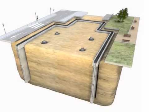
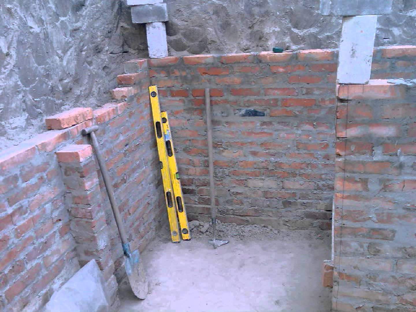
The essence of the “wall in soil” technology is that excavations and trenches of various configurations are arranged in the ground in plan, in which the enclosing structures of the underground structure are erected from a monolithic or precast concrete, then, under the protection of these structures, they develop an internal soil core, arrange the bottom and erect internal structures.
In domestic practice, several varieties of the "wall in soil" method are used:
Piling, when the building envelope is formed from a continuous row of vertical bored piles;
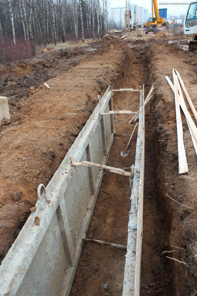
Solid wall trench made of cast concrete or prefabricated reinforced concrete elements.
The technology is promising for the construction of underground structures in urban areas near existing buildings, during the reconstruction of enterprises, in hydraulic engineering construction.
Using the technology "wall in the ground" you can build:
Impervious curtains;
Small tunnels for the subway;
Underground garages, crossings and junctions on highways;
Tanks for storing liquids and sedimentation tanks;
Foundations of residential and industrial buildings.
Depending on the properties of the soil and its moisture, two types of walling are used - dry and wet.
The dry method, in which clay mud is not required, is used in the construction of walls in low-moisture stable soils.
Pile walls can be built both dry and wet, while sequentially drilling wells and concrete piles in them.
The walls of underground structures are erected in a wet way in water-saturated unstable soils, which usually require fixing the walls of the trenches from collapsing the soil during its development and during the laying of the concrete mix. With this method, during the operation of earthmoving machines, the stability of the walls of the recesses and trenches is achieved by filling them with clay solutions (suspensions) with thixotropic properties. Thixotropy is an important technological property of a dispersed system to restore the original structure, destroyed by mechanical stress. For a clay solution, this is the ability to thicken at rest and to protect the walls of trenches from collapse, but also to liquefy from vibrational influences.
In the recesses, open to the required depth and width under the clay mortar, this mortar is gradually replaced, using monolithic concrete, prefabricated elements, various mixtures of clay with cement or other materials as supporting or enclosing structures.
The best thixotropic properties are bentonite clays. The essence of the clay solution is that hydrostatic pressure is created on the walls of the trench, preventing them from collapsing, in addition, an almost waterproof clay film 2 ... 5 mm thick is formed on the walls. The claying of the walls of the recesses makes it possible to abandon such auxiliary and labor-intensive work as sheet piling, water reduction and soil freezing.
When extracting trenches, cyclic and continuous equipment is used; usually the width of the trenches is 500 ... 1000 mm, but can reach up to 1500 ... 2000 mm.
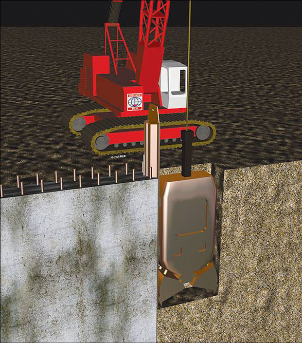
For the development of trenches under the protection of clay mud, general-purpose earthmoving machines are used - grabs, draglines and shovels, rotary and impact drilling rigs and special bucket, milling and plow installations.
Drilling equipment allows you to arrange a "wall in the ground" in any soil conditions with a depth of up to 100 m.
It is impractical to use the "wall in the ground" method in the following cases:
In soils with voids and caverns, on loose landfills;
In areas with former masonry, fragments of concrete and reinforced concrete elements, metal structures, etc .;
In the presence of pressurized groundwater or areas of large local soil filtration.
The simplest technology is the work with the installation of impervious curtains, which are usually made of monolithic concrete, heavy, scrap and hard clay. The purpose of the curtains is to protect the dams from the penetration of water beyond the dam body.
An airtight curtain can be used when trenching pits to protect them from flooding by groundwater. There is no need for freezing the soil or lowering the level of groundwater with needle-filter reducing devices. The curtain operates constantly, while other methods are used only for the period of work, although groundwater can be very aggressive.
The works on the fragment of trenches, as well as the production of subsequent works, in the case of close proximity of the foundations of existing buildings, are carried out by separate captures, usually through one, i.e. first, third, second, fifth, fourth, etc.
The length of the concreting grips is assigned from 3 to 6 m and is determined by the following criteria:
Conditions for ensuring the stability of the trench;
Accepted concreting intensity;
The type of trenching machine;
The design and purpose of the "wall in the ground."
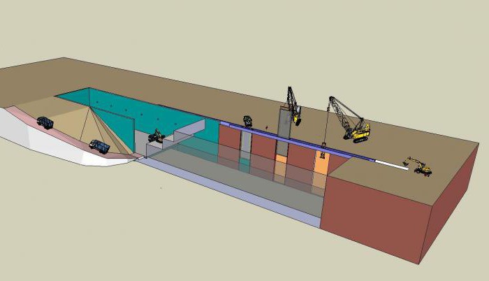
The sequence of work when installing monolithic structures according to the “wall in soil” method (Fig.):
1) drilling end wells on the gripper;
2) development of the trench in sections or sequentially over the entire length with constant filling of the open cavity with bentonite solution, with limiters dividing the trench into separate grips;
3) installation on a fully open grip of reinforcing cages and lowering to the bottom of the trench of concrete pipes;
4) laying the concrete mixture by the method of vertically moving pipes with the displacement of the clay solution in a spare tank or in the adjacent, developed section of the trench.
The wall-in-ground reinforcement is a spatial framework made of steel of a periodic profile, which should already be 10 ... 12 cm trenches. Before lowering the reinforcing cages into the trench, it is advisable to moisten the rods with water to reduce the thickness of the adhering clay film and increase the adhesion of the reinforcement to concrete .
Fig. 1.1. The technological scheme of the device "walls in the ground":
1 - foreshacht device (strengthening the top of the trench); 2 - digging a trench for the length of the grab;
3 - installation of limiters (jumpers between grips); 4 - installation of reinforcing cages;
5 - concreting on the gripper by the method of vertically moving pipe
Concreting is carried out by the method of vertically moving pipes with continuous laying of concrete mixture and uniform filling of the entire grab with it from the bottom up.
Concrete pipes - metal pipes with a diameter of 250 ... 300 mm, wall thickness of 8 ... 10 mm, neck - the volume of the pipe, a removable valve below the neck, wads of burlap.
Cap Size Limiters:
With a depth of trench up to 15 m, pipes with a diameter smaller than the width of the trench by 30 ... 50 mm are used; they are removed after 3 ... 5 hours after concreting on the grapple, and the resulting cavity is immediately filled with concrete mixture;
With a trench depth of 30 m, a limiter is installed in the form of a steel sheet, which is welded to the reinforcing cage. If necessary, the sheet is reinforced by welding channels.
With a grip length of more than 3 m, concreting is usually carried out through two concrete pipes at the same time. To increase the plasticity of concrete and its workability, plasticizing additives are used - alcohol stillage, superplasticizers.
Breaks in concreting - up to 1.5 hours in the summer and up to 30 minutes - in the winter.
The concrete mixture is laid to a level that exceeds the height of the structure by 10 ... 15 cm for the subsequent removal of the concrete layer contaminated with clay particles. When using vibration seals, vibrators are mounted on the lower end of the concrete pipe. For pipes up to 20 m long, one vibrator is used, and up to 50 m long, two vibrators are used.
Pipes at the boundary of the grips must be removed. Early extraction leads to destruction of the edges of the formed spherical shell, which is undesirable, and later leads to pinching of the pipe between concrete and the ground, and considerable efforts are required to extract it. Therefore, often, instead of pipes, they put non-removable lintels from sheet metal, channels or I-beams, which are necessarily welded to the reinforcing cages of the structure.
Sometimes, to protect the mouth of the trench from destruction and shedding, forshahts are arranged from prefabricated elements or metal - the heads of trenches up to 1 m deep to strengthen the upper layers of the soil, or this is a trench with upper parts of the walls strengthened to a depth of 1 m.
Disadvantages of the “wall in soil” technology: adhesion of reinforcement to concrete is deteriorating, since clay particles adhere to the surface of the reinforcement; many difficulties arise when conducting work in the winter, therefore, when conditions permit, they use prefabricated and precast monolithic options.
The use of precast concrete allows you to:
To increase the industrialization of work;
Apply rational form constructions: hollow, Tauri and I-beams;
Have quality assurance of the erected structure.
Disadvantages of precast concrete: special technological equipment is required for the manufacture of products, each time an individual section and length; the complexity of transporting products to a construction site; Powerful mounting cranes required the cost of precast concrete is much higher than monolithic.
The vertical gaps between the prefabricated elements are filled cement mortar with a dry method of production. With the wet method, the outer sinus of the trench is filled cement-sand mortarand the inside with a sand and gravel mixture. External filling will continue to serve as a waterproofing.
Two options of prefabricated-monolithic solutions are used:
the lower part of the structure to a certain level consists of monolithic concrete, overlying structures - from prefabricated elements;
prefabricated elements are used in the form of formwork-cladding, which is installed on the inner surface of the trench, the outer cavity is filled with monolithic concrete.
During the construction of tunnels and structures closed in plan after the installation of external walls, soil is removed from the inside of the structure and transported to the dump, the bottom is concreted or foundations are laid under the internal structures of the structure.
* We never have low-quality projects of pile foundations. We fully monitor and execute all design decisions. Our work fully complies with the requirements of the code of design and construction rules, as well as the rules of designing foundations.
The cost of work
|
Work | Dynamic driving of a single pile | Static indentation (immersion) of a single pile | Pile dynamic load tests (one test) | Pile static load tests (one test) | Relocation of construction equipment | Sheet piling fencing | Ground Wall Device |
|---|---|---|---|---|---|---|---|
|
unit |
running meters | running meters | 1 unit | 1 unit | 1 unit | ||
|
cost (rub.) including VAT * |
from 260 | from 600 | 10 000 | 65 000 | from 90 000 | negotiable | negotiable |
The main purpose of the construction "wall in the ground"
A wall in the ground is one of the high-performance technologies for creating enclosing structures made of concrete, reinforced concrete or precast concrete for a construction pit in conditions of high water cut of soils at a construction site. Typically, a wall in the ground is used on construction sites located in cramped conditions:
Within the city limits in the immediate vicinity of ancient and historically valuable buildings;
In cases when it is impossible to hammer a sheet pile protective wall near buildings due to the impact of shock or vibration loads on these buildings;
When there is no place for a pile protective wall or even sheet pile;
When the distance to the building does not allow to arrange the protection of the pit from bored secant piles, etc.
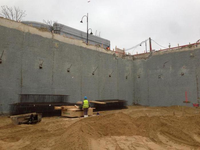
After the concrete has gained strength in the wall, soil removal from the inner zone can begin. If the wall in the ground, having passed the aquifers, is buried in the waterproof layer and will be waterproof itself, then work in the pit can be carried out without measures for external drainage, pumping water out, freezing water or reducing the water with other methods and means.
It can be used to create waterproof barriers, called damping curtains in the soil, not only made of concrete, but also made of thixotropic clay. In the latter case, the wall in the ground can be used as an obstacle for moving water flows in the horizontal direction. For example, when using such an obstacle, it is possible to prevent liquid production waste discharged into storages from spreading into the soils of the surrounding fields.
A properly designed and constructed wall in the ground can be used as the foundation of a building or structure, for example, an indoor pool. In this case, there is no need to tear the foundation pit, build a foundation in it, backfill the foundation pit from the outside and all these actions are under constant threat of flooding the foundation pit. Or build a protective sheet pile wall, tear the foundation pit under its protection, build a foundation, backfill the foundation pit, remove the protective wall.
Ground wall construction - video
How is the foundation of the wall in the ground?
A wall in the ground can be built on a variety of non-rocky soils. It is not allowed to build on quicksand, flowing, bulk or alluvial soils. Soils karst are not recommended, i.e. with large natural voids or karsts. It is very effective to use this method with a small depth of the waterproof layers.

To install the walls in the ground, at first they tear off a narrow vertical trench, the width of which can be from 0.4 to 1.5 and even 2 m. The maximum depth is determined by the capabilities of earthmoving equipment, and it allows you to dig up to 40 m and even deeper.
Trenches are protected from wall collapse by a clay solution based on bentonite clays. This solution has thixotropic properties: clay particles located at a short distance from each other interact with each other and form something like a spatial network of a loose structure. After a small external influence, the loose structure does not erode and does not collapse, only a slight movement of particles is possible. A small but constant load causes a constant movement of the medium.
With strong mechanical stress, the grid is destroyed and the formation of new grids begins.
These properties of such clay systems were called thixotropy. If the thixotropic solution is “do not disturb”, then it behaves like a thick jellied meat, and if mixed, it behaves like a thick liquid that turns into a jellied meat in a very short time.
This property allows excavation under a layer of bentonite clay mud, for example, with a clamshell mechanism. The selected soil is replaced with a solution that penetrates between the soil particles in a small amount and holds them together, and does not allow the walls of the trench to crumble with its pressure.
Reinforcing frames are lowered into a trench dug to a predetermined depth and filled with clay mortar, and concrete mortar is poured using concrete pipelines, starting the process from the bottom of the trench under a layer of clay mortar.
 Technology for the construction of reinforced concrete walls in the ground
The work is not carried out along the entire length of the future wall at once, but in small sections called grips. The length of each plot is from three to four to 10 meters. The distance between the two grips is also from three to 10 m.
The process of creating a wall in the ground can be divided into the following stages:
1. Digging from the grapple under a layer of clay mortar.
2. Lowering into the trench of restrictive elements that designate and protect the boundaries of the capture.
3. Installation in a trench, directly in a layer of clay mortar, sections of the reinforcing cage.
4. Concreting of the capture area through the concrete pipe, starting from the bottom of the trench with the gradual extension of the limiters.
After concreting three, four captures, you can start sampling the remaining sections of the soil. By this time, the concrete will gain its original strength, and will not crumble under the grab bucket.
5. Digging from pillars remaining between the grips. It is also carried out under a layer of clay solution.
Then repeat stages 2 - 5 on new sections of the future wall.
The construction of a wall in the ground is possible not only in the form of reinforced concrete wall, as described above, but also from prefabricated reinforced concrete slabs or blocks, in the form of a hardening clay-cement wall, or in the form of loose lump clay, from a clay-soil mixture. Moreover, all options for filling the trench after the completion of the wall construction should have a low coefficient of water filtration through the wall.
The spent bentonite clay solution is poured into separate containers, where it is separated from the soil, cleaned on vibrating screens, sludge separators, hydrocyclone sieve plants and fed to new sections of the trench.
Limiters in some cases do not extract, because they provide a bunch of separate sections. To do this, they are made in the form of reinforced concrete piles with a half-tee or double tee section or from steel pipes cut lengthwise or from metal profiles.
This type of "wall in the ground" can be made in the form of bored or even tapping rammed concrete or reinforced concrete piles.
Advantages of the technology “wall in soil”
Of all the advantages, we note only the most important:
A. The use of the thixotropic properties of bentonite clay solutions allows not to be used for fastening metal sheet pile walls, reinforced concrete or wooden sheet piles.
B. There is no need to organize a decrease in groundwater levels and / or water pumping.
B. significantly reduced volumes earthworks, the complexity and timing of construction.
G. It is possible to use high-speed methods of walling in the ground.
For this, use ready-made reinforced concrete panels weighing up to 20 - 30 tons. They are joined in the longitudinal direction, filling the joints with cast concrete. You can use smaller blocks, which are joined in height. The connection is carried out by the device locks.
Sometimes they arrange a prefabricated wall of reinforced concrete blocks and panels on a monolithic reinforced concrete base.

![]()

Patents for the construction of "walls in the ground" under the protection of bentonite suspension were first obtained by German scientists Brandt and Runnem in 1912. In 1936, Letzterr developed machines for the manufacture of "walls in the ground" in a continuous way.
In the early fifties of the 20th century, professors Feder and Graz invented the method of manufacturing a “wall in soil” without using casing pipes, and Professor Lorenz proposed a method of manufacturing a “wall in soil” that is currently used.
Currently, in large cities, the construction of high-rise buildings and the construction of buried structures are focused on the use of the "wall in soil" method instead of the traditional "open pit" or "lowering well" methods.
The “wall in the ground” method is intended for the construction of structures for various purposes buried in the ground. The essence of the “wall in soil” method is that the walls of buried structures are erected in narrow and deep trenches, the vertical sides of which are kept from collapsing with the help of a clay slurry that creates excessive hydrostatic pressure on the soil.
After the device in the soil, the trenches of the required size are filled, depending on the design and purpose of the structure, with monolithic reinforced concrete, prefabricated reinforced concrete elements or clay-soil materials. As a result, they form in the soil bearing walls structures or impervious diaphragms.
By designation, buried structures constructed using the “wall in soil” method are classified as follows:
- industrial - underground floors and foundations of industrial buildings, skip pits, continuous steel casting plants, wells for crushing workshops of mining and processing enterprises, bunker pits for car dumper; technological galleries, tunnels, etc .;
- housing and civil - underground floors and foundations of residential and public buildings laid to a depth of 30 m;
- transport - underground crossings and crossings under heavy traffic streets, small underground stations and tunnels; underground motorways; underground car garages and parking lots and other utility structures laid at a depth of 25-30 m;
- hydraulic engineering - water intakes and pumping stations located on the banks of rivers, reservoirs and lakes; impervious diaphragms, arranged both in the body and at the base of hydrotechnical retaining structures on rivers, in storage ponds for industrial wastewater that cannot be cleaned and pollute surface and underground waters; channels and drainage collectors; landslide and many other similar engineering structures.
The wall-in-ground method has several advantages over other construction methods:
- the ability to arrange deep pits in the immediate vicinity of existing buildings and structures, which is especially important during construction in cramped conditions, as well as during reconstruction of structures;
- sharply decreases, and in some cases there is no need for a device for dewatering or drainage; earthworks are reduced;
- there is no need for a backfill device and, therefore, uneven subsidence of floors and a blind area during their operation are eliminated;
- it becomes possible to simultaneously carry out work on the installation of aboveground and underground parts of buildings, which dramatically reduces the time of their construction;
- noiseless construction method. Measurements show that the noise level during the construction of the “wall in the ground” is lower than normal traffic noise.
Groundwater level reduction is excluded, as the “wall in the ground” concrete protects the structure from water penetration.
"Walls in the ground" are classified:
- as intended - bearing, enclosing and anti-filtering;
- according to the material - reinforced concrete, concrete, soil-cement, clay, combined;
- according to the manufacturing method - monolithic, prefabricated, precast monolithic.
The method of constructing walling and load-bearing structures using the "wall in soil" method can be used for any configuration and wall size in the plan. The depth of the “wall in pound” is limited by the requirements of the project and the capabilities of the available equipment.
The application of the "wall in the ground" method is advisable for the construction of underground structures in the cramped conditions of the existing buildings and reconstruction of existing enterprises.
The greatest effect is achieved in those cases when the "wall in the ground", cutting through the aquifers, is buried in the water-resistant layer. In this case, it becomes possible to perform work in the pit without a water reduction device.
Modern technologies make it possible to arrange structures of underground structures of various shapes, but structures of rectilinear walls are traditional and most frequently encountered.
The distance between the walls, as a rule, is taken up to 15-20 m based on the strength and stability of the spacer structures. With a distance of more than 20 m, the stability of the walls is ensured by the installation of anchor fasteners.
Anchor fastenings “walls in the ground” in one or several tiers should be arranged in the following cases:
- with a pit width of more than 20 m;
- with a pit width of more than 10 m, when, due to the peculiarities of the constructive solution, only temporary executions requiring redevelopment can be used.
Anchoring should be used in all soils, with the exception of loose sand, peat and clay flowing consistency.
Ensuring the stability of the walls through the use of inclined anchors is the most simple and effective way.
Walls have a thickness of 500; 600; 800; 1000 and 1200 mm and are constructed from monolithic reinforced concrete, in separate sections according to the project of works (PPR).
2. Machines and equipment for the construction of trench "walls in the ground"
The most expensive and complicated is the equipment for the formation of a narrow deep trench in the soils of groups I-IV to a depth of 50 m, a width of 0.5 to 1.2 m.
The following types of tunneling equipment are used to develop trenches:
- rotary equipment with submersible drive of rock cutting tool;
- rotary equipment with a rock cutting tool drive located on the surface;
- shock and rotational shock equipment;
- equipment with rock cutting tools of scraper type (dragline excavators, scraper trenchers, backhoe shovels, clamshell installations);
By the method of extracting the developed soil from the trench, all types of earthmoving machinery and equipment are divided into two groups:
1. Machinery and equipment, the digging tool of which is a grab, lifting to the surface of the developed soil with unloading into a vehicle or dump;
2. Machines and equipment developing the soil with a special drilling tool with its transfer to a working clay solution and with the removal of an air-lift installation to the surface.
In the first case, the developed soil does not clog the clay solution, but the number of operations associated with raising and lowering the grab increases, and in the second case, reverse circulation of the solution is necessary with its cleaning from sludge.
Below are the technologies of the device "walls in the ground", performed by some types of equipment.
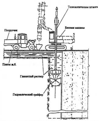
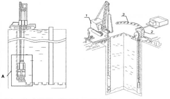
Development of soil in a trench with clamshell equipment for the device “walls in the ground”
At present, in Russia, high-performance imported clamshell equipment suspended on a telescopic rod of a hydraulic drilling rig of the type HR260 type from MAIT (Italy) or on a cable suspension of a special crawler crane like HS 855 HD from Libherr ( Germany), equipped with additional equipment for work on the technology "wall in the ground."
After the trench is developed to its full depth, the depth of the trench is checked, the trench is cleaned from the layer of crumbled soil and clay sediment by smoothly lowering and moving the grab along the entire plane of the trench.
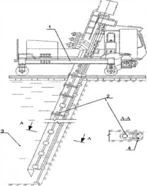
Ground excavation in a trench by continuous barrage machines for the “wall in the ground” device
Continuous barrage machines are used for the installation of anti-filter curtains by developing soil in straight sections of long length to a depth of 30 m.
Excavation of the soil in the trench by barrage machines is carried out under the protection of clay mud.
Destroyed soil is removed from the trench with an air-lift installation in the form of pulp.
The pulp goes to the treatment plant, or to the sump. Purified from the rock, the settled clay solution returns to the trench. As the barrage machine advances with the formation of a trench, the preparation of already developed sections for filling with antifiltration materials is underway.
For this, the site is isolated from the cavity of the rest of the trench using steel dividing inventory elements.
The range of geological conditions for machines of this type is limited by homogeneous, without large stony inclusions, sections represented by rocks with a compressive strength of up to 40 MPa. Continuous barrage machine model BM-0.5 / 50-2M BM-0.5 / 50-3ME produced by VIOGEM S.Ya. Beetle. According to JSC “SGSTU VIOGEM”, the productivity of a continuous barrage machine model BM-0.5 / 50-3ME for normal ground conditions is from 25 to 45 m3 of trench per hour.
Ground excavation in a trench by cyclic barrage machines for the “wall in the ground” device
Cyclical barrage machine designed by JSC “VIOGEM” named after S.Ya. Beetle model BM-30 / 0.5-3Sh - is used to develop both straight-line in plan and complex configuration trenches 0.5 m wide, including closed ones, up to 50 m deep and up to 150 m long.
The main operation of the technology of sinking by cyclic barrage machines is the sequential development of individual grips during successive immersion of the drilling tool and its removal. When developing partially overlapping grips with the formation of a continuous cavity of a trench up to 30 m deep, the problem of separating the sections to be filled is solved by installing inventory separating elements with their subsequent extraction.
When using rigid structural elements as a “wall in the ground” material, trench development can be carried out without the use of dividers. The range of geological conditions includes a wide range of rocks - from sandy loam and loam to fractured granites with a compressive strength of up to 100 MPa. The use of cyclic barrage machines is most appropriate for the construction of complex configuration trenches for various buried structures.
Excavation of the soil in the trench by milling machines for the device "walls in the ground"
Milling machines of the type SVD-500 and SVD-500P are designed for the formation of trenches in incoherent, half-rock and rock pounds. The SVD-500R machine is equipped with a special trolley of two platforms on a rail track, each of which is equipped with an electric winch with a lifting capacity of 8 tons.
The first platform contains equipment for driving a drilling tool, and on the second - for cleaning mud. The drilling tool is made in the form of an electric drill with a built-in electric drive.
A drilling tool suspended from the base machine slides along the runners of the guide template fixing its position.
The SVD-500 milling machine kit includes: a DK-9 compressor, a ChSGU-2 sieve-hydrocyclone installation, two MG2-4 clay mixers, a unit for the preparation and laying of GZ-1 clay soil paste, BS-2 clay mixer, airlift.
The milling machine provides the development of a trench up to 25 m deep. The machine operator controls the operation of the machine from the cab in which the control panel is installed. When driving, the machine moves to a predetermined interval automatically, while the amount of movement is set based on the control geological conditions of the soil.
3. Stages of the preparatory work for the construction of "walls in the ground"
Preparatory work
Before the construction of the "wall in the ground" the following preparatory work is carried out:
Construction site fencing;
- opening and transfer of underground utilities falling into the dimensions of the walls;
- layout of the surface of the site and the construction of temporary roads;
- Placement of temporary administrative buildings;
- preparation of places for the storage of building materials and structures;
- installation of technological equipment.
Replacing the soil to a depth of at least 3 m with imported sand and clay soil with compaction (Purchase ³ 0.95). Then, along the axis of the walls, a pioneer trench is developed with natural slopes of 1.5-2.0 m.
Construction of foreshacht (guide wall).
In the developed pioneer trench, a monolithic reinforced concrete foreship is being constructed.
Foreshacht is intended to provide:
- design direction for the development of the main trench;
- the necessary position of the grab in the ground;
- the possibility of suspension of reinforcing cages on it, installation of equipment for tunneling and concreting trenches;
- removal of overflowing clay mud.
Foreship constructions are determined according to the design and are constructed in separate sections from monolithic reinforced concrete.
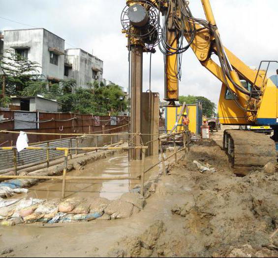
Installation and commissioning of a bentonite plant
Before developing a trench, it is necessary to install, test and commission a bentonite plant for preparing, supplying, cleaning and regenerating a clay solution, which should initially fill the space between the walls of the pioneer trench. Further, as the soil develops with a grab, a continuous supply of clay mortar must be made into the grab while maintaining its level not lower than 0.2-0.3 m from the top of the miners.
4. Stages of the main works in the construction of the "wall in the ground"
After the construction of the foresail, for the device “walls in the ground”, the following basic technological operations are sequentially performed:
- trench development;
- installation and removal of capturing limiters;
- installation of sections of reinforcing cages;
- Concreting of the trench by the method of vertically moving pipe (VPT).
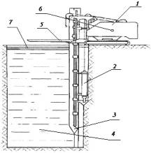
The construction scheme of the underground part of the structure using the “wall in soil” method according to the sequence of technological operations is shown in Fig. 3.1. 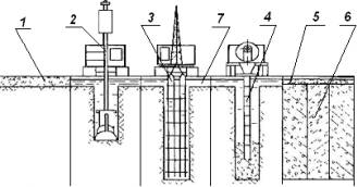
Fig. 3.1 Scheme of the construction of the underground part of the structure using the "wall in soil" method
1 - mince; 2 - development of the pound in trench grips; 3 - installation of armokarkas; 4 - concreting using the vertically moving pipe method (VPT); 5 - the device of the strapping belt around the perimeter; 6 - finished wall; 7 - clay solution
Trench Development
Trenches during the construction of underground structures using the “wall in the ground” method should be developed under the protection of a clay solution, with separate captures one after the other along the trench or alternately in different parts of the trench.
The method and technological sequence of the development of trenches is determined by PPR in accordance with the engineering and geological conditions of construction, the size and configuration and purpose of the wall being erected, and the characteristics of the trenching equipment.
In difficult ground conditions with a high level of groundwater, as well as at depths above 15 m, when inventory metal pipes are used as limiters, trenching should be performed in two stages through one or two grips.
The length of an individual grab is, as a rule, 2.0-6.0 m and is determined by PPR, based on the conditions for ensuring the stability of the walls of the trenches during their development and the size of the working body of the trencher.
The capture can be completed in one or more passes of the working body of the trencher to the full depth of the trench.
After developing the grab to the full depth, the depth of the trench is checked, the trench is cleaned from the layer of crumbled soil and clay sediment by smoothly lowering and moving the grab along the entire plane of the trench, test sampling of the sludge, monitoring the parameters and replacing the clay mud.
Installation of limiters of captures (stopsoles)
Steel spacer elements are installed along the edges of the grips as a butt element. To obtain high-quality joints, it is recommended to use a metal pipe with ribs from corners 75x75 mm. The corners are welded in such a way that, when the pipe is immersed, they cut into the sides of the trench by at least 30 mm.
The dividing elements are prefabricated and as they are lowered into the trench, they are assembled from the forward knife section 6 m long, the ordinary section 6 m and the required number of additional ordinary sections 1-2 m long (in accordance with the depth of the trench).
The lower knife part of the separation element must be buried in the bottom of the trench by at least 30 cm.
The dividing element and the upper end plate are mounted on the design of the foreshaft using special inventory devices, in excess of the level of the “collar” of the foreshaft.
After concreting the gripper, the stops are removed after 1-3 hours (before the start of adhesion to concrete).
Reinforcing frame installation
The reinforcing cage installed in the gripper must comply with the working drawings and have a passport. The type and design of the mounting joints of the reinforcing cage must correspond to the design.
The frame includes the necessary embedded parts made of sheet steel, mounting loops, retainers of the protective layer, providing centering of the frame in the trench, pipes for the passage of soil anchors.
The sections of reinforcing cages, immediately before their installation in the gripper, should be interconnected by electric arc welding of individual elements.
With a trench depth of more than 10-12 m, the frame can consist of separate sections joined at a height before lowering into the trench.
Apertures with guides for installing concrete pipes should be provided inside the frames.
Lowering the frame is carried out in a position that ensures its free passage into the trench with geodetic control of verticality and ensuring the design value of the protective layer between the supporting reinforcement and soil.
When installed in a gripper, reinforcing cages are installed on the upper part of the foreshaft “collar” using transverse pipes or profile beams so that the longitudinal bearing rods of the reinforcing cages do not reach the bottom of the trench by 25-30 cm.
Concreting
Concreting of walls is carried out under the protection of a clay solution, no later than 4 hours after lowering the reinforcing cages in the trench.
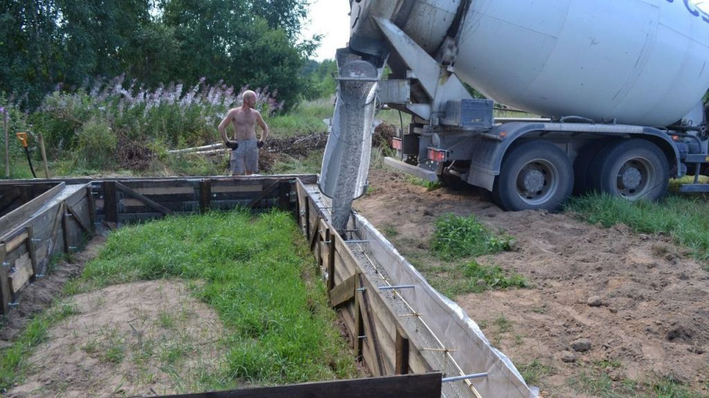
Transportation of concrete mixtures from concrete plants to the construction site should be carried out in concrete mixers.
Concreting should be carried out by the method of vertically moving pipe (VPT) with the simultaneous pumping of the displaced bentonite solution into the tank or the developed gripper.
Concreting of each next section should be carried out, avoiding interruptions in the supply of concrete.
When concreting under a clay solution, it is necessary to provide:
- isolation of the concrete mixture from the mortar during its supply to the trench;
- lack of mixing with the solution during installation;
- continuity of concreting within the grab;
- control of technology in the process of concreting.
Trenches should be concreted in sections using intersectional limiters.
Concreting by the VPT method is carried out using a collapsible or solid concrete pipe with an inner diameter of 250-350 mm. Installation of a precast concrete pipe includes the following operations:
- cleaning and preparation of links to work;
- installation of the support frame on the “collar” of the foreshacht;
- installation of the stand of the concrete pipe with the successive build-up of the links with the help of quick-detachable joints, when the previously mounted part is suspended on the support frame;
- installation and fixing on the pipe of the receiving hopper with a capacity of at least 1.2 volume of the concrete pipe.
The scheme of concreting the trench with the VPT method is presented in Fig. 3.2.
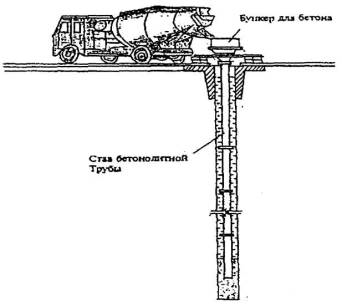
Fig. 3.2. The scheme of concreting trenches using the VPT method
A plug (for example, from sawdust or tow in a burlap cover) with a height of 20-25 cm, which is attached with a cable to the top of the receiving hopper, should be installed in the upper neck of the pipe.
The concrete mix from the concrete mixer is loaded into the receiving hopper in a volume 20% higher than the volume of the concrete pipe. After this, the pipe must be raised by 3-5 cm and cut the cable holding the cork. The cork under the influence of overpressure of the concrete mixture moves along the concrete pipe and pushes the clay solution inside it, preventing the delamination and mixing of concrete. To release the cork, the pipe filled with concrete mixture must be raised by 20-30 cm and then re-fill the hopper when lowering the level of concrete mixture to the mouth of the funnel.
To continue concreting, it is necessary to ensure a constant supply of the mixture to the hopper during the gradual lifting and upsetting of the concrete pipe.
In the current space deficit that is observed in large cities, developers are increasingly looking for ways to use it most rationally. To increase the usable area of \u200b\u200bbuildings under construction back in the twentieth century. architects turned their gaze up, creating giant skyscrapers.
But recently, an even more practical way of using precious land has been found: along with the growth in height, modern buildings grow inland. This allows you to place parking lots and supermarkets, warehouses and entertainment complexes in multi-level underground spaces. One of the technology that allows for underground construction is the “wall in the ground”.
 Groundwater may limit construction depth
This technology was developed for the construction of various underground buildings in urban conditions. However, it is quite suitable for private development.
Especially if the construction of a country house is carried out on expensive plots near megacities and the land owner wants to use his land to the maximum.
The depth of construction may be limited by subsoil waters, but often the “wall in the ground” passes through aquifers, dropping to 50 meters or more.
The essence of the method in a nutshell is the installation of the enclosing wall along the perimeter of the future underground premises. This wall should be deepened to the lowest point of the work or even lower.
Such technology can be conditionally divided into several varieties according to the method of constructing a protective wall.
- Trench or pile.
- Dry or wet.
Trench dry method
Provides for the use of prefabricated structures made of reinforced concrete or pouring cast concrete. Along the perimeter of the future building with the help of an excavator or a mill, a foreshacht trench is excavated with a depth of 2 to 3 m. 
 Foreshaft walls need to be strengthened
 Forshacht serves to designate the perimeter of a future building, as well as to strengthen the walls of a future trench. As you know, the upper part of the deep trench is the least stable.
To prevent shedding of the upper soft soil, the foreshaft walls are strengthened. After that, using crane or excavator grabs, the soil is sampled from the trench to the required depth up to several tens of meters.
After the trench is dug to the desired depth around the entire perimeter of future walls, monolithic reinforced concrete is poured into it or prefabricated concrete structures are mounted in it.
The “dry” method is quite simple and therefore most in demand in private construction, as well as on fairly strong soils with a low level of subsurface water.
Trench wet method
“Wet” technology is based on such a physical concept as “thixotropy,” which means the property of individual compounds and materials to independently restore their original shape. This unique property is most inherent in bentonite clays, the suspension of which can be diluted under the influence of vibration, and after transition to a calm state - again increase the density, returning to its original state. 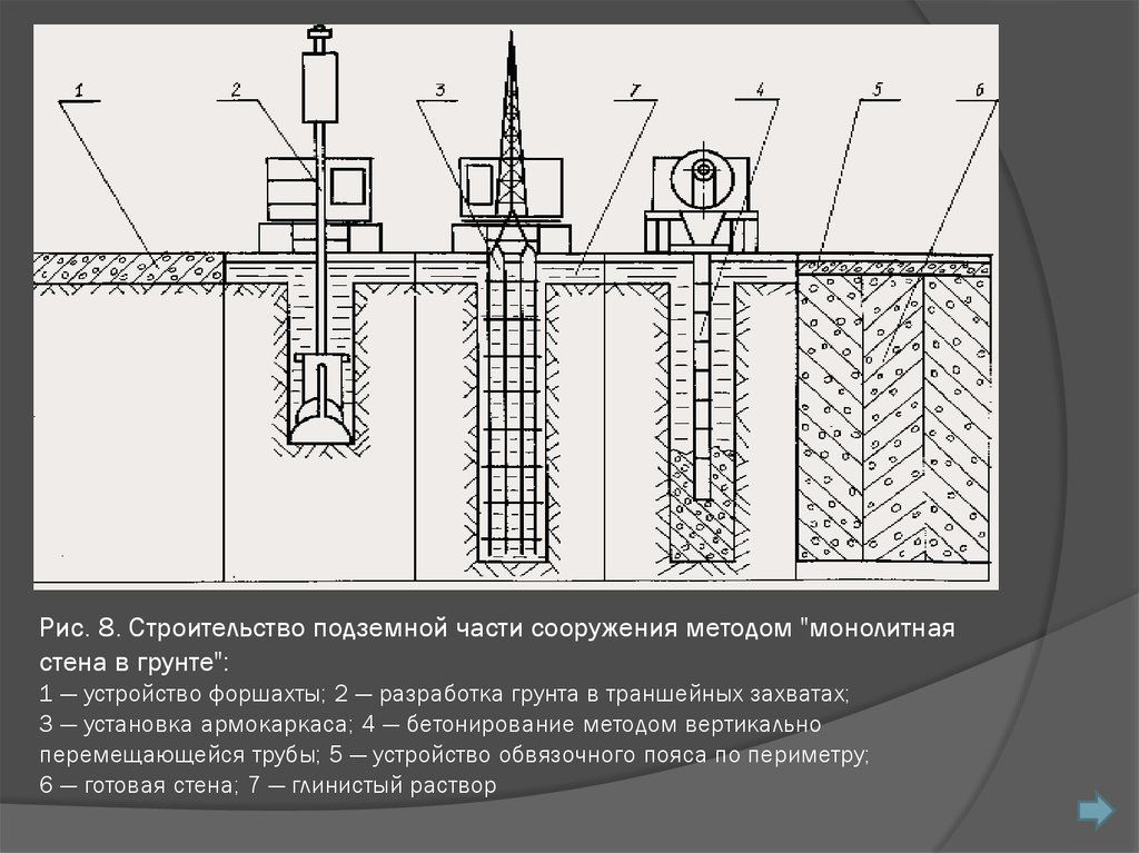
The initial stage of the “wet” trench method is no different from the “dry” one. A foreship device is also made to mark the contour of the deep trench. But further works follow a completely different scenario: the trench is filled with a suspension of clay in an aqueous solution - a clay suspension.
 The density of the suspension depends on the weakness of the soil.
 She, exerting pressure on the walls of the trench dug in weak soils, does not allow them to fall down, keeping their shape. In this case, the suspension itself is in a liquid state, without interfering with the excavation technique to deepen the trench.
To prepare the solution, clay and water are mixed in a ratio of 1 to 1 to 1 to 2. The density of the solution depends on the strength of the soil: the weaker the soil. The suspension should be all the more dense.
The “wet” method is usually used in large industrial construction, when work is carried out on soft soils, or when the “wall in the ground” must pass through groundwater. In private buildings, this method is not used because of the complexity of the technology and financial cost.
Pile method
 In the pile method, a wall of monolithic or precast concrete is replaced by a solid wall of bored piles, buried to the desired value. In this case, instead of digging a trench, a deep drilling method is used. After the device along the perimeter of the wells closely adjacent to each other, they are reinforced, and then filled with concrete mortar.
To create a dense barrier, impervious to underground moisture - the so-called "infiltration barrier", leader drilling technology is used. It implies the use of special pipes as piles, one of the sides of which has a concave groove running along the entire length of the pipe.
During installation, one pipe with its trough is tightly pressed against the convex part of another pipe. Thus, a strong and dense wall is obtained, through which groundwater cannot pass.
The pile method is mainly used in the construction of underground structures located in close proximity to other buildings. Including, if their depth is greater than the depth of the foundation of neighboring buildings.
Technology benefits
 You can mount a wall in the soil on any type of soil
 This technology of underground construction is the most common when erecting various structures at a depth of more than 5 - 7 m. Its popularity is due to a number of undoubted advantages:
- The ability to combine in one design the foundation of the building and the walls of its underground part.
- Simplicity and safety of work in comparison with other methods.
- The versatility of the technology - the installation of the wall in the soil is possible on almost any type of soil, including on water-saturated and weak substrates.
- When using this technology on soils with a high level of subsurface water, there is no need to divert or freeze them.
The only limitations for using this method may be the presence of large voids in the soil and a large layer of bulk soil.
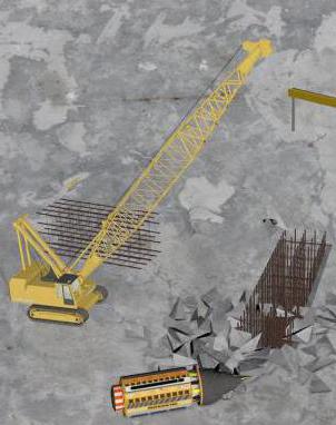
Used technique
The quantity and nomenclature of the equipment involved depends entirely on the volume of work and the technology for their implementation. If the “wall in the ground” for a low-rise country house can be constructed using a light wheeled excavator, then the construction of an underground structure during the construction of a skyscraper will require the involvement of a large number of specialized equipment.
A milling cutter or a light excavator can be used to set up the foreshacht. The injection of clay slurry requires a specialized mortar unit for its preparation and a concrete pump station for supplying a liquid solution to the trench.
Deep trenches dig with the help of linear (flat) grabs mounted on a crane or excavator. Wells for bored piles are created by rotary or impact-rotary drilling rigs.
Reinforcement of trenches and wells
When reinforcing trenches or boreholes, volumetric reinforced cages of corrugated reinforcement are used. During their manufacture and installation, a number of construction standards should be observed:
- Finished frames should be equal in length to the depth of the trench or well.
- For the formation of a protective concrete layer around the reinforcement, the width of the frame should be 120 - 150 mm narrower than the width of the trench or well.
- When constructing the frame, the wall structure, the expected load, which the "wall in the ground" will have to withstand, should be taken into account.
- In the design of the frames, gaps should be provided for the introduction of pipes for pouring concrete into them.
Before installing armokarkas in a trench filled with clay suspension ("wet" method), the reinforcement should be moistened with water. This allows you to reduce the sticking of clay suspension on it, as a result of which its adhesion to the concrete solution increases.
Pouring concrete
In industrial construction, concrete is poured using concrete pipes, which are moved using a construction crane.
They are pipes with a diameter of 20 to 30 cm with a wall thickness of about 1 cm, mounted from sections 1-2 m long, and are connected to a receiving hopper for concrete or a concrete pump station.
Concrete should be poured in compliance with the following specifications:

In private construction during the construction of the "wall in the ground" you can use concrete, made by yourself.

Precast concrete installation
Instead of pouring monolithic reinforced concrete into a “wall in the ground”, you can mount using ready-made concrete structures. This will significantly reduce the cost of effort and time, since in this case it will be possible to do with a narrower trench. Read more about building a wall in the ground in this video:
It will not be necessary to build a reinforced frame and make laborious pouring concrete mortar. Also, you will not need to wait until the monolithic casting has gained sufficient strength. Immediately after installing the underground wall from the finished structures and fixing them together, you can begin to excavate the ground for the device.
In modern megacities, there is an increasing trend towards a more rational use of space and densification of buildings. These circumstances dictate certain conditions to construction companies. On the surface, less and less free sites remain, which forces developers to resort to the construction of underground structures. Among other things, there are some objects that are more rational to build underground. This includes large warehouses, shopping and entertainment complexes, as well as garages. But underground construction is a rather time-consuming process, which requires the presence of certain experience and appropriate equipment from construction companies.
The solution to the problem described above can also be complicated by the fact that the soil is very heterogeneous, it can contain voids of different sizes, underground water currents. Sometimes, when examining the territory for development, it turns out that the rocks are quite weak. It happens that underground are all kinds of tunnels of engineering systems that are not mapped. At the same time, it is often necessary to work in cramped conditions, since the foundations of neighboring buildings are located quite close to the construction site, and the walls of high-rise buildings do not allow the cranes to fully deploy.
Solving the issue of the construction of underground structures
Depending on what the hydrogeological characteristics of the area are and how deep the premises will be, underground construction can be done in one of several ways. The most common are the "wall in the ground", the method of the lowering well, as well as the open method. The first technology in modern realities is quite common and still continues to rapidly gain popularity, because it can be used to solve the problem in cramped conditions without bothering the foundations of buildings located nearby.
Technology principle
The wall in the ground is built on a fairly simple principle, which provides for the preparation of the trench and excavation. Further, in the formed voids, reinforced concrete is usually used for this purpose. Under the protection of the obtained systems, internal structures, for example the floor and other elements, are equipped.
Varieties of method

The technology "wall in the ground" can be divided into several subspecies, such as: trench and pile. The first is the use of monolithic concrete and reinforced concrete sections, with the help of which a single wall is formed. The pile method involves the installation of bored supports, which are located in a continuous row. They allow you to form a strong enclosing structure. Whatever technology is used, it is more promising in comparison with alternative methods of erecting underground structures. It is advisable to use it when reconstructing existing buildings for any purpose.
Application area
A wall in the ground can be used when there is a need to erect anti-filter curtains, underground tunnels, garages, warehouses, tanks, various sedimentation tanks, road interchanges, as well as the foundations of buildings for various purposes.
Wet and dry methods
Given the strength of the soil and its moisture level, builders can choose the wet or dry construction method. The latter is not so expensive, because for him there is no need to prepare a clay solution. However, it can only be resorted to if there is confidence in the strength of the soil and the absence of underground currents. Wet technology is an ideal solution for the construction of large facilities in water-saturated unstable soils. If the construction is accompanied by the described conditions, then sometimes there is a need for additional strengthening of the walls of the trench. Ultimately, durable and reliable rooms are obtained.
Thixotropy
When a wall is installed in the ground, the technology may include the use of a wet method, in which such a thing as thixotropy is important. This property is inherent in a clay solution, which has the ability to restore its original form without mechanical stress. Due to this, a correctly selected suspension will gain strength at the construction stage and will liquefy from vibrational influences. This allows you to insure the walls of the trench from deformation. The highest thixotropic qualities are inherent
If we consider the additional characteristics of such solutions, then it is worth paying attention to their water-repellent quality. After hardening of the suspension on the surface of the walls will be affected which contributes to the formation of a waterproof film. Its thickness can vary from 1.5 to 5 millimeters, this is enough to protect the structure from water. The claying of the walls allows you to save on the reduction of the tongue of the tongue. This is one of the many advantages of the described technology.
Applied Equipment
 When creating a wall in the ground, the technology involves the use of appropriate equipment. It allows you to dig a trench. For this, a continuous device is most often used. A similar result can demonstrate a cyclic approach. For the formation of trenches, earthmoving machines are usually used, namely: bucket, plow, milling rigs, draglines, rotary and impact drilling rigs, grabs, and also backhoe shovels. The listed equipment will be quite enough to get a wall in the ground, which can be deepened by 100 meters. The conditions may be completely different. The “wall in soil” method most often assumes that the width of the trench will be equal to the limit of 1 to 1.5 meters. In some cases, projects are drawn up in which the width reaches 2 meters.
Cases of inappropriate methods
Undoubtedly, the described technology has many advantages, however, we can distinguish situations where the use of the method is impractical. The construction of the “wall in the ground” is not carried out if there are strong underground currents in the soil, with loose soil, and also when the site is dilapidated in the area. The technology should not be used when there are metal islands, as well as large fragments of concrete. When there are voids and cavities in the soil, work on the described technology should not be started either.
Impervious curtains
Manipulations to create impervious curtains can be considered as simple as possible. They are performed using heavy and hard clays, as well as monolithic concrete. The purpose of the curtains is to protect the object from water. Most often, such elements are used in the equipment of dams and digging pits. In the latter case, curtains are necessary to prevent water from entering the cavity. The workers will not be faced with the task of lowering the level, which is a rather time-consuming procedure. If we compare the curtain with step-down installations, the latter act temporarily while work is ongoing. Structures with curtains will not be afraid of the most powerful groundwater flows.
Capture Options
Before the foundation "wall in the ground" will be built, you need to calculate the length of the grab. Some factors will influence this parameter, among them:
- trench stability;
- design features and functionality of the structure;
- the type of equipment used to develop the trench;
- calculated concreting intensity.
Technology of work
The construction of a wall in the ground begins with the drilling of a well, after which trenches are prepared, which are simultaneously filled with a solution. The next step will be the installation of reinforcing cages, as well as concrete pipes. The final manipulations include the displacement of the clay mortar by supplying concrete mixture through a vertically moving pipe. Trenches can be developed full-length or in separate sections. based on corrugated steel rods. The resulting system should be 12 centimeters smaller than the width of the trench. Elements are wetted in water before installation, as this reduces the amount of adhering clay and increases adhesion to concrete.
Concreting
The construction of the wall in the ground involves concreting, which is carried out by the method of a movable pipe. The latter has a diameter in the range from 270 to 300 millimeters, while the wall thickness is 10 millimeters. Given the volume of the pipe, the neck is selected, and wads can be made of burlap.
Gripper limiters
The construction of the wall in the ground may involve trench deepening of 15 meters or less. In this case, pipes with a diameter of 50 millimeters less than the width of the trench should be used. 5 hours after concreting, the elements must be removed, and the resulting cavities are poured with a mixture. If the depth of the trench is greater than the mentioned parameter, then there will be a need to install a limiter. Its task is performed by a metal sheet, which is fixed to the reinforcing cage. The canvas can be strengthened by welding beams to it.
Increase in productivity
When the “wall in the ground” method is used in the construction process of a rather large object, and the grab length is more than 3 meters, it may be necessary to supply concrete mix of huge volumes. In this case, it enters through pipes, and for faster and easier laying, the plasticity of the solution is increased by plasticizers. The composition is poured in such a way that its surface overlaps the entire structure by 10 centimeters. This is required in order to be able to subsequently remove the contaminated concrete layer, because it will have a large amount of clay. Sealing will need to be done with the help of special equipment that is mounted on a concrete pipe. If its length is more than 20 meters, then it is recommended to use two vibrators.
Those pipes that will be located on the border of the grips are always removed. It is important to determine the extraction time correctly. If this is done too early, the edges of the shell may be damaged. If the extraction is too late, the pipe may get stuck between the concrete and the ground. In order to exclude such processes, sheet metal is often used instead of a pipe, with which you can create permanent, non-removable lintels. They must be welded to the reinforcing cages. To protect the mouth of the trench from deformation and shedding, it is necessary to equip the foresail, which is the head of the trench.
About soil pressure
If you need to find out what soil pressure is on the wall at a depth of z, then you can use the following formula: PR \u003d PS + PQ, where PS is the intensity of lateral pressure at a specified depth from its soil weight, taking into account bedding, water, and effective clutch; PQ is the lateral pressure intensity at said depth from surface loads. If, according to the design, the foresail is located on a specially formed dump above the surface of the earth, then the value is taken with a minus sign.


