Technical recommendations for the construction of sidewalks made of concrete slabs
THE GOVERNMENT OF MOSCOW
COMPLEX OF ARCHITECTURE, CONSTRUCTION,
DEVELOPMENT AND RECONSTRUCTION OF THE CITY
State Unitary Enterprise "NIIMosstroy"
TR 158-04
Moscow - 2005
Technical recommendations developed on the basis of the results of research and development work performed by the road construction laboratory of the State Unitary Enterprise NIIMosstroy, development and production works of SBM Zapchast-Service CJSC, SDM Gidroprivod CJSC, and also based on the analysis of domestic and foreign experience construction.
In the work on the document took part: Ph.D. L.V. Gorodetsky, Ph.D. R.I. Bega, V.F. Demin (State Unitary Enterprise “NIIMosstroy”), S.M. Arakelyants, Ph.D. I.I. Davitnidze (SBM Zapchast-Service CJSC), V.N. Arakelyants (ZAO SDM Gidroprivod).
GENERAL PROVISIONS
1.1. These recommendations apply to summer and winter periodin Moscow, ecologically clean sidewalks, pedestrian and garden paths, pedestrian streets, parking lots, entrances to residential and public buildings, pavements in the areas of social and cultural life (hospitals, clinics, schools, kindergartens, nurseries), at gas stations and playgrounds for various purposes from prefabricated coatings.
For the device of prefabricated coatings, slabs and small-sized figured paving elements are used, made of heavy and sandy concrete, as well as concrete using products of processing various industrial wastes, reinforced with metal and basalt fibers.
Paving slabs are products with a ratio of their lengthl to thickness h more than 4, with lower valuesl/ h£ 4 - small sized elements.
1.2. The winter period is considered the time of year between the date of occurrence of zero daily average steady temperature in the fall and the date of the same temperature in the spring.
1.3. To solve aesthetic, architectural and functional problems in modern urban construction, concrete slabs and small-sized paving elements can have various shapes and sizes, which are not always multiple of the width of the pedestrian lane (0.75 cm), adopted in GOST 17608-91 *.
1.4. To expand the product range of NIIMosstroy, lattice plate designs have been developed. The holes of the plates can be filled with small-sized elements, which can be used independently (applications,,). The holes in the slatted slabs can be filled with stone materials (gravel, gravel, crushed stone sowing, sand, etc.), as well as soil with lawn grass seeds.
1.5. Plates and paving elements for prefabricated coatings (including those with a decorative and colored surface) can be manufactured using various technologies, providing physical and mechanical properties that meet the requirements of GOST 17608-91 *.
1.6. The thickness of paving slabs and small-sized elements is selected in accordance with the project. The approximate thickness of prefabricated products for various structures can be adopted as follows: in areas where only pedestrian traffic is expected - 4 - 6 cm; if the movement of cars is allowed -³ 6 - 8 cm; if it is possible to check in trucks -³ 8 - 10 cm.
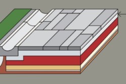
1.7. Structural elements of sidewalks include: a sandy underlying layer, a base of sand, a sand-cement mixture, crushed stone and low-cement concrete; concrete coating, incl. modified products. The technological sequence of work on the construction of prefabricated coatings includes the following steps: digging and compaction of the earthen trough; the device of the underlying layer; installation of side stone; foundation and coating of slabs or small-sized paving elements, followed by filling the seams. Depending on the hydrological features of the territory and the requirements of the project in the structural layers of sidewalks, sites, etc., the use of film and geotextile materials is possible.
1.8. The main options for prefabricated structures concrete products are presented in fig. .
Fig. 1. Structures of paving slabs and small-sized elements
1 - plates; 2 - loose sand or sand-cement mixture; 3 - the base of the sand-cement mixture, concrete B7.5, sand, gravel, bitumen-mineral mixture; 4 - sand frost protection layer; 5 - small-sized elements of paving; 6, 7 - a polyethylene film or geotextile such as dornite; 8 - basalt grid.
2. PREPARATION OF THE EARTH CANVAS AND DEVELOPMENT OF DRAINAGE DRAINAGE
2.1. The construction of the subgrade should be carried out in accordance with the requirements of SNiP 3.06.03-85 “ Car roads”And in accordance with the technical design of the work after completion of vertical planning, laying new and replacing old underground utilities, backfilling trenches and excavations with layer-by-layer compaction.
2.2. For production earthworks excavators with a bucket with a capacity of 0.25 m 3 to 1.0 m 3, bulldozers with a capacity of 80 - 250 hp, small and medium-weight motor graders should be used. For compaction use rollers on pneumatic tires of the type DU-30, DU-31, vibration rollers of the type DU-10, DU-10A, DU-14, static-action rollers with smooth rollers of the type DU-1, DU-11A, etc. The type of roller is selected depending on soil group subgrade and the width of the sidewalk, pedestrian street, walkway, etc.
2.3. The width of the trough of the subgrade, taking into account the installation of bead stones, should be 0.5 m more than the width of the coatings.
2.4. The construction of the subgrade should be carried out in layers. The filling, leveling and compaction of each layer is carried out in compliance with longitudinal and transverse slopes.
The thickness of the dumping layer should be assigned taking into account the safety factor for soil compaction, depending on its type, with humidity close to optimal (table).
2.5. Compaction of subgrade soil, including backfilling of trenches and pits, must be carried out at the optimum humidity to the required density, which corresponds to a compaction factor of at least 0.98 when measured after 25 m at points along the cross section. Sealing technique is selectable depending on thetype of soil and the thickness of the sprinkled layer (table.).
Table 1
The dependence of the safety factor on compaction on the type of soil at optimal humidity
|
Optimum humidity,% |
Seal safety factor |
|
|
Sand is large and gravelly |
1,25 |
|
|
Medium sand |
1,25 |
|
|
Sand is small and dusty |
1,30 |
|
|
Light sandy loam |
9 - 11 |
1,20 |
|
Sandy loam |
9 - 13 |
1,25 |
|
Light loam |
14 - 16 |
1,15 |
|
Heavy loam |
16 - 18 |
1,15 |
|
Clay |
18 - 20 |
table 2
Soil compaction machines
|
Type of rollers |
Mass, t |
Sealing depth, m |
||
|
cohesive soil |
incoherent soil |
|||
|
DU-31 |
Self-propelled, on pneumatic tires |
0,20 |
0,25 |
|
|
DU-29 |
Static |
0,30 |
0,35 |
|
|
DU-52 |
Self-propelled, combined, with self-propelled rollers |
10 - 11 |
0,40 |
0,60 |
|
A-8 |
Trailed vibrating |
0,30 |
0,50 |
|
Note: Cohesive soil - soil containing clay particles ³ 12 %.
Non-cohesive soil - soil containing clay particles ³ 3 %.
Approximately the required number of passes of the sealing technique along one track for cohesive soils should be at least 12, for disconnected soils - 8.
2.6. The surface of the subgrade is planned so that the clearance under the three-meter rail, characterizing the evenness of the surface, does not exceed 1 cm.
2.7. To drain the upper part of the subgrade and pavement arrange shallow drainage. Drainage works are carried out immediately before the distribution of the sandy underlying layer.
2.8. Expanded clay drainage pipes can be used as expanded clay concrete drainage pipes, perforated asbestos-cement, ceramic and polymer drainage pipes, joints and drainage holes of drains protect from siltation with couplings and filters, stone, non-woven synthetic materials can be used as the latter.
2.9. The technological process for the installation of shallow drainages includes: digging a ditch, installing a cushion under it for pipes, laying pipes with filters, pairing tubular drains with water inlets, filling the ditch with sand and compacting it. Pipes with sockets or pipe filters are turned against a bias.
2.10. Water is drained from the drain into the intake wells, with the end of the pipe protruding 5 cm from the wall of the well.
2.11. The gaps between the tubular drains and the walls of the wells should be carefully sealed with cement-sand mortar 1: 3 or sealant.
2.12. Under unfavorable hydrological conditions, various geotextile materials can be laid on it in order to increase the bearing capacity of the subgrade in accordance with TR 128-01 “Technical Recommendations on the Technology of Road Construction Using Dornite and Other Geotextile Materials and Geogrids” (State Unitary Enterprise “NIIMosstroy”).
3. DEVICE OF THE SAND LAYER
3.1. The arrangement of the sandy underlying layer should be carried out in accordance with the requirements of SNiP 3.06.03-85 * “Roads” and the project for the production of works.
3.2. The thickness of the sandy underlying layer should be appropriate to the project or assigned depending on the type of subgrade and hydrogeological conditions according to the album SK 6101-91, developed by the institutes GUP Mosinzhproekt and GUP NIIMosstroy, and should be 10 - 30 cm (± 1 cm).
3.3. Sands with a filtration coefficient of at least 3 m / day should be used for the device of the underlying layer.
3.4. In winter, the device of the underlying layer is started after preliminary cleaning of the subgrade from snow and ice.
3.5. To prevent freezing of sand in the winter, its transportation must be carried out in heavy dump trucks.
3.6. Sand leveling is carried out using the “on your own” method with bulldozers and graders, and on narrow sidewalks and pedestrian walkways - with forklifts with attachments.
3.7. In the summer, the sandy underlying layer in a moistened state is compacted with rollers used to compact the subgrade (table).
3.8. To prevent sand freezing in winter, it is recommended to impregnate it with a 2% solution of calcium chloride (CaCl 2 ) The required amount of calcium chloride per 1 m 2 the surface of the underlying layer with a bulk sand mass of 1700 kg / m 3 are given in table. .
Table 3
Dependence of the required amount of calcium chloride on the depth of impregnation of the underlying layer
3.9. The device of the underlying layer should be made taking into account the completion of compaction of sand before it freezes. Allowable time intervals from the moment sand begins to spread over the subgrade to the degree of compaction required by the standards is given in table. .
Table 4
Allowable sand layer construction time depending on air temperature
|
Allowed time, hour |
|||
|
from |
before |
without CaC l 2 additive |
with the addition of 2% CaCl 2 |
|
1,5 - 2 |
2 - 3 |
||
|
1 - 1,5 |
1,5 - 2 |
||
|
below -15 |
no more than 1 |
no more than 1,5 |
|
Note: In windy weather, the indicated time should be reduced by 1.5 - 2.0 times
3.10. The compaction coefficient of the sandy underlying layer should be at least 0.98. The surface marks of the underlying layer must correspond to the design with an accuracy of ± 5 mm.
3.11. Traffic on the finished sandy underlying layer is prohibited.
3.12. In winter, after the laying of the underlying layer, subsequent work on the construction of the base and coating should be carried out without a significant time gap.
4. INSTALLING THE STAFF STONE
4.1. When arranging sidewalks, paths, various sites and squares, etc. side stones from rocks (GOST 6666-81 *), concrete (GOST 6665-91), as well as from plastic and concrete modified with concrete and reinforced concrete products, worn tires and reinforced with metal and basalt fibers, the design and manufacturing technology of which were developed by NIIMosstroy.
To improve the aesthetic appearance of coatings from prefabricated elements and increase their durability under operating conditions, in addition to GOST 6665-91 “Concrete side stones”, NIIMosstroy developed straight-line and curved side stones of various sizes and designs.
4.2. The nomenclature of curved curbs and a general view of curved curbs are given in the appendix and in fig. .
4.3. The side stone must be installed before the start of the prefabricated coating device.
4.4. Concrete side stones, incl. curved, usually set manuallyusing tick-borne or U-shaped devices (Fig.). Side stones of all sizes are installed on a concrete base with a thickness of 10 cm, laid on a flattened and compacted underlying layer. After its installation, a concrete cage is arranged in the formwork to a height of 10 cm. In winter, the concrete cage must be protected from freezing. Ensuring the design position of the stones in plan and profile is achieved by installing them on a cord and upset with a wooden rammer.
Fig. 2. General view of curved side stones
Note. Curved side stones for sidewalks, pedestrian streets can also be made with bevels only on the inside or without them.
Fig. 3. Manual equipment for installing side stones.
4.5. The width of the seams between the side stones, incl. and on curves, should not exceed 5 mm. Filling the joints cement-sand mortar composition 3: 1, then embroider with a solution of composition 1: 2.
4.6. The side stone should be installed no later than three days before the start of the construction of the precast so that the concrete cage and the mortar in the seams between the side stones gain sufficient strength.
5. BASE DEVICE
5.1. The bases for coatings from prefabricated products are made of sand, a sand-cement mixture, crushed stone and low-cement concrete with a thickness depending on the design decisions or tentatively in accordance with table. .
Table 5
|
Grounds |
Base thickness, cm |
|
|
Sand and cement-sand |
10 - 12 |
|
|
Bitumen-Mineral Mixtures |
9 - 10 |
|
|
Metallurgical slag |
12 - 14 |
|
|
Crushed stone from limestone fractions up to 8 mm |
13 - 15 |
|
|
Low cement rolled concrete B7.5 |
9 - 10 |
Note. Sand for the installation of the base under the slab is recommended for use with M cr ³ 1,8.
5.2. When laying the slabs directly on the sandy underlying layer or sandy base, the top layer 3 cm thick should be made of loose sand or dry sand-cement mix for the final planting of the slabs to the specified mark.
5.3. In the case of a base device made of a sand-cement mixture, its lower part is made of a sand-cement mortar, and the upper 3 cm thick is made of a dry mixture.
Sand-cement mortar is used at least “50” grade and it is prepared in the factory. Approximate composition per 1 m 3 of grade “50” mortar: Portland cement of grade “400” Up to 155 kg, water - 170 l, sand - 1650 kg. A dry sand-cement mixture is also prepared, but without adding water with a natural sand moisture of 5 - 6%.
5.4. In winter, a sand-cement mixture prepared in the factory on heated materials is recommended to be laid at an outdoor temperature of at least -15 ° C.
A time gap is not allowed when laying a sand-cement mortar and a dry mixture.
5.5. The compaction of the sand-cement mortar is carried out by vibration rails and vibration platforms.
5.6. The bases of compacted crushed stone mixtures are made from prefabricated by mixing the required amount of various fractions of limestone crushed stone or gravel to obtain a homogeneous material with the addition of the optimal amount of water.
Gravel of crushed stone should not be lower than 400 in crushability in the cylinder, and not less than 25 in frost resistance.
5.7. For the bases for prefabricated coatings of sidewalks, platforms, etc., one should use the medium-grained type of crushed stone mixtures (table).
For paving slabs can be usedI and II types of mixtures, for small elementsII type.
Table 6
Grain composition of crushed stone mixes for the bases of sidewalks
|
0,63 |
Not less than 0.05 |
|||||
|
Medium grained |
||||||
|
90 - 100 |
70 - 80 |
50 - 70 |
35 - 40 |
10 - 20 |
0 - 3 |
|
|
80 - 100 |
50 - 80 |
30 - 50 |
15 - 25 |
0 - 3 |
||
5.8. Crushed stone mixtures of optimum moisture content (4-6% by weight) are delivered by dump trucks and unloaded onto a prepared sandy underlay, a special platform or into the receiving hopper of a rubble-laying machine used for significant volumes of work.
With a base area of \u200b\u200bless than 1000 m 2, crushed stone can be leveled by a grader or bulldozer using the “on your own” method.
5.9. The mixture after preparation is laid on the road no later than 3 hours.
The bases should be arranged in dry weather at air temperature not lower than 0 ° С. At low temperatures, it is allowed to lay mixtures of a special composition with antifreeze additives.
5.10. Compaction of the crushed stone base is carried out by self-propelled rollers with metal rollers weighing 5 to 10 tons or vibrational masses of 1.5 to 3 tons.
5.11. The bases of crushed stone mixtures are compacted by self-propelled rollers in at least 10 passes. In all cases, the quality of the base seal is checked by a heavy roller, after which no trace should remain.
5.12. Deviations in the crushed stone base are not allowed more: in height - 50 mm; the thickness of the rolled layer is ± 10%; on transverse slopes - ± 10%. The clearance under the rail 3 m long, characterizing the evenness of the surface of the base, should not exceed 5 mm.
5.13. The coating device on the crushed stone base, made in the winter, is usually made in the spring after thawing and additional compaction.
5.14. When the base is made of rolled low-cement concrete, concrete class B7.5 (M100) with a frost resistance grade of at leastF 100
5.15. It is advisable to prepare low-cement rolled concrete for the base on limestone crushed stone with a compressive strength of at least 400 MPa. As coarse aggregate for rolled concrete it is allowed to use crushed stone from gravel or gravel, as well as small and large aggregates with partial replacement of natural materials with concrete processing products, reinforced concreteton and asphalt concrete materials, worn tires in accordance with the requirements of TR 138-03 "Technical recommendations for the use of rolled concrete."
5.16. The low-cement mixture prepared in the factory should be delivered to the construction site in dump trucks with bodies with rear unloading and equipped with special protective equipment from influence weather conditions.
5.17. The transportation time of a low-cement mixture should not exceed 30 minutes at an air temperature of +20 ° C to +30 ° C and 60 minutes at an air temperature below +20 ° C. The time after preparation of the mixture and until its final compaction, depending on weather conditions, should not exceed 120 - 180 minutes.
5.18. At negative air temperatures, antifreeze additives should be introduced into the low-cement concrete mixture: sodium and potassium chloride salts (CN, HC), sodium nitrite (NN), nitrite-nitrate-calcium chloride (NNCC) and sodium formate (FN) (table).
|
HC (NaCL) |
HC (CaS L 2) |
NN (NaNO 2) |
NNKhK |
Fn |
|
|
- |
|||||
5.19. The layout of a low-cement mixture can be carried out by various pavers, gravel pavers, loaders with attachments.
5.20. The thickness of the distributed layer should be approximately 10 - 15% more than the required thickness of the compacted layer and be specified in the process.
5.21. Compaction of the mixture is carried out with 5 ton motor rollers, approximately 8 to 10 passes along one track.
Compaction is considered sufficient if there is no trace left on the surface of the base of low-cement concrete when a heavy skating rink passes. The surface of the base from the rolling mixture should be smooth, without bumps, waves, cavities. When controlling the surface of the base with a three-meter rail, the clearance should not exceed 5 mm.
5.22. In the bases of low-cement rolled mixtures, only compression joints and workers at the end of the shift are satisfied. Compression joints are arranged in freshly laid or hardened concrete every 30 - 40 m depending on the air temperature during concreting from +5 ° С to +20° C respectively.
5.23. At the end of the shift and when concreting for more than 2 hours, concrete joints are arranged in concrete substrates with their bitumen coated.
5.24. After cutting joints in hardened concrete, they are cleaned with compressed air and filled with sealant. The joints are filled in dry weather at an air temperature of at least +5° C. To fill the seams can be used: rubber-bitumen mastics (RBV-25, 35, 50); polymer-bitumen mastics (PBM-1, PBM-2); polymer sealant; hydrom.
5.25. A film-forming material is applied to a freshly laid concrete base - a bitumen emulsion at the rate of 0.7 kg / m 2 or itscover with film materials. In winter, it is recommended to cover with geosynthetic material such as dornite.
5.26. The installation of a concrete base in the winter is allowed at an outdoor temperature of -15 ° C.
6. DEVICE FOR COATINGS FROM PLATES AND SMALL-SIZED ELEMENTS
6.1. The choice of a design from prefabricated products is determined by the type and intensity of the expected load, the aesthetic concepts of the project, the laying technology and is adopted in accordance with technical documentation and the requirements of paragraphs - 1.9 and Fig. these recommendations.
6.2. In urban pedestrian areas or large areas where the alternation of laying plates of various sizes and small-sized elements is visually attractive, the thickness of the structural layers is assigned based on the accepted for products with a smaller thickness.
6.3. When arranging prefabricated coatings on which it is possible to drive in transport, attention should be paid to the nature of the laying of plates, taking into account that their arrangement at an angle of 45 ° to the direction of movement or in a checkerboard pattern will minimize the shift of plates. Small-sized elements in such cases should have a thickness of at least 10 cm.
6.4. Plates and small-sized elements are delivered to the object by truck in special containers.
For mechanized laying, plates can be delivered on pallets or in bags with gaskets between products.
6.5. Layout of plates and small-sized paving elements can be carried out according to various schemes (appendices -).
6.6. Laying of plates and small-sized products should be carried out from any conditional line: the edge of the side stone, parallel to which the seams are located, or a verst row laid perpendicular to the side stone, on either side or one from it, but always towards the slope.
6.7. The products are laid with the laid cover. Alignment of the faces of the plates is carried out by a stretched wire or cord located along the stacked row.
6.8. Laying of products can be carried out mechanically or manually.
6.9. The width of the seam between adjacent plates with a side size of 100 cm should be 8 - 12 mm, with a side size of up to 50 cm - 5 - 8 mm. The width of the seam between the small-sized elements should be 3-5 mm.
Seams are filled with a sand-cement mixture in a ratio of 3: 1.
6.10. When arranging decorative coatings, the width of the seams should be increased to 50 mm. The seams in this case are filled with turf or plant soil and sown with lawn grass (appendix).
6.11. If the product has a tongue-and-groove connection, then after 7 - 10 m in the coating, temperature joints should be arranged.
6.12. Expansion joints are arranged with a width of 10 mm after 50 m. The location of the expansion joints in the cover of curly elements is presented in the appendix.
Expansion joints are sealed with mastics.
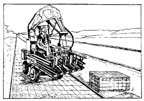
6.13. Small-sized paving elements are laid in the cover by slab-laying machines (application) or manually, and paving slabs with the help of automobile and pneumowheel cranes, forklifts with attachments.
When laying plates with a side size of 100 cm, they are aligned using rigging hooks after the lower plane of the plate is lowered by a crane 2 to 3 cm below the upper plane of the laid adjacent plates. Plate distortions and breaking off the edges of the plates are not allowed.
6.14. Alignment of laid plates is done by lightly tapping with wooden rammers. The ledges in the seams of adjacent plates should not exceed 2 mm. A roll of sand or sand-cement mix formed at the edges of the plates is cut with a manual template.
6.15. It is recommended to seal prefabricated coatings, especially for large areas, after preliminary settling of the products and leveling them with wooden hammers using vibrating plates developed by SDM Zapchast-Service and SDM Gidroprivod CJSC. In fig. 2 types of vibrating plates for compaction of prefabricated coatings are shown, one of which is equipped with a frame with three rollers, the surface of which is wrapped with special rubber material. The width of the sealing surface of such a plate is 700 mm. The characteristics of the base plate are given in table. .
6.16. When installing prefabricated coatings in the winter, it is advisable to prepare the subgrade, the underlying layer and the base for the coating before a stable negative temperature occurs. The leveling layer is laid on the prepared base immediately before installation.
6.17. When laying slabs on a base of low-cement rolled concrete in winter, its surface must be thoroughly cleaned of dirt, snow and ice and then warmed up. To facilitate the removal of ice cover, it is recommended to thaw it with a CaC solutionl 2 applied to the surface in an amount of 1 l / m 2. It can be thawed using hot sand heated to 180 - 200 ° C with a thickness of 5 - 7 cm, followed by its removal.
6.18. A cement-sand mortar with a thickness of up to 20 mm is laid on a cleaned and heated concrete base.
6.19. Sealing of joints is recommended only in spring. If it is necessary to fill the joints in winter, it is necessary to preheat the joints of the slabs and fill them with sand-cement mixture heated to 35 ° C.
6.20. Work on the installation of sidewalks during heavy snowfall is terminated. The preparatory sections of the leveling layer are covered with mobile awnings, material of the “mandrel” type with a film cover or special mats. It is not recommended to lay the plates at temperatures below -15 ° C.
Table 8
Characteristics of the VP-070 vibrating plate manufactured by SDM Zapchast-Service and ZAO SDM Gidroprivod
|
The width of the sealing surface, mm |
|
|
Effective working surface, m 2, not less |
0,13 |
|
Compaction depth, not less |
12,0 |
|
Compaction force, kN, not less |
|
|
Vibration frequency, Hz |
|
|
Productivity, theoretical at 1 pass, m 2 / h |
|
|
Plate travel speed, m / min |
|
|
Dimensions of a vibrating plate, mm, no more |
|
|
length |
1000 |
|
width |
|
|
height |
|
|
Dimensions in transport position |
790 ´ 380 ´ 610 |
|
Type of oil vibrator |
|
|
The amount of oil in the vibrator, ml |
|
|
engine's type |
Honda (Robin) |
|
Engine power, kW / hp |
2,9/4,0 (2,6/3,5) |
|
Type of fuel |
AI-92 gasoline |
|
Type of engine cooling |
Air |
|
Type of engine oil: |
SAE 10 W 30, SAE 20W |
|
Engine fuel tank capacity, l, not less |
2,5 (2,8) |
|
Operating time without refueling, h |
|
|
Water tank capacity, l |
7. QUALITY CONTROL OF WORKS
7.1. Work on the construction of structures made of plates and paving elements should be performed in accordance with the requirements of the project, Construction Norms and Regulations, current regulatory and technical documents or these technical recommendations.
7.2. Work on the arrangement of sidewalks, platforms, paths, etc. should be carried out with their operational monitoring with the help of technical personnel of construction companies and periodic monitoring by specialized laboratories.
7.3. The laboratory should regularly monitor the quality of materials and products, evaluate their compliance with current GOSTs and Technical Recommendations.
7.4. When accepting structural layers of sidewalks, platforms, pedestrian streets, paths, compliance with the approved design of the device of the underlying layer, base, drainage devices and drainage should be checked. Verification is carried out on acts on hidden work, work logs and laboratory data.
7.5. When accepting the finished coating check:
Correspondence of the longitudinal and transverse profile of the coating to the project (carried out by control leveling);
The width of the seams and the quality of their seal;
Excess of adjacent plates;
If damaged slabs or paving elements are present, they must be replaced.
7.6. Deviations from the design dimensions when installing prefabricated coatings:
Coating width ± 5 cm;
Clearance under a three-meter rail ± 3 mm;
The excess of the faces of adjacent panels of prefabricated coatings ± 3 mm.
8. SAFETY REQUIREMENTS
8.1. Safety measures at construction sites must be observed in accordance with the requirements of the norms and rules of SNiP 12-03-2001 “Safety at work in construction”.
8.2. Sanitary facilities at the facilities should be equipped in accordance with the hygiene requirements of the Ministry of Health of Russia.
8.3. Allowed to work at least 18 years of age who have undergone a medical examination, trained in an approved program of safe working methods and instructed directly at the workplace. Testing of knowledge is carried out annually by a commission, after which certificates are issued to workers.
8.4. The observance of safety regulations during construction is the responsibility of the chief engineer of the manufacturer.
8.5. An examination of the safety knowledge of engineering workers should be carried out annually. In case of unsatisfactory knowledge, the chief engineer of the company must not allow engineering and technical personnel to supervise the work.
8.6. Workers must be provided with special clothing and serviceable hand tools in accordance with the requirements of GOST 28010-88.
8.7. During winter work, periodical breaks of 10 minutes are set for heating workers at temperatures from -20 ° C to -30 ° C and a complete cessation of work at temperatures below -30 ° C.
8.8. The working area must be protected. At nightfall, red warning lights should be installed in the work area. Lighting lamps with a power of up to 200 W are suspended at a height of 2.5 - 3 m, and more than 200 W - at a height of 3.5 - 10 m.
8.9. Persons engaged in the preparation and application of film-forming materials should work in overalls, tarpaulin mittens and safety glasses.
It is forbidden to smoke and use open flame when working with film-forming materials containing flammable substances.
8.10. When transferring products and other materials manually during the construction, repair and reconstruction of sidewalks, sites, walkways, etc., the limit norm for each worker should not exceed 50 kg.
8.11. Responsibility for the good condition of the machines and mechanisms used in the construction, lies with the head of the site.
9. ENVIRONMENTAL PROTECTION
9.1. When carrying out construction of structures with coatings from prefabricated elements, as well as when performing their current and major repairs, measures and work to protect the environment should be carried out in accordance with the requirements of SNiP 22-01-95 and SNiP 22-02-2003.
9.2. In the preparatory period before the construction of sidewalks, platforms, pedestrian streets, etc. from concrete products follows:
To fence the site of work;
Transplant trees from the building under construction;
Protect the remaining trees next to sidewalks, sites, etc. to avoid damage to them;
To equip on site construction sites with fuel and water for road-building machines.
9.3. In the process of construction and reconstruction of sidewalks, it is necessary to ensure the safety of the population in the territory adjacent to the object, to prevent air pollution.
9.4. All engineers and workers should be instructed on environmental protection within the facility under construction.
9.5. The territory of the construction site after completion of the road construction should be cleaned of construction waste and planned according to design marks.
10. OPERATION OF THE SIDE
10.1. To maintain the sidewalks in good condition should be carried out:
Maintenance;
Overhaul.
10.2. The content of prefabricated pavement coverings includes regular maintenance work to maintain them in good order and clean throughout the year, ensuring normal conditions for pedestrian movement.
10.3. Maintenance is carried out every 3 years and includes work to eliminate minor defects, oil stains, cracks and destruction of individual plates and small-sized paving elements.
10.4. Oil stains are removed using various adsorption powders, including household detergents. Aerosol paints applied to concrete products using a spray gun are removed with acetone.
Bitumen from concrete slabs is removed by mechanical means or manually. A mixture of gasoline with oil is applied to the remaining stain and the repaired area is covered with a plastic film to reduce the evaporation of gasoline.
10.5. Cracks, chips, potholes, cavities, shells or peeling of the surface of concrete products, includingcolor, depending on the type of defects and the amount of reconstruction work can be eliminated using various compositions and technological methods in accordance with the requirements of TR 101-99 "Technical recommendations for the use of concrete with the material" Aquatron-6 "for road construction" (GUP " NIIMosstroy ").
10.6. At current repair, if necessary, level the base. Destroyed slabs are removed and replaced with new ones, which are placed on a sand-cement mortar or a dry cement-sand mixture.
In this case, the seams between the laid plates are cleaned with compressed air and poured with a 3: 1 sand-cement mortar to the height of the seam.
10.7. Overhaul involves the complete or partial replacement of structural elements of prefabricated coatings of plates or small-sized elements, base, underlying layer. At the same time, the subgrade must be additionally compacted (K opl.³ 0,98).
10.8. Structural elements for prefabricated coatings with overhaul performed in the same way as during construction (see sections -).
Annex 1
Characterization of small elements
|
Physico-mechanical properties of plates |
One rev. |
Characteristics of elements for lattice plates with cells, mm |
|||||||||||||||||||||||||||||||||||||||||||||||||||||||||||||||||||||||||||||||||||||||||||||||||||||||||||
|
110´ 110 |
110´ 210 |
||||||||||||||||||||||||||||||||||||||||||||||||||||||||||||||||||||||||||||||||||||||||||||||||||||||||||||
|
Item Sizes |
100´ 100 |
100´ 200 |
|||||||||||||||||||||||||||||||||||||||||||||||||||||||||||||||||||||||||||||||||||||||||||||||||||||||||||
|
Product weight |
|||||||||||||||||||||||||||||||||||||||||||||||||||||||||||||||||||||||||||||||||||||||||||||||||||||||||||||
|
Concrete volume |
|||||||||||||||||||||||||||||||||||||||||||||||||||||||||||||||||||||||||||||||||||||||||||||||||||||||||||||
|
Quantity in 1 m 3 |
|||||||||||||||||||||||||||||||||||||||||||||||||||||||||||||||||||||||||||||||||||||||||||||||||||||||||||||
|
Class (grade) of concrete in compressive strength |
35, 40 (450, 500) |
35, 40 (450, 500) |
|||||||||||||||||||||||||||||||||||||||||||||||||||||||||||||||||||||||||||||||||||||||||||||||||||||||||||
|
Concrete strength at the time of product release in: |
% of brand strength |
||||||||||||||||||||||||||||||||||||||||||||||||||||||||||||||||||||||||||||||||||||||||||||||||||||||||||||
|
summer time |
|||||||||||||||||||||||||||||||||||||||||||||||||||||||||||||||||||||||||||||||||||||||||||||||||||||||||||||
|
winter time |
|||||||||||||||||||||||||||||||||||||||||||||||||||||||||||||||||||||||||||||||||||||||||||||||||||||||||||||
|
Concrete brand for frost resistance in saline solutions |
not less than 200 |
||||||||||||||||||||||||||||||||||||||||||||||||||||||||||||||||||||||||||||||||||||||||||||||||||||||||||||
|
Water absorption |
COMPLEX OF PERSPECTIVE DEVELOPMENT OF THE CITY TR 72-98 MOSCOW - 1998 Technical recommendations for the construction and construction technology of roads, sidewalks, sites in the territories of cultural and domestic purposes were developed by candidates of technical sciences V.M. Goldin, L.V. Gorodetsky, R.I. Bega (laboratory of road construction NIIIMosstroy) with the participation of the State Institution "Mosstroilicencia". The recommendations are based on research carried out by the Road Construction Laboratory of NIIMosstroy, as well as the experience gained by road construction organizations in Moscow and other Russian cities. The recommendations were developed for the first time and are mainly intended for construction in areas of new housing construction, although they can be successfully used for the central areas of the city for the overhaul of social and cultural facilities. 1. GENERAL PROVISIONS1.3. Coatings of roads, platforms, sidewalks, and blind areas are arranged in two types: monolithic - from cast concrete mixture, prefabricated - from small-sized and large-sized concrete and reinforced concrete slabs. 1.4. The width of the carriageway is accepted 3.5 and 5.5 m (in some cases - 6-7 m). The width of one pedestrian lane is 0.75 m. 1.5. The construction of roads, sidewalks, sites, and a blind area at cultural facilities should be carried out at positive air temperatures. In the case of construction of individual elements of roads, sidewalks, platforms and blind areas at negative air temperatures, one should use the recommendations of the “Instructions for the construction technology of urban roads in winter (VSN 51-96). 1.6. Reinforced concrete slabs are used for coating roads and sites in accordance with the requirements of GOST 21924.0-84 - GOST 21924.3-84 of the following configurations: P - rectangular; PB - rectangular with one combined side; PBB - rectangular with two combined sides; PT - trapezoidal; PS is hexagonal; PShD - hexagonal axial diagonal; PShP - hexagonal axial transverse; DPSh - the diagonal half of the hexagonal plate; PPSh - the transverse half of the hexagonal plate. 1.7. In accordance with GOST 17608-91, the following plates are used for pavement coatings: square (K), rectangular (P), hexagonal (W), curly (F) and decorative road elements (EDD). 1.8. Concrete and reinforced concrete bead stones are used in accordance with GOST 6665-91 of the following types: BR - straight ordinary; BU - straight lines with broadening; BUP - straight lines with intermittent broadening; BL - straight lines with a tray; BV - entry; BC - curved. 1.9. In crowded areas of cultural and domestic purposes, reversal areas are arranged for vehicles. Headland diagrams are affixed to. 2. DESIGNS2.1. The construction of roads, sites include the following elements: shallow drainage; the underlying layer; side stone; base; coating. Sidewalk structures consist of a base layer, base and cover. Design options are presented at. 2.2. The shallow drainage is designed to drain the pavement and the upper part of the subgrade. The drainage structure consists of a drainage layer and tubular drains laid on a planned bottom of the rooftop. 2.3. Expanded clay pipe-filters, perforated asbestos-cement, ceramic and polymer drainage pipes can be used as drains. Joints and drainage holes of drains protect from dusting by couplings and filters, which can be used stone materials, non-woven synthetic materials, as well as fiberglass.
3.14. The compacted underlying sand layer should have a design thickness, the deviation from the design should not exceed ± 1 cm, and the compaction coefficient should be at least 0.98. The maximum clearance under the three-meter rail should not exceed 1 cm. The longitudinal and transverse slopes should be in accordance with the design. 3.15. Before installing the side stone on a leveled and compacted sandy underlying layer, formwork is installed with a height of 20 cm and a width of 20 cm greater than the width of the side stone. 3.16. Installation of meter side stones is carried out by hand and manually with the help of a tick or U-shaped device. The installation diagram of meter side stones using the indicated devices is presented on. 3.17. The side stone is mounted on a concrete base 10 cm thick along a cord stretched between the metal pins. The side stone is deposited to the level of the stretched cord with a wooden rammer. After installing the side stone, a concrete cage is arranged on both sides of the stone in the formwork to a height of 10 cm. 3.18. Long side stones are mounted on a sandy foundation with truck cranes with a lifting capacity of 3-5 tons or with TO-30 pneumatic wheel loaders with a carrying capacity of 2.2 tons and PK-271 with a carrying capacity of 2.7 tons. 3.19. The seams between the side stones are filled with a cement-sand mortar with a composition of 1: 4, after which they are embroidered with a cement-sand mortar with a composition of 1: 2. 3.20. For paving roads and sites, the base is usually made up of compacted crushed stone mixtures or rolled low-cement concrete mixtures. On is a general view road construction from plates with two side stones. 3.42. Installation of the coating should be carried out as far as possible "from the wheels" without intermediate storage of plates at the facility. Laying of plates is carried out by automobile and pneumatic wheel cranes from the finished coating using the “on their own” method. 3.43. With a gable profile, installation is carried out from the axis of the road to its edges. With a single-slope profile, laying is carried out in transverse rows from edge to edge towards the slope. 3.44. The ledges in the seams should not exceed 5 mm. The width of the seam between adjacent plates is allowed from 6 to 8 mm. The joints between the plates should be cleaned of dust and dirt and filled with the heated Izol-2 bitumen mastic of the following composition by weight (in%): bitumen 40 / 60-75; rubber crumb - 20; coumarone resin - 5. 3.45. The technological sequence for the construction of coatings from small-sized concrete slabs is the same as in the construction of coatings from large-sized slabs. Small-sized plates should be laid on the prepared base with special pavers.
Fig. 3.2. General view of the road structure of slabs with two side stones: a) prefabricated construction of plates; b) overall dimensions of the plate with sides; 1 - plate with sides; 2 - sand; 3 - soil, 4 - mounting loops; 5 - a metal slip; 6 - embedded parts; 7 - seam with mastic "Izol-2" 4. TECHNOLOGICAL SEQUENCE OF CONSTRUCTION OF PAVEMENTS, PEDESTRIAN ROADS AND AREA4.1. Sidewalks and footpaths should be located: between the roadway and the building; between the roadway and the lawn; between lawns; in the strip of green spaces. 4.2. During the construction of sidewalks, pedestrian paths, the same requirements are imposed on the subgrade, sandy underlying layer, as in the construction of the roadway. 4.3. For the installation of monolithic concrete coatings and the manufacture of prefabricated slabs, concrete with frost resistance of at leastF 150 with a tensile strength at bending of 40-45 kgf / cm 2, compression - 300-350 kgf / cm 2. 4.4. Small-sized slabs are placed in the pavement coating with slab-laying machines () or manually, and large-sized ones using automobile and pneumatic wheel cranes. 4.5. The layout diagrams of slabs in the pavement cover are presented, and the layout patterns of curly paving elements are presented. 4.6. To comply with the slope and evenness of the coating when laying small-sized plates, it is recommended: Arrange a milestone along the side stone or across the sidewalks; Laying slabs start from the side stone and lead towards the slope; To level the laid plates with a light tapping with a wooden hammer on the wooden laying lying on the plate; The width of the joints between the plates should be within 5-8 mm; The excess edges of adjacent plates should not be more than 2 mm. 4.7. The joints between the plates are filled with a cement-sand mixture. Expansion joints are arranged with a width of 10 mm through 50 m. The expansion joints are sealed with bituminous mastic or insul. The location of the expansion joints in the pavement is shown. 4.8. The evenness of the coating is checked by a 3-meter rail in at least 20 m, the clearance under the rail should not exceed 3 mm. 4.9. The blind areas should be arranged at all buildings being erected. The blind area is 0.75 m, with a transverse slope from the building of at least 20%about . 4.10. The construction of the blind area can be of two types. Type I . On a compacted subgrade (K unit 0.98-1.0), a sandy underlying layer 10 cm high, a polyethylene film and a cast concrete layer 10 cm high are laid. Type II . On a compacted subgrade (K unit 0.98-1.0), a sandy underlying layer 10 cm high and reinforced concrete slabs of the following sizes are laid: 3.0x0.75x0.08; 1.5x0.75x0.08; 0.75x0.75x0.8; 0.3x0.75x0.08 (in cm). 4.11. The indicated standard sizes of reinforced concrete slabs (album "Precast concrete pavement slabs", developed by NPO Prokatdetal and NIIMosstroy in 1987) make it possible to set up blind areas at the buildings under construction of any configuration.
Fig. 4.1 . Slab
Fig. 4.2. Layouts of paving slabs
Fig. 4.3. Layouts of curly concrete small-sized paving elements (dimensions are given in mm)
Fig. 4.4. The location of the expansion joints in the pavement 5. QUALITY CONTROL OF CONSTRUCTIONQUALITY OPERATION CONTROL DIAGRAM
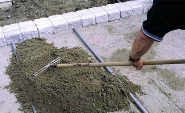
Road builders present to the customer passports for the used building materials, parts, mixtures, as well as certificates for the high-quality construction of the subgrade, sandy underlying layer. 6. SAFETY REQUIREMENTS6.1. Persons not younger than 18 years old who have passed a medical examination, trained in the safe methods of work program, received a certificate of exams and instructed directly at the workplace are allowed to work on the construction of roads, sites, sidewalks, and the blind area. Checking the knowledge of workers is carried out annually by a special commission. 6.2. All prepared and mechanized work should be carried out under the direct supervision of the engineering and technical workers appointed by order. 6.3. Workers must be provided with special clothing and serviceable hand tools in accordance with applicable standards. 6.4. At construction sites, sanitary facilities should be equipped, provided with first-aid kits with medicines and first-aid equipment, drinking boiled water. 6.5. Responsibility for observing safety measures during the construction of roads, sites, sidewalks, and the blind area lies with the chief engineer of the construction department and the manufacturer of the work. 6.6. During installation work on the installation of a coating of large-sized slabs, workers must be outside the danger zone enclosed within a circle whose radius is 5 m more than the outreach of the crane jib. 6.7. To ensure the safety of work when laying plates, riggers must use special hooks 1.5-2.0 m long. 6.8. When delivering concrete mixes with concrete mixers, the following rules must be observed: When moving along the side of the road, all workers should be on the opposite side of the road; It is not allowed to approach them until they stop completely; When moving concrete mixer trucks (especially in reverse), a worker located in a safe area should give signals to the driver. 6.9. Persons engaged in the preparation and application of film-forming materials on the concrete coating must work in overalls, tarpaulin mittens and safety glasses. 7. ENVIRONMENTAL PROTECTION7.1. By the end of the construction of buildings, sports facilities, playgrounds and roads in the areas of social and cultural life, the rest of the area allocated for the construction of the facility should be landscaped. 7.2. To determine the location of trees in the form of alleys, ordinary, group or single plantings and shrubs in the form of hedges, geodetic work should be carried out to accurately comply with the working drawings of the approved project for landscaping the object. 7.3. When landscaping an object, considerable attention should be paid to the choice of plant species for green spaces. In this case, the climatic, soil and hydrological conditions of the landing area, as well as the features of its planning and development, should be taken into account. In conditions of the city of Moscow, trees with a dense crown should most often be used: linden, birch, maple, poplar, larch, as well as fruit trees: apple, cherry, pear. From shrub species, acacia, jasmine, lilac, etc. should be used. 7.4. The distances between trees and shrubs, as well as the range of planting material should be determined in the landscaping projects of the facility. 7.5. For sowing the lawn, mixtures of herbs should be used, in particular a mixture of common comb, meadowgrass, English ryegrass and red fescue. 7.6. The longitudinal and transverse slopes of the erected lawns should be directed towards the constructed roads, thereby all wastewater and melt water fall into the rain gates of the road gutter. 7.7. In winter, clearing roads from snow should be carried out by motor graders, bulldozers, and mechanical brushes. The use of various salt solutions for removing snow from roads is prohibited. Paths from paving slabs are not only a practical landscape solution, but also a very attractive element that can transform both a section of a private household, and a park or square. But in order to extend the lifespan of sidewalks, when building them, certain rules must be followed, starting with the marking and ending with the finishing of the seams. And of course, the tile itself and the materials from which it is made play a significant role. Pavement path in the garden of a private house MaterialsThe device tracks, paved with tiles, involves the use of various materials:
Among the produced types of tiles, you can even get confused when choosing the best option Tile selectionPaving slabs are produced in two ways, which affect its main indicators, in particular - strength. Vibrocast tiles have low strength, vibropressed - increased. Therefore, for inaccessible places, mainly in the private sector, the choice of vibrocast paving slabs is justified. Accordingly, vibropressed can be used in public places when arranging tracks and even parking lots. To test the strength, you need to hit the tiles against each other. A sign of strength will be a loud sound. Deaf speaks of fragility. About colored paving slabs, it is important to know that it contains expensive coloring matter. Therefore, acquiring it, you need to pay attention to the cost. It cannot be very low - it is a sure sign and low quality. You need to purchase on average 10% more than the quantity required for the calculations. Such a reserve is pledged, providing for a waste due to the presence of marriage in the packaging, as well as a reserve for trimming the products necessary during installation. This is especially important when laying is carried out according to a complex scheme, or the contour of the sidewalk is planned of complex shape, with bends. InstrumentsThe construction of paved paths is a rather complicated technological process. Its implementation involves the presence of special tools and devices. So, for the installation of sidewalks it is necessary to prepare:
What is useful from tools Work sequenceInstallation of sidewalks consists of several sequential operations:
Contour breakdownBefore starting work on paving the pavement, it is important to check the slope of the surface. It should be flat (otherwise it will have to be leveled) and have a slope of about 2-5 degrees (to ensure rainfall runoff). It will be located along or across the sidewalk - it is not critical. Then, with the help of a rope and pegs, mark the contour of the future sidewalk. Foundation preparationA shovel is removed from the ground layer with a thickness of 15-20 cm. (In the event that an increased load is expected on the paving slabs, the layer thickness can be up to 50 cm.) The resulting base is carefully leveled with a mop or rake. In the event that the soil at the base is loose, its surface must be wet and compacted.
Preparing a place for the future track Bearing layerInstallation of bordersThe next step in the construction of sidewalks is the installation of borders. Install them on a cement mortar. First, using a cord and pegs, mark the outline along which the border will be installed, and also set the desired level, taking into account the slope. Grooves are pulled out for subsequent pouring of concrete. For tracks with a complex configuration, the border can be cut off with the help of a grinder as needed and set in segments of different lengths, following a given contour. At the same time, in the places of bends, the pegs during marking are installed at a shorter distance than in straight sections.
The border will protect the tile from shifts, and the sand from shedding Mounting layerThe prepared base of the sidewalk is covered with fine sifted sand, (the layer should be about 5 cm thick). Next, the sand is leveled using a rake and the rules. After this, the surface must be thoroughly shed with water (at least 10 liters per square meter). Let the sand settle - a few hours if the weather is sunny, and about a day - if it is cloudy. After that, the sand is compacted and carefully leveled. Now the surface is prepared directly for laying paving slabs. It is permissible to do only sand, without a layer of rubble, however, this design is suitable for places with a small amount of precipitation and otherwise it will not be able to provide sufficient drainage.
With this method, an additional formwork device from the boards is not thinner than 4 cm. After the concrete has hardened, the formwork can not be dismantled.
Sand distribution along the path Laying tilesThe absence of sagging or protruding sections and good drainage will depend on the quality of the previous work. However, the installation phase is no less responsible. It is important to comply with the intended styling pattern, not to violate the level, to sustain the size of the seams. To do this, you must follow a few rules:
The laying process of the base material In order to accurately withstand the distance of the seams, before starting laying the first row, they stretch the cord along the entire width and length of the object. Laying begins, adhering to these cords as guides. The accuracy of the location of the seams is checked in every third row. Each tile is laid using a wooden hammer or a special mallet. Twice for every 10 square meters, using the rule, they control the horizontal of the laid tile. Detected defects are immediately eliminated. For cutting plates use a grinder. Sealing and sealing jointsDraft styling is ready. Now the surface is sprinkled with fine river sand, cleaned of organic compounds (so that weeds do not germinate through it in the future) and fill the joints between the tiles. It uses a broom or brush with hard bristles. The paved surface is simply swept in different directions. If all the tiles used are the same gray, - sand can be mixed with cement - for greater laying stability. However, cement is not suitable for colored tiles - it will be rather difficult to wash off such a mixture, so it is more advisable to use just sand.
Vibropress for tamping paving slabs Now, using a vibrating plate or other device, ramming the entire surface. Excess sand is carefully washed out of the hose through a divider. If required, these two operations are repeated. To help beginners video with a description of the whole process: ExploitationThe main care for the laid paving slabs is the timely removal of dirt and dust - periodic washing off. But the track, lined with colored tiles, will have to be washed with the help of special detergents. Because it shows more clearly not only dirt, but also black tire marks. In winter, sidewalks are cleaned with a broom or wooden shovel. To clean the surface of ice, it is unacceptable to use a metal shovel and especially scrap. Snow removal equipment must be equipped with a protective nozzle. setPostViews (get_the_ID ()); ?\u003e
The production team and the possibilities of the jack of all trades, of course, differ, but not so much as to assert that in the first case the quality of the coating will be better. The paving technique remains unchanged in both cases, and routing paving of sidewalks, even when not fixed on paper, determines the sequence of actions of the master, if he decided to independently work with paving tiles. A trench is dug under the curb, then it is thrombosed by a rammer. The border is installed on a cement mortar. Preparation of materials and tools
The basic principles of tile laying technology: preparing the bed, providing drainage, an even basis for high-quality fixing of paving slabs. Everyone can make a small area of \u200b\u200bpaving if they act according to the technological scheme. Before the garden, courtyard path or parking place of a personal car takes on the form and strength that, apart from the selected materials, their proper arrangement can provide, the owner of the site will have to work hard. Without building a blueprint (plan) of future sidewalks, unless, of course, the owner has decided to create something extraordinary, you can do it. If it is planned to create a track or site according to a special, individual design, unusual shape, color schemes or at different levels, then a diagram should be drawn up with reference to other objects, and only after that marking of sidewalks on the ground is done. A compiled map will save the owner from unnecessary alterations, small or significant. First you need to prepare tools and fixtures. If the routing for a solid team of stackers contains, in addition to tools, sophisticated equipment (for example, a vibrating plate), then the home foreman will have to do without it. In order to need:
In order to further strengthen the base, a concrete screed is placed on top of it.
The number of paving slabs, curbs, cement, sand, gravel or gravel can only be calculated after marking the track on the ground. It’s good to take care in advance of the necessary footage of geotextiles, for example, black plastic film. The choice of not only paving slabs, but also the base material depends on certain factors. These include the load to which the track will be subjected (pedestrian or parking for the car). Of course, the greater mechanical stresses the structure will undergo during operation, the stronger it should be. Adequate strength can only be achieved when it is kept to the smallest detail. Back to the table of contents Work sequence
Modern paving slabs are made in a huge assortment. At the moment, there are two main ways of its manufacture - vibrocompressed and vibrocast. Pegs and twine are taken. Stretched between the pegs twine "drawn" the border of the track. The height of the twine above ground should correspond to the line of the upper surface of the future sidewalk. The marking is fixed: it is removed only after the paving slabs are laid. It is necessary to prepare the foundation of a future track or site. Removed sod or the remnants of the previous coating to a depth of 20-30 cm. If the soil is loose, the depth will have to be increased. The plane is leveled, roots and seeds are removed, if possible. The soil is compacted by tamper. If necessary, in the process of tamping, it is watered. At this stage, the main slope is marked using the level: transverse, longitudinal or longitudinal-transverse. This is done so that rain (or melt) water does not stagnate on the track: in addition to inconvenience, it can lead to premature failure of the coating. To do this, with the help of a level and a long rail, a general slope of the track is planned. If the track is made without a general slope, it is more difficult to lay: you will have to create two small slopes from the central longitudinal line to the edges, that is, you will need to measure and bring to the required level of slope of each paving slab. The next stage is the creation of a border. In rare cases, the curb is set after the track itself is ready, but then, even with very careful work, the coating made with such difficulty can be damaged. Therefore, the work schedule provides for the specified sequence. The easiest solution is to install finished curb stones on a concrete pad. It is more difficult, but cheaper to prepare the formwork and cast it from concrete. The main purpose of the curb is to prevent the paving stones from creeping during operation. It is also needed for technological purposes: it is from him that tile laying begins.
Strings tied at the correct height will not allow you to miss. | ||||||||||||||||||||||||||||||||||||||||||||||||||||||||||||||||||||||||||||||||||||||||||||||||||||||||||||