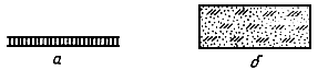
The symbol of the brickwork. Designation of materials in the drawings
GOST 2.306 - 68
All the parts that are depicted in the technical drawings represent certain geometric bodies and their combinations. They should be made of certain materials, in accordance with the requirements laid down during their development.
View material indicated in the title block of the drawing. In those cases when the cross-section must be indicated on the technical drawing, the material is indicated graphically, depending on what type it is.
One of the main requirements for graphic designations in sections of materials, is that the details should be easily distinguishable, the type of material should be shown so that the drawing is not difficult to read.
The main normative documentwhich sets the application rules materials in sections and their graphic representation, is GOST 2.306 - 68. It is valid for all industries and construction.
It is allowed to apply additional designations of materials not provided for by the standard, explaining them in the drawing.
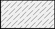
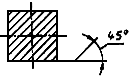
According to the standard, all parallel hatching lines must be applied at an angle of 45 ° to the image axis, its contour or to the frame of the drawing itself.

Hatching at an angle of 45 ° relative to the image contour line

Hatching at an angle of 45 ° to the image axis

Hatching at an angle of 45 ° to the lines of the drawing frame
Hatching lines should be drawn with a slope either to the right or to the left, however, so that its direction at all sections details, was the same, and regardless of the number of these sections, or the number of sheets of drawings.
The frequency of the hatching lines (i.e. the interval between them) is selected depending on factors such as the area of \u200b\u200bthe shaded surface, as well as the need for a variety of hatching cross-sections of adjacent parts of the part. For all sections of the same scale that a part may have, the distance between the applied strokes should be the same. According to the standard, the distance between the dashed lines can be in the range of 1 to 10 millimeters, depending on whether it is necessary to diversify the hatching of adjacent surfaces and on what its area is.
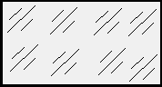
In those cases when the lines of hatching carried out at an angle of 45 ° coincide in their direction with the axial lines or contour lines, then they should be carried out at an angle of either 60 ° or 30 °.
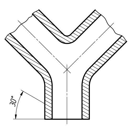
Hatching at an angle of 30 °
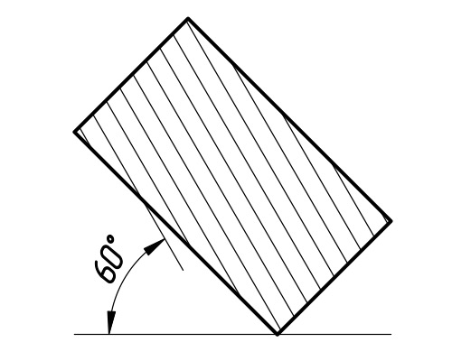
60 ° hatching

Incomplete hatching
Those cross-sectional areas that have a narrow and long shape (for example, rolled, stamped, and other similar details), and whose width at the selected drawing scale does not exceed 4 millimeters, are completely shaded only at the contours of the holes and at the ends. The rest of the area is indicated by shading in several places, in small sections. Glass shading is recommended to be applied with an inclination from 15 ° to 20 ° to the line of the largest side of the section contour.

Black sectional area
with a width of less than 2 mm
If the width sections is less than 2 millimeters in the drawing, then, according to the current standard, it is allowed to depict blackened, and the gaps between adjacent sections must be at least 0.8 mm wide. As for the construction drawings, then they are all sections a small area is allowed to be depicted as metal sections or not at all designation, and its concrete material is simply indicated by an inscription on the drawing field.
The distance between the hatching lines
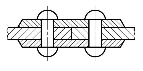
If it is necessary to depict a cross section of two adjacent parts in the drawing, then for one of them the slope of the dashed lines to the right is selected, and for the other to the left. Such a technique is called drawing in the opposite direction.
Shift hatch lines in one section
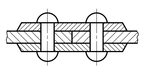
If the hatching of sections of adjacent parts is done in a “cage” way, then the distance between the lines in each of them should be different. In cases where shading of the same slope is used, the distance between the lines on different sections should be different. In addition, to highlight the line can be shifted in one section relative to the cross section of another, while not changing the angle of their inclination.

Hatching near the section contour
If the area sections large or if the soil profile is indicated on the drawing, then the indication section designations a narrow strip of uniform width directly at the contour.
ESKD GOST 2.306-68 Designations of graphic materials and the rules for their application on the drawings
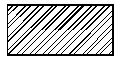
The graphic designation of the material in sections and in a view is a hatching performed by thin solid lines. The hatching form in accordance with GOST 2.306-68 gives an idea of \u200b\u200bthe material from which the part is made.
Designations graphic materials in sections
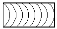
The graphic designation of materials in sections, depending on the type of materials should correspond to those given in table. 1.Table 1. Graphic designation of materials in sections
| Material | Designation |
|---|---|
| 1. Metals and carbides (General graphic designation materials in cross sections, regardless of the type of material must comply) | |
| 2. Non-metallic materials, including fibrous monolithic and plate (pressed) materials, with the exception of those indicated below | 
|
| 3. Wood | 
|
| 4. The stone is natural | |

|
|
|
|
|
|
| 8. Liquids | 
|

|
Note:
- Composite materials containing metals and non-metallic materials are referred to as metals.
- The graphic designation of clause 3 should be applied when there is no need to indicate the direction of the fibers.
- The graphic designation of clause 5 should be used to designate brick products (burnt and unburnt), refractories, building ceramics, electrical porcelain, cinder blocks, etc.
Designations graphic materials on types
When selecting materials and products in the form (facade), their graphic designations should correspond to those indicated in table. 2.Table 2. Graphic designation of materials in the form (facade)
| Material | Designation |
|---|---|
| 1. Metals | 
|
| 2. Steel corrugated | 
|
| 3. Steel expanded | 
|
| 4. Bricklaying of building and special bricks, clinker, ceramics, terracotta, artificial and natural stones of any shape, etc. | 
|
| 5. Glass | 
|
Note:
- To clarify the variety of material, in particular, materials with the same designation, the graphic designation should be accompanied by an explanatory inscription on the drawing field.
- In special building structural drawings for reinforcement reinforced concrete structures designations according to GOST 21.107-78 should be applied.
- The designation of materials on the view (facade) is allowed to be applied not completely, but only in small sections along the contour or spots inside the contour.
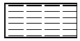
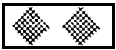
Table 3. The designation of the mesh and backfill of any material (in cross section)
Inclined parallel hatching lines should be drawn at an angle of 45 ° to the image contour line (Fig. 1) or to its axis (Fig. 2) or to the lines of the drawing frame (Fig. 3)

Figure 3. Hatching at an angle of 45
If the hatching lines drawn to the line of the drawing frame at an angle of 45 ° coincide with the contour lines or axial lines, then instead of the angle of 45 °, take an angle of 30 ° or 60 ° (Fig. 4 and 5).
Hatching lines should be drawn with a slope to the left or right, but, as a rule, in the same direction on all sections related to the same part, regardless of the number of sheets on which these sections are located.
The distance between parallel straight hatching lines (frequency) should, as a rule, be the same for all sections of a given piece performed on the same scale and should be selected depending on the hatching area and the need to diversify the hatching of adjacent sections. The specified distance should be from 1 to 10 mm, depending on the area of \u200b\u200bhatching and the need to diversify the hatching of adjacent sections.
Narrow and long sectional areas (for example, stamped, rolled and other similar parts), the width of which in the drawing is from 2 to 4 mm, it is recommended to hatch completely only at the ends and at the contours of the holes, and the remaining sectional area in small sections in several places (Fig. . 6 and 7). In these cases, the glass hatching lines (Fig. 8) should be drawn with a slope of 15 - 20 ° to the lines of the larger side of the section contour.The designation specified in paragraph 3 of the table. 1, and the designation of backfill in sections is performed by hand.
For adjacent sections of two parts, you should take the slope of the hatching lines for one section to the right and for the other to the left (counter hatching).When hatching in a cage for adjacent sections of two parts, the distance between the hatching lines in each section should be different.
In adjacent sections with hatching of the same slope and direction, the distance between the hatching lines should be changed (Fig. 11) or these lines should be shifted in one section relative to another without changing the angle of their slope (Fig. 12).

Figure 11. Hatching pattern of adjacent areas
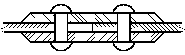
Figure 12. Hatching pattern of adjacent areas
For large cross-sectional areas, as well as when specifying the soil profile, it is allowed to mark only the contour of the section with a narrow strip of uniform width (Fig. 13).
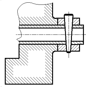
Figure 13. Hatching pattern for large areas
GOST 2.306 - 68 establishes the graphic designations of materials in sections and on facades, as well as the rules for applying them to drawings of all industries and construction.
The general graphic designation of materials in the drawings should correspond to that shown in Fig. 51
Fig. 51
Graphic designations of materials.
| Material | Designation |
 1. Metals and carbides 1. Metals and carbides | |
 2. Non-metallic materials, including fibrous monolithic and plate (pressed) materials, with the exception of those indicated below 2. Non-metallic materials, including fibrous monolithic and plate (pressed) materials, with the exception of those indicated below | |
 3. The tree 3. The tree | |
 4. The stone is natural 4. The stone is natural | |
 5. Ceramics and silicate materials for masonry 5. Ceramics and silicate materials for masonry | |
 6. Concrete 6. Concrete | |
 7. Glass and other translucent materials 7. Glass and other translucent materials | |
 8. Liquids 8. Liquids | |
 9. Natural soil 9. Natural soil |
Notes:
1. Composite materials containing metals and non-metallic materials are referred to as metals.
2. The graphic designation of the tree should be used when there is no need to indicate the direction of the fibers.
3. The graphic designation of ceramics should be used to designate brick products (burnt and unburnt), refractories, building ceramics, electrical porcelain, slag concrete blocks, etc. It is allowed to apply additional designations of materials that are not provided for by the standard, explaining them in the drawing.
Inclined parallel hatching lines should be drawn at an angle of 45 0 to the image contour line or to its axis, or to the lines of the drawing frame.
If the hatching lines drawn to the lines of the drawing frame at an angle of 45 0 coincide in direction with the contour lines, or axial lines, then instead of an angle of 45 0, you should take an angle of 30 0 or 60 0.
Hatching lines should be drawn with a slope to the right or left, but, as a rule, in the same direction on all sections related to the same part, regardless of the number of sheets on which these sections are located.
The distance between parallel, straight lines of hatching should be, as a rule, the same for all sections of the given part performed on the same scale and selected depending on the hatching area and the need to diversify the hatching of adjacent sections. The specified distance should be 1-10 mm.
LIST OF REFERENCES
1. GOST 2.001-70 General provisions of the Unified system of design documentation
2. GOST 2.104-68 Main inscriptions
3. GOST 2.301-68 Formats
4. GOST 2.302-68 Scales
5. GOST 2.303-68 Lines
6. GOST 2.304-81 Drawing fonts
7. GOST 2.305-68 Images - types, sections, sections.
7. GOST 2.307-68 Dimensioning and maximum deviations
9. Fedorenko V.A. Handbook of engineering drawing / V.A. Fedorenko, A.I. Shoshin. –15th ed., Revised. and add. - L .: Engineering, 1984. - 416 p.
10. Chekmarev A.A. Handbook of engineering drawing / A.A. Chekmarev, V.K. Osipov. - Higher school, 2000 .-- 671 p.
Annex 1
Cover sheet example

Appendix 2
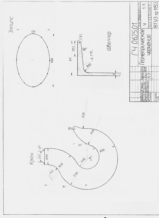
An example of the sheet "Geometric drawing"
Appendix 3
An example of the drawing "Projection drawing"
 |
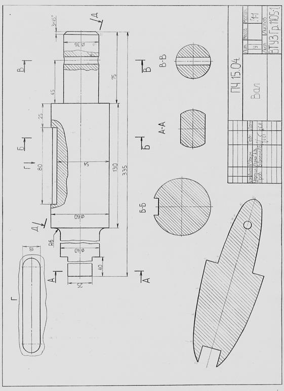
Appendix 4
An example of the implementation of the drawing "section of the shaft"
Kremleva Lyudmila Viktorovna
Guidelines for the discipline "Descriptive geometry and engineering graphics
Part 2 “Engineering Graphics”
Editor
Corrector
Computer set Kremleva L.V.
GOST 2.306-68
(ST SEV 860-78,
ST SEV 6306-88)
T52 group
STATE STANDARD OF THE USSR
Unified design documentation system
DESIGNATIONS OF GRAPHIC MATERIALS AND THE RULES FOR THEIR DRAWING ON THE DRAWINGS
Unified system for design documentation.
Graphical designations of materials and rules for their representation
Date introduced 1971-01-01
INFORMATION DATA
1. DEVELOPED AND INTRODUCED by the Committee of Standards, Measures and Measuring Instruments under the Council of Ministers of the USSR
DEVELOPERS
V.R. Verchenko, E.A. Panfilov, Yu.I. Stepanov, Ya.G. Starozhilets, B.Ya. Kabakov, L.V. Matveev, N.I. Yermin, V.N. Vzorov, M. G. Aranovsky
2. APPROVED AND IMPLEMENTED BY Decree of the Committee of Standards, Measures and Measuring Instruments under the Council of Ministers of the USSR in December 1967.
3. The standard is fully consistent with ST SEV 860-78.
4. REPLACEMENT of GOST 3455-59 and GOST 11633-65.
5. REFERENCE NORMATIVE-TECHNICAL DOCUMENTS
6. REPUBLICATION (August 1995) with Amendments N 1, 2, 3, approved in August 1980, September 1987, March 1989 (IMS 11-80, 12-87, 7-89)
1. This standard establishes the graphic designations of materials in sections and on facades, as well as the rules for applying them to drawings of all industries and construction.
1a. The general graphic designation of materials in sections, regardless of the type of materials, must correspond to Figure 1a.
(Introduced additionally, Amendment No. 1).
2. Graphic designations of materials in sections, depending on the type of materials, must correspond to those given in Table 1.
It is allowed to apply additional designations of materials not provided for in this standard, explaining them in the drawing.
Table 1
|
# G0 Material |
Designation |
|
1. Metals and carbides | |
|
2. Non-metallic materials, including fibrous monolithic and plate (pressed) materials, with the exception of those indicated below | |
|
3. Wood | |
|
4. The stone is natural | |
|
5. Ceramics and silicate materials for masonry | |
|
7. Glass and other translucent materials | |
|
8. Liquid | |
|
9. Natural soil |
Notes:
1. Composite materials containing metals and non-metallic materials are referred to as metals.
2. The graphic designation of clause 3 should be applied when there is no need to indicate the direction of the fibers.
3. The graphic designation of clause 5 should be used to designate brick products (burnt and unburnt), refractories, building ceramics, electrical porcelain, cinder blocks, etc.
(Amended edition, Amendment N 1, 2).
3. Set the following designations of the mesh and the backfill of any material (in cross section), indicated in Fig. 1.
a - mesh; b - backfill
4. When selecting materials and products in the form (facade), their graphic designations should correspond to those indicated in Table 2.
table 2
|
# G0 Material |
Designations |
|
1. Metals | |
|
2. Steel corrugated |
|
|
3. Steel expanded |
|
|
4. Bricklaying of building and special bricks, clinker, ceramics, terracotta, artificial and natural stones of any shape, etc. | |
|
5. Glass |
Notes:
1. (Excluded, Amendment No. 1).
2. To clarify the variety of material, in particular, materials with the same designation, the graphic designation should be accompanied by an explanatory inscription on the drawing field.
3. In special constructional structural drawings for reinforcing reinforced concrete structures, the designations according to # M12293 0 1200003565 24569 2352094781 247265662 4292033357 3918392535 2960271974 3534005200 147245405 ГOST 21.501-93 # S should be used.
4. The designation of the material on the view (facade) may not be applied completely, but only in small sections along the contour or spots within the contour.
5. Inclined parallel hatching lines should be drawn at an angle of 45 ° to the image contour line (Fig. 2a) or to its axis (Fig. 2b), or to the lines of the drawing frame (Fig. 2).

If the hatching lines reduced to the lines of the drawing frame at an angle of 45 ° coincide in the direction with the contour lines or axial lines, then instead of the angle of 45 °, you should take an angle of 30 ° or 60 ° (Fig. 3 and 4).

Hatching lines should be applied with a slope to the left or right, but as a rule, in the same direction on all sections related to the same part, regardless of the number of sheets on which these sections are located.
6. The distance between parallel straight lines of hatching (frequency) should, as a rule, be the same for all sections of a given piece performed on the same scale and should be selected depending on the area of \u200b\u200bhatching and the need to diversify the hatching of adjacent sections. The specified distance should be from 1 to 10 mm, depending on the area of \u200b\u200bhatching and the need to diversify the hatching of adjacent sections.
(Amended edition, Amendment No. 2).
7. Narrow and long cross-sectional areas (for example, stamped, rolled and other similar parts), the width of which in the drawing is from 2 to 4 mm, it is recommended to hatch completely only at the ends and at the contours of the holes, and the rest of the cross-sectional area in small sections in several places (Fig. 5 and 6). In these cases, the glass hatching lines (Fig. 7) should be applied with a slope of 15–20 ° to the line on the larger side of the section contour.
Hatching of all designations in this case is done by hand.
8. Narrow cross-sectional areas, the width of which in the drawing is less than 2 mm, may be shown blackened with a clearance of at least 0.8 mm between adjacent sections (Fig. 8, 9).

In construction drawings, it is allowed to designate any material on sections of a small area as metal or not to use the designation at all, making an explanatory inscription on the drawing field.
9. The designation indicated in clause 3 of Table 1 and the designation of the backfill in cross section are performed by hand.
(Amended edition, Amendment No. 1).
10. For adjacent sections of two parts, you should take the slope of the hatching lines for one section to the right, for the other - to the left (counter hatching).
When hatching "in a cage" for adjacent sections of two parts, the distance between the lines of hatching in each section should be different.
In adjacent sections with hatching of the same slope and direction, one should change the distance between the hatching lines (Fig. 10) or shift these lines in one section with respect to another without changing the angle of their inclination (Fig. 11).

11. For large cross-sectional areas, as well as when specifying the soil profile, it is allowed to mark only the contour of the section with a narrow strip of uniform width (Fig. 12).

(Amended edition, Amendment No. 1).
The text of the document is verified by:
official publication
"Unified system of design documentation.
General rules for the execution of drawings ": Sat. GOST -
M .: IPK Publishing house of standards, 1995
If the secant plane passes through the axis of the surface of revolution bounding the hole or recess, then the contour of the hole or recess in the section is shown completely (Figure 35).
Figure 35 - An example of the implementation of sections for holes
Remote Element - an additional separate image (usually enlarged) of any part of the subject requiring graphic and other explanations with respect to shape, size and other data. Figure 36 shows an example of the design of a remote element.
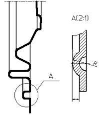
Figure 36 - An example of the design of the remote element
The external element may contain details not indicated on the corresponding image, and may differ from it in content (for example, the image may be a view, and the external element may be a cut).
When using the extension element, the corresponding place is marked on the view, section or section with a closed solid thin line - circle, oval, etc., with the extension element marked with a capital letter or a combination of an uppercase letter with an Arabic numeral on the line shelf - leader. Above the image of the remote element indicate the designation and scale at which it is made. The remote element should be positioned, as far as possible, closer to the corresponding place in the image of the object.
Conventions and simplifications - these are the rules that make the drawing simpler, more understandable and reduce the time it takes to complete it. GOST 2.305-2008 establishes the following conventions and simplifications:
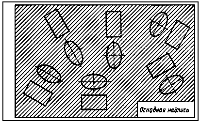
1. If the view, section or cross-section is a symmetrical figure, it is allowed to draw half of the image limited by the center line or a little more than half of the image with the clipping line drawn in the latter case (Figure 37).
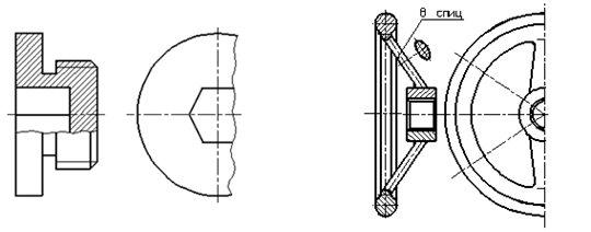
Figure 37 - An example of a simplified image of a symmetrical part
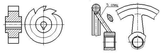
Figure 38 - An example image of an object with the same, evenly spaced elements
2. If an object has several identical, evenly spaced elements, then one or two of these elements are completely shown on the image of this object, and the remaining elements are shown simplified or conditionally. It is allowed to depict a part of the subject with proper instructions on the number of elements, their location, etc. (Figure 38).
3. On views and sections, it is allowed to simplistically depict projections of intersection lines of surfaces, if their exact construction is not required. For example, instead of curve curves, circular arcs and straight lines are drawn (Figure 39).

Figure 39 - An example of a simplified image of intersection lines of surfaces
4. A smooth transition from one surface to another is shown conditionally or not shown at all (Figure 40).

Figure 40 - An example of a simplified image of a smooth transition between surfaces
5. Parts such as screws, rivets, dowels, hollow shafts and spindles, connecting rods, handles, etc. with a longitudinal section show conditionally uncut. Balls are always shown uncut. As a rule, nuts and washers are shown uncut on assembly drawings. Elements such as flywheel spokes, pulleys, gears, thin walls such as stiffeners, etc., are shown without shading if the secant plane is directed along the axis or long side of such an element. If in such elements of the part there is local drilling, a recess, etc., then a local cut is made (Figure 41).
Figure 41 - An example of the image of local sections on the shafts
6. Plates, as well as elements of parts (holes, chamfers, grooves, recesses, etc.) with a size (or a difference in size) in a drawing of 2 mm or less are depicted with a deviation from the scale adopted for the entire image, in the direction of increase.
7. Slight tapering or slope is allowed to be shown with magnification.
8. If necessary, highlight on the drawing the flat surfaces of an object, diagonals are drawn in them with solid thin lines (Figure 42).

Figure 42 - Example of designation of flat surfaces
9. Items or elements that have a constant or regularly changing cross section (shafts, chains, rods, shaped bars, connecting rods, etc.) are allowed to be displayed with gaps. Partial and tearing images are limited in one of the following ways:
A solid thin line with a kink that can extend beyond the image contour to a length of 2 to 4 mm. This line can be inclined relative to the contour line (Figure 43);
Figure 43 - Example of a part image with a gap
A solid wavy line connecting the corresponding contour lines (Figure 44);
Figure 44 - Example of a part image with a gap
Hatching lines (Figure 45).

Figure 45 - Example of a part image with a gap
10. On the drawings of objects with a continuous grid, braid, ornament, relief, knurling, etc., it is allowed to depict these elements partially, with a possible simplification (Figure 46).

Figure 46 - An example of a relief image
11. To simplify the drawings or reduce the number of images allowed:
The part of the object located between the observer and the secant plane is depicted by a dash-dotted thickened line directly on the section (superimposed projection) (Figure 47);

Figure 47 - An example image of a part of an object,
located between the observer and the secant plane
Apply complex cuts (Figure 48);
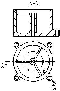
Figure 48 - An example of using a complex section
To show the hole in the hubs of gears, pulleys, etc., as well as for keyways, instead of the full image of the part, give only the outline of the hole or groove (Figure 49);
Depict in a section the holes located on the round flange when they do not fall into the secant plane (Figure 15, section AA).
Figure 49 - An example of the image of the holes
12. If the top view is not necessary and the drawing is made up of images on the frontal and profile projection planes, then with a stepwise section, the section line and inscriptions related to the section are plotted as shown in the figure (Figure 50).
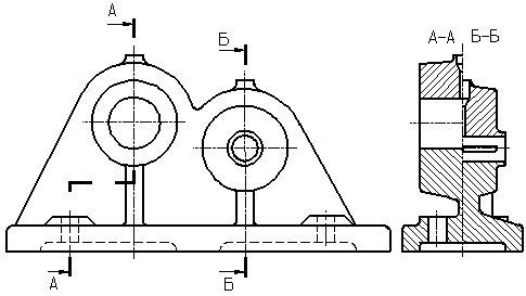
Figure 50 - An example of a combination of sections
The graphic designation of the material in sections and in a view is a hatching performed by thin solid lines. The hatching form in accordance with GOST 2.306-68 gives an idea of \u200b\u200bthe material from which the part is made.
The graphic designation of materials in sections, depending on the type of materials, must correspond to those given in table 8.
Table 7 - Graphic designation of materials in sections
|
Material |
Designation |
|
1. Metals and hard alloys (The general graphic designation of materials in sections, regardless of the type of material must comply) | |
|
2. Non-metallic materials, including fibrous monolithic and plate (pressed) materials, with the exception of those indicated below. | |
|
3. Wood | |
|
4. The stone is natural | |
|
5. Ceramics and silicate materials for masonry | |
|
7. Glass and other translucent materials | |
|
8. Liquids | |
|
9. Natural soil |
1. Inclined parallel hatching lines should be drawn at an angle of 45 ° to the image contour line or to its axis or to the lines of the drawing frame (figures. 51, 52).
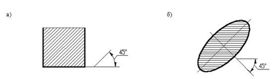
Figure 51 - Hatching direction at an angle of 45 0 to the contour line
image (a) or to its axis (b)

Figure 52 - Hatching direction at an angle of 45 0 to the lines of the drawing frame
2. Hatching lines should be applied with a slope to the left or right, but, as a rule, in the same direction on all sections related to the same part, regardless of the number of sheets on which these sections are located.
3. The distance between parallel straight hatching lines (frequency) should, as a rule, be the same for all sections of a given piece performed on the same scale and should be selected depending on the area of \u200b\u200bhatching and the need to diversify the hatching of adjacent sections.
4. The frequency of hatching should be from 1 to 10 mm, depending on the area of \u200b\u200bhatching and the need to diversify the hatching of adjacent sections.
5. If the hatching lines drawn to the line of the drawing frame at an angle of 45 ° coincide with the contour lines or axial lines, then angles of 30 ° or 60 ° should be taken instead of the angle of 45 ° (Figure 53).
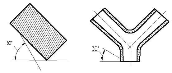
Figure 53 - Direction of hatching at an angle of 60 0 or 30 0
6. Narrow and long cross-sectional areas (for example, stamped, rolled and other similar parts), the width of which in the drawing is from 2 to 4 mm, it is recommended to hatch completely only at the ends and at the contours of the holes, and the remaining cross-sectional area in small sections in several places (Figure 54).
Figure 54 - Hatching narrow and long areas
7. Glass hatching lines should be applied with a slope of 15–20 ° to the lines of the larger side of the section contour (Figure 55).
Figure 55 - Glass shading
8. Narrow cross-sectional areas, the width of which in the drawing is less than 2 mm, can be shown blackened with a clearance of at least 0.8 mm between adjacent sections (Figure 56).
Figure 56 - Hatching with blackening
9. For adjacent sections of two parts, you should take the slope of the hatching lines for one section to the right, for the other - to the left (counter hatching).
When hatching in a cage for adjacent sections of two parts, the distance between the hatching lines in each section should be different.
In adjacent sections with hatching of the same slope and direction, the distance between the hatching lines should be changed or these lines should be shifted in one section relative to another without changing the angle of their slope (Figure 57).
Figure 57 - Example of hatching an assembly unit
10. For large cross-sectional areas, as well as when specifying the soil profile, it is allowed to mark only the contour of the section with a narrow strip of uniform width (Figure 58).

Figure 58 - Example of hatching large areas
The linear dimensions and their maximum deviations in the drawings and in the specifications are indicated in millimeters, without indicating the unit of measurement. If the drawing dimensions must be indicated not in millimeters, but in other units of measurement (centimeters, meters, etc.), then the corresponding dimensional numbers are recorded with the unit of measurement (cm, m) or indicated in the technical requirements.
For dimensions and maximum deviations given in the technical requirements and explanatory inscriptions on the drawing field, units of measurement must be indicated.
Angular dimensions and maximum deviations of angular dimensions are indicated in degrees, minutes and seconds with the unit of measurement, for example: 4 °; 4 ° 30´; 12 ° 50´30´´; 0 ° 30´40´´; 0 ° 18´; 0 ° 5´25´´; 0 ° 0´30´´; 30 ° ± 1 °; 30 ° ± 10´.
To apply dimensions, use extension and dimension lines and dimension numbers.
The total number of dimensions in the drawing should be minimal, but sufficient for the manufacture and control of the product.
Dimensional and extension lines should be made with solid thin lines. Dimension lines are limited by arrows. The size of the arrows is selected depending on the thickness S of the line of the visible contour of the object and should be approximately the same for all dimension lines of the drawing (Figure 59).
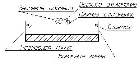
Figure 59 - Size structure
When applying the size of a straight segment, a dimension line is drawn parallel to this segment, and extension lines are perpendicular to the dimensions. The size of the arrows should correspond to the image in Figure 60.
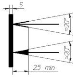
Figure 60 - Image of arrows of dimension lines
When applying dimensions of parts similar to the image in Figure 61, dimension lines should be drawn in the radial direction, and extension lines should be drawn along arcs of circles.

Figure 61 - Examples of dimensioning
When applying the size of the angle, the dimension line is drawn in the form of an arc with the center at its apex, and extension lines - radially (Figure 62).
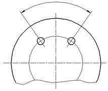
Figure 62 - Angular size
When applying dimensions, it must be remembered that all drawings, regardless of scale, indicate the actual dimensions of the product.
Dimensional numbers within the same drawing are made in the font of the same size. Dimensional numbers are applied over the dimension line as close as possible to its middle.
When applying several parallel or concentric dimension lines at a small distance from each other, it is recommended that the dimension numbers above them be staggered.
When applying the size of the diameter inside the circle, the dimensional numbers are offset relative to the middle of the dimension lines.

Figure 63 - Linear dimensioning
Dimensional numbers of linear dimensions for different slopes of dimension lines are positioned, as shown in Figure 63. If it is necessary to apply the dimension in the shaded area, the corresponding dimension number is applied on the shelf of the leader line.
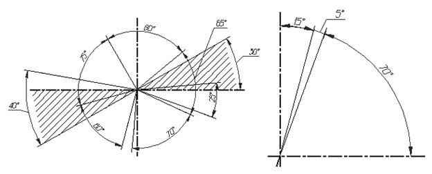
Figure 64 - Installation of angular dimensions
Angular dimensions are plotted as shown in Figure 64. In the area located above the horizontal center line, dimensional numbers are placed above the dimension lines from the side of their convexity; in the zone located below the horizontal center line - from the concavity side of dimension lines. In the shaded area, applying dimension numbers is not recommended. In this case, dimensional numbers indicate horizontally applied shelves.

Figure 65 - Dimensioning requirements
The arrows bounding the dimension lines should rest against the corresponding contour lines, or extension, or axial lines. Extension lines should extend beyond the ends of the dimensional arrows by 1 ... 5 mm. The minimum distance between parallel dimension lines should be 7 mm, and between the dimension and contour line - 10 mm and chosen depending on the size of the image and the saturation of the drawing (Figure 65).
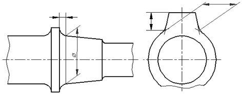
Figure 66 - Example of dimensioning
In the cases shown in Figure 66, the dimension and extension lines are drawn so that they form a parallelogram together with the measured segment.
Avoid intersecting dimension and extension lines.
It is not allowed to use contour lines, axial, center and extension lines as dimensional.
It is allowed to draw dimension lines directly to the lines of the visible contour, axial, center and other lines.
Extension lines are drawn from the line of the visible path, except when drawing dimensions on the invisible path eliminates the need to draw an additional image.
If the view or section of a symmetrical object or individual symmetrically located elements is shown only up to the axis of symmetry or with a break, then the dimension lines related to these elements are drawn with a break, and the break of the dimension line is made further than the axis or line of the break of the object (Figure 67).

Figure 67 - An example of using a dimensional line with a gap
Dimension lines are allowed to be cut off in the following cases:
a) when specifying the size of the diameter of the circle, regardless of whether the circle is depicted in full or in part, while the breakage of the dimension line is made further than the center of the circle (Figure 68);
Figure 68 - Setting the diameters
b) when applying dimensions from a base not shown in this drawing (Figure 69).
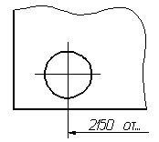
Figure 69 - Break in the dimension line when applying size from the base
When displaying a product with a gap, the dimension line is not interrupted (Figure 70).
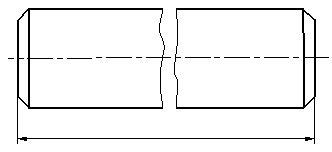
Figure 70 - Example of designation of the size when the image of the part with a gap
If the length of the dimension line is insufficient to accommodate the arrows on it, then the dimension line continues to be carried out by extension lines (or, respectively, by contour, axial, center, etc.) and the arrows are plotted as shown in Figure 71.
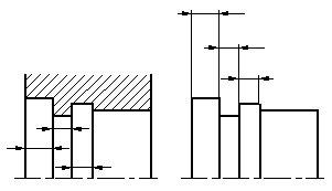
Figure 71 - Examples of the location of dimension lines
If there is not enough space for the arrows on the dimension lines located in the chain, the arrows can be replaced by serifs drawn at an angle of 45 ° to the dimension lines or clearly applied points.
If there is not enough space for the arrow due to a closely located contour or extension line, the latter can be interrupted.
The method of applying the dimensional number at different positions of the dimension lines (arrows) in the drawing is determined by the greatest readability (Figure 72).
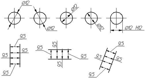
Figure 72 - Examples of applying dimensions at different positions of dimension lines
Dimensional numbers and limit deviations are not allowed to be divided or intersected by any lines of the drawing.
It is not allowed to break the contour line for drawing a dimensional number and to apply dimensional numbers at the intersection of dimensional, axial or center lines.
In the place where the dimension number is applied, the axial, center lines and hatching lines are interrupted (Figure 73).

Figure 73 - Examples of applying dimensions with a break in the axial lines (a) and hatching lines (b)
It is recommended to group the dimensions related to the same structural element (groove, protrusion, hole, etc.) in one place, placing them on the image in which the geometric shape of this element is shown most fully (Figure 74).
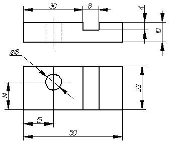
Figure 74 - Dimensioning examples
When applying the size of the radius, a capital letter is placed in front of the size number R . If, when applying the size of the radius of the arc of a circle, it is necessary to indicate the size that determines the position of its center, then the latter is depicted as the intersection of center or extension lines.
With a large radius, the center can be brought closer to the arc, in this case the dimension line of the radius is shown with a kink at an angle of 90 °.
If it is not required to indicate the dimensions that determine the position of the center of the arc of a circle, then the dimension line of the radius may not be brought to the center and offset from the center (Figure 75).

Figure 75 - Examples of applying radius size
If the radii of fillets, bends, etc., are the same in the whole drawing or some radius is predominant, then instead of plotting the dimensions of these radii directly on the image, it is recommended to record in the technical requirements a record like: “Fillet radii 4 mm”; "Internal bend radii of 10 mm"; “Unspecified radii of 8 mm”, etc.
When specifying the size of the diameter (in all cases), the sign “before Æ ».
To indicate a cylindrical surface, one should be guided by the following rule: a surface above 180 ° is defined by a diameter, less than 180 ° by a radius, in the case when the angle of the cylindrical surface is 180 °, both radius and diameter can be used to indicate it.
Before the dimension number of the diameter (radius) of the sphere, the sign is also applied Æ (R) without the inscription “Sphere” (Figure 76).
If it is difficult to distinguish a sphere from other surfaces in the drawing, then before the dimension number of the diameter (radius) it is allowed to put the word “Sphere” or the sign “○”, for example, “Sphere Æ 18 "," ○ R12 ". The diameter of the sign of the sphere is equal to the size of dimensional numbers in the drawing. The dimensions of the square are applied as shown in the figure. The height of the “” sign should be equal to the height of the dimensional numbers in the drawing (Figure 77).
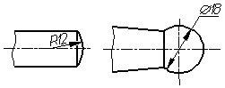
Figure 76 - Examples of applying the size of a spherical surface
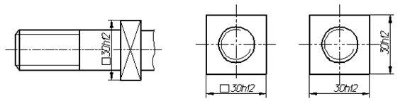
Figure 77 - Examples of applying size using the square sign
In front of the dimensional number characterizing the taper, the sign “” is applied, the acute angle of which should be directed towards the top of the cone (Figure 78).
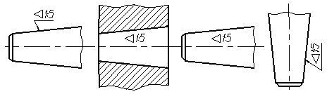
Figure 78 - Examples of designation of taper
The sign of the cone and the taper in the form of a ratio should be applied above the center line or on the shelf of the leader line.
where D is maximum diameter cone, d is the minimum diameter of the cone, H is the height.
The slope of the surface should be indicated directly at the image of the surface of the slope or on the shelf of the leader line in the form of a ratio, in percent or in ppm. In front of the dimension number determining the slope, the sign “\u003e” is applied, the acute angle of which should be directed towards the slope (Figure 79).
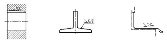
Figure 79 - Examples of grade designation
When applying the dimensions of the conical chamfers, the dimension line is drawn parallel to the axis of the cone. The dimensions of the chamfers at an angle of 45 ° are applied, as shown in Figure 80.

Figure 80 - Examples of the designation of chamfers at an angle of 45 0
The dimensions of the flat and conical chamfers at other angles indicate - linear and angular dimensions or two linear dimensions (Figure 81).
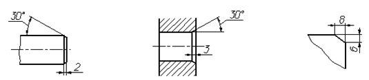
Figure 81 - Examples of the designation of chamfers at an angle other than 45 0


