Modern engineering survey methods. Garden relief plan
Design and coordination
- Preparation of dendroplanes and accounting lists (dendrological part of the project)
- Design of artificial relief elements (retaining walls, stairs, ramps)
- Projects (plans) of improvement, gardening of the territory
- Development of the SOD (traffic management project)
- Inspection of trees and shrubs in a given area
- The passport of improvement of the territory with entering data into the AIS "Register of green spaces"
- Passport on the object of flower decoration
- Conclusion of the Department of Nature Management and Environmental Protection of Moscow on design materials
Environmental regulation and support of enterprises
- Moscow waste inventory
- The list of measures for environmental protection (section PM environmental protection)
- Ecological payments (eco-payments)
- VAT (allowable discharge standards)
- Waste Management Reporting for SMEs
- Hazardous waste certification
- MPE (maximum permissible emissions)
- PNOOLR (draft standards for the generation of waste and limits for their disposal)
- 2-TP Statistical Reporting
- Technical Report on the Consistency of the Production Process
- The procedure for production control in the field of waste management
- Integrated environmental services for enterprises and the preparation of statistical reporting
- License for the collection, transportation, processing, recycling, disposal, disposal of waste of hazard classes I – IV
Plan of relief organization, vertical layout, geoplasty of artificial relief elements
Development of a plan for the organization of relief (vertical layout) - This is an engineering measure to artificially change, transform and improve the existing terrain by cutting or adding soil for use in urban planning purposes. The main purpose of the vertical layout is to create planned surfaces that meet the requirements of development and landscaping. The vertical layout of the territory is designed to create favorable conditions for the placement of buildings and structures, laying streets, driveways, underground utilities. The main tasks of the vertical layout include:
- organization of runoff of surface water (rain, rain and melt) from urban areas
- providing acceptable slopes of streets, squares and intersections for safe and convenient movement of all types of public transport and pedestrians
- creation of favorable conditions for the placement of buildings and the laying of underground engineering networks
- relief organization in the presence of unfavorable physical and geological processes (flooding of the territory, flooding with groundwater, ravine formation, etc.)
- giving the relief the greatest architectural expressiveness
- creation of artificial relief as necessary
- solving problems during the construction of large and unique plane structures (sports centers, airdromes, etc.).
The vertical planning project is being carried out simultaneously with the development of a planning solution for the territory. The composition of the vertical layout project depends on the complexity of the planning solution and the terrain, as well as on the required detail of the developed solutions. Drawings of the vertical layout project are among the drawings performed at the design stage. Drawings are made in the form of the most understandable and accessible for the manufacturers of work.
Developing a plan for the organization of relief, make up plan earth masses
- a project document defining the volumes of earth masses to be moved.
The ground mass plan is a drawing in the form of a grid of squares with a side of 5, 10 or 20 m, depending on the scale of the plan and the required
volume calculation accuracy earthworks. In the corners of each square sign design marks, marks of natural relief with
the corresponding sign of their differences, called working marks. According to the working elevations and squares (taking into account the excavations and embankments), the volume of earthwork is calculated.
The volume of earthworks at the facility are important indicators that determine the economic efficiency of the developed vertical design project. The calculation of the volume of earthwork is a prerequisite for determining the cost, the choice of methods and means of production, establishing the volume of soil for backfilling or removal of its surplus. Usually soil is transported from the nearest construction sites and it is used either to backfill pits or to arrange slides. Surplus soil during the construction of landscape architecture is usually formed by digging pits for ponds, buildings and structures. Such surpluses are used to fill hills, ramparts, etc. In principle, exporting surplus soil or importing it on the contrary is not profitable for production workers, or is it associated with high transportation costs. In some cases, when the necessary soils are not available nearby, it is necessary to provide for their transportation from quarries, and excess soils, especially if they are not suitable, are heavily littered or toxic, should be taken to a landfill. When developing vertical planning projects for landscaping objects, it is necessary to balance the volume of earthworks, in this case, the movement of earth masses is minimal and there are no transportation costs. In order to have an idea of \u200b\u200bthe location of embankments and excavations on the designed site, a cartogram of earthwork is compiled. It serves to determine the boundaries between the notches and embankments using the working marks of the vertices of the grid of squares, the values \u200b\u200bof which are recorded on the cartogram at each of its vertices. Using work marks, points of zero work are calculated and plotted, at which the projected plane and the earth surface intersect. They are located between adjacent points, the working marks of which have opposite signs.
Before embarking on the development of the site, it is necessary, as you probably yourself know, to draw up its master plan, dividing the site into functional zones and providing convenient entrances and approaches to them.
No less important is the so-called vertical layout of the site. To do this, you need to evaluate its topography and have appropriate geological data that should give an idea of \u200b\u200bthe type and nature of the soil, the depth of its freezing, the level of standing and the chemical composition of groundwater, etc. Such information can be obtained from local geological, architectural and construction organizations, but It is also worthwhile to ask those neighbors who laid the foundation, made a well, dug a cellar, or explored their own site, detaching several pits 2-3 m deep.
When organizing the relief, they must take into account the surrounding buildings - residential buildings, streets, utility sites and recreation places. Of course, storm and melt water, the main conductors of which are drainage channels and main pedestrian paths, should not get here from the site. In fig. 1 shows examples of the organization of the relief in areas of different locations.
Fig. 1. Examples of the organization of the relief of the site on the southern (a), eastern and western (b), northern (c) slopes and on a flat area (d):
1 - a platform for the house; 2 - platform under the barn; 3 - ditch
On the site located on the southern slope, there are horizontal platforms for a residential building and outbuildings, as shown in Fig. 1 a. The joints of the slopes of the residential building site with the southern and eastern slopes of the site are used for pedestrian paths, which will be storm drains. If the site is located on the eastern or western slope (Fig. 1, b), then in an elevated place they make a platform for a residential building, and in one of the lower places - for household buildings. In this case, slopes are sure to be arranged. The general nature of the slope is preserved. Drainage is laid in the aisle.
In the lower part of the plot there is a collection of storm and melt water that leads to a ditch of the driveway. When the site is located on the northern slope (Fig. 1, c), it is necessary to divide the entire territory into terraces - horizontal or with a slope to the west and east. Their number can be arbitrary. The slopes connecting the horizontal terraces are covered with turf or strengthen and used for berry planting or decorative planting. If drainage is needed, it is arranged on each terrace with access to lateral open ditches. At the intersection of pedestrian paths with slopes, it is best to make steps.
On a flat platform (Fig. 1, d), it is desirable to create an artificial relief with three slopes: southern, eastern (prevailing) and western (auxiliary). Slope slopes - not less than 0.04%. The relief is performed with soil taken from the sites for the construction of a residential building, farm buildings, for laying the main paths. Drainage can be of any design, but its depth should provide a drain of storm water into the ditch of the road.
Earthwork and planning work is performed simultaneously after the division of the site into zones. The boundaries of the zones, ridges, and intersections of the slopes are marked with sticks - with sticks. To determine the vertical marks, you can use an ordinary garden hose by inserting a glass tube at both ends. On the level of water make marks on the stakes, in accordance with which they are adding. Where its height is more than 30 cm, the soil layer is removed and separately stored, and soil is used for backfilling, taken out of trenches for foundations, drainage, paths, etc., pouring it with water and a trowel in layers (after 10-15 cm ) Then, fertile land is laid on top. Only the correct and thorough conduct of excavation and planning works allows you to create good conditions for the normal functioning of all objects and areas of the site.
The plan for the organization of the relief is an important document that should be available to anyone who has decided to modify the relief of their personal plot. Using this plan, you can make some adjustments to the terrain or completely change it for the better. There are a lot of options for landscaping in the garden, and the choice is only for the owner of the garden.
Relief plan
The development of a plan for the organization of the relief, the second name of which is vertical planning, is an engineering process for artificially making amendments and various effects to the existing relief of a site by adding soil to apply it to urban planning. Vertical layout is used to create a surface plan that will satisfy the needs of the builder and engineering beautification plot. This type of relief organization creates favorable conditions for placement of buildings, driving directions, underground engineering communications.
The relief plan consists of the following items:
- from the creation of a relief with runoff from the territory of liquids, for example, rain and other, from urban areas;
- to create a relief with the necessary slope of the site and other intersections to achieve the safe movement of any vehicles;
- drawing up effective conditions in order to place buildings and lay underground engineering networks;
- if there are poor physical and geological conditions, flooding of the site with groundwater and so on;
- relief plan with a more expressive architectural form;
- organization in some cases of artificial types of reliefs;
- solution of the problems encountered during the construction of large and unusual buildings.
A similar scheme is implemented along with the creation of a plan for solving the plot. The composition of such a project is based on the difficulty of planning decisions and terrain, as well as on the necessary details of the existing conditions. The drawing for the organization of the relief of the site in the country or in the park should be made as clear and accessible as possible. An example of such a drawing is shown in the photo below. At the same time, as you can see, such a drawing includes all the smallest details.

Infield Plan
When creating a plan of earth masses, various important points are taken into account. At the same time, it is a project document that determines the volume of earth masses required for subsequent movement. The earthwork plan is a drawing in the form of a grid of squares. Such a plan can only be drawn up by a person competent in this matter, since otherwise it is impossible to correct the terrain on the basis of it, but, on the contrary, it can be spoiled even worse.
The volume of earthworks at the facilities are paramount data that determine the developed estimates in vertical planning from an economic point of view. The calculation of earthwork is a prerequisite for determining the price, choosing a method and materials for carrying out the work, identifying the volume of soil for adding or removing its excess mass. Soil is transported mainly from the nearest construction sites and it is used either to fill the recesses into the lard, or to equip the slides in the garden or park in the city. Excess soil during the construction of various architectural objects remains mainly through the accumulation of pits under the pond or any other structures. Such unnecessary soil is used for filling hills, shafts and much more.
Relief alignment
Basically, huge masses of soil are taken out with the help of special construction vehicles, or, otherwise, it is not advisable for builders, or this becomes the reason for the high cost of transport rental for these tasks. In some ways, when the right soil is not nearby, it will be necessary to order its transportation from quarries, and excess soil, in particular if it is unsuitable, very littered or toxic, is transported to garbage. When creating a project for organizing the relief of landscaping facilities, it will be necessary to balance the amount of work on the ground, in this case, the transportation of soil mass is minimized and there is no cost of renting vehicles.
To represent the location in the projected areas under the embankment of soil, a cartogram is created for further taskson a plot of land, in a park or in a garden. It is intended to determine the boundary between the notches and embankments by means of the working marks of the vertices of the square meshes. Applying data for work, indicate the points of work where the designed planes intersect and the surface of the earth. They are between adjacent types of points, while they have different signs.
Vertical layout
Vertical layout is a set of measures that are aimed at amending the terrain to create a surface that meets the necessary requirements. You can see an example in the photo below.
The main goals of the vertical layout are:
- Utilitarian:
- to organize the relief and runoff of water;
- to ensure comfortable movement of vehicles;
- creating effective conditions for valuable plant varieties to grow — trees, shrubs, and grassy associations;
- prevention of soil erosion.
- Aesthetic:
- giving the relief a beautiful expressiveness of architecture;
- arrangement of decorative construction on a light relief of stairs, retaining walls, and so on.
In order to solve any problems, a plan for the vertical layout of the landscape architecture object is drawn up. The plan for this option should be implemented with the creation of planning decisions of the site. The preparation of such a plan proceeds from the difficulty of planning decisions, as well as from the necessary detail in the implementation of the work. This scheme of a summer cottage or any other territory is made during design. They should be as accurate as possible. Consider what the vertical layout of the site consists of. It consists of design elevations and the movement of earth masses according to the statement.

Flat terrain
Vertical Layout Examples
Consider the most common and popular examples of a plan for organizing relief:
The first example of the vertical layout of the site
This type needs careful alignment of the given slopes throughout the garden, for any sections, paving paths, flower beds and so on. The side of these slopes is one diagram surface drains. At the same time, such an example of the site makes it possible to drain the liquid. If just one organization of the surface of the site for wastewater is not enough, then together with the vertical planning plan, it is necessary to create a draft drainage and drainage system.
The second example is the emphasis on the natural topography of the site with retaining walls.
The second example of the vertical layout of the territory in your summer cottage or somewhere else consists of creating large-sized relief forms like terraces or pools. In this example, an important point is to preserve all the contours of the object, the total depth and microrelief of the site.
Vertical layout is carried out mainly in several stages:
- draft layout of the territory;
- the creation of the main forms;
- initial alignment of the site;
- formation of the necessary slopes;
- the very last stage is the creation of fertile layers, this stage is carried out before laying the lawn cover.
Each of these examples requires a special approach to the organization of work and the accounting of materials for its creation. For example, the first example is not as costly as the second, where it is necessary to deliver large masses of soil to the site. Each option has its undeniable advantages over other options for arranging the territory on a summer cottage. As you can see, these are just a couple of examples with which you can equip your summer cottage.
An important point: keep in mind that each type of earthwork requires high costs both from a material point of view and from a labor one. In order to correctly carry out the calculations of the required number of materials and fruitfully create the layout of the territory, we need a project for the relief of the site. Based on the difficult conditions on your homestead and the project, you can create a solution for changing terrain with varying degrees of effectiveness.
Park plan
One of the most important ways to carry out work on the ground is the correct choice of zero elevation marks, which determine the upper parts of the territory. In most moments, we see cases where construction elevationsnot consistent with the available soil on country territoryor any other place, for example, in a city park you can see such a picture. This becomes the reason for the formation of additional terrain drops on the territory and complicates the possibility of forming a flat territory for organizing leisure. Moreover, with the need for arrangement of drainage, its configuration becomes much more complicated. Moreover, such a zero position for all sections does not need to choose the same one. Otherwise, you will have the appearance of a house “planted” above other buildings of the territory on the plot, and then you will need to import large volumes fertile soilor "deepen the territory", and then it will be necessary to export a huge amount of soil outside the country. That is, your financial costs for the arrangement of a summer cottage will greatly increase.
Progress in the field of measurement technology, improvement of measurement methods and the results of their processing, the widespread use of computers for computational and graphic operations could not affect the technology of all kinds engineering surveys. For example, in engineering geology, along with the traditional methods of soil research: by drilling or exploration drilling, dynamic and statistical sounding, geophysical methods of electrical and seismic exploration are used.
In hydrometeorological surveys, aerospace survey methods are widely used from various types of carriers, including artificial satellites and space stations. During channel surveys and surveys of marine waters, radio-technical measuring instruments and various types of echo sounders are used.
Light-range finders, electronic theodolites, electronic tacheometers, satellite receivers are successfully being introduced into the practice of engineering and geodetic surveys. Processing of measurement results is mainly carried out on a computer. The graphic image of the terrain based on topographic surveys changes to a mathematical representation in the form of a digital terrain model (DTM) and terrain (DEM). Programs have been developed for the computer-aided design system (CAD) of linear structures, master plans based on DTM, etc. Based on the DTM, the volumes of reservoirs and earth masses are also calculated. The digital terrain model does not exclude the receipt with the help of various kinds of plotters and graphic images.
Along with the widespread use of ground and airborne methods in the study of surface and natural resources Earth for research purposes applies information obtained from space. With the help of satellite imagery materials, many practical problems can be solved. High-resolution spectrozonal images can be used to take measures to protect the natural landscape and waters from pollution. Space imagery is also used for the needs of cartography, expanding and deepening information about such long objects as main roads, pipelines, channels, when designing objects that occupy large areas.
DRAWING UP A RELIEF ORGANIZATION PLAN
With the help of the relief organization plan, the tasks of transforming the relief of the urban territory to adapt it to development, improvement and engineering and transport needs are solved. The organization of the relief provides a high-altitude solution of squares, streets, driveways; placement of buildings, structures and underground utilities; the possibility of storm water runoff and sewage.
The defining document of the project is the relief organization scheme (Fig. 2), drawn up on a topographic plan in the scale of 1: 5000 or 1: 2000.
Design decisions on the organization of the relief are given on the diagram mainly along the axes of the designed driveways in the form of design marks of the points of intersection of the axes and bends of the longitudinal profile. The diagram also shows the distance between the intersection points of the axes and the inflections of the profile, slopes in ppm and the direction of water flow. The scheme is attached to the projects of transverse street profiles (Fig. 3) on a scale of 1: 100 - 1: 200.
The approved relief organization scheme is mandatory for all departments and institutions involved in the development and development of urban areas.
The work plan for the organization of the relief is compiled on a topographic plan at the scales of 1: 500 - 1: 1000. Initial are the design elevations of the relief organization scheme.
The design relief formed by separate forming planes can be specified either in the form of profiles or design horizontals in combination with design marks.
In the profile-based method, a topographic plan is drawn with a grid along the lines of which are longitudinal profiles on the scale of the project plan. The distance between the profiles when planning the quarters is assumed to be 20-50 m, and when planning large areas - 100-200 m. The method of profiles is laborious and therefore rarely used.
Fig. 2. Scheme of relief organization
The method of design contour lines consists in the fact that the design contours of the relief formed after changing the natural relief by cuts and additions are drawn on the plan. Design horizontals between the lines of the folds of the slopes are represented by straight parallel lines equally spaced from each other. Section pfor project horizontals within 0.1 - 0.5 m, they are selected depending on the nature of the natural topography.
For plans of scale 1: 500 with a relatively calm relief, a cross section of 0.1 m is most often used.
The position of the design contours on the plan is determined by the design elevations of the points of intersection of the drive axes and the inflection points of the design relief. Distance l (laying) between adjacent project horizontals on the plan is calculated by the formula
where i -longitudinal design slope; M - denominator of the numerical scale of the plan.
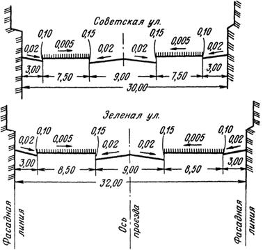
Fig. 3. Cross street profiles
At the border of two forming planes, the design horizons have a kink.
Planning for the organization of the relief begins with the streets. Initially, horizontal lines are designed along the passage, and then they are developed to the front line of the building. In this case, take into account the transverse slopes of driveways, lawns and sidewalks, as well as the height of the curb stones.

Fig. 4. A fragment of the plan for the organization of relief
When designing the relief in the intra-quarter territories, the initial ones are the design marks of the vertical layout along the streets. The vertical layout of intra-quarter driveways and pedestrian walkways should ensure the collection and removal of surface water from the quarter to adjacent street driveways or to a special drainage network. Design horizons in the intra-quarter territory are carried out taking into account the nature of the natural relief, providing for the smallest amount of earthwork. Steep slopes or elevated places are decorated with green slopes, retaining walls, ramps, stairs.
On the plan of organization of the relief indicate the marks of "clean floor" of the first floor, design and existing elevations of the corners of buildings and structures (Fig. 4).
MAKING A PLAN OF LAND MASSES
Developing a plan for the organization of the terrain, they draw up a plan of earth masses - a project document that determines the volumes of earth masses to be moved.
The earth mass plan is a drawing (Fig. 5) in the form of a grid of squares with a side of 5, 10 or 20 m, depending on the scale of the plan and the required accuracy of calculating the volume of earthwork. In the corners of each square sign design marks, marks of natural relief with the corresponding sign of their difference, called working marks. According to the working elevations and squares (taking into account the excavations and embankments), the volume of earthwork is calculated.
Between the corners of squares with working marks of different signs, as a rule, the points of zero work are searched by interpolation “by eye”. Connecting the points of zero work, build a line of zero work. In some cases, the plan of earth masses is illustrated by lines of equal marks of embankments and excavations drawn over its entire area.
Different types of squares are distinguished depending on the location of the line of zero work: homogeneous, when the signs of the working marks coincide for all corners of the squares (there are no points of zero work on the sides of the square), and either a mound or a notch must be made across the whole square; heterogeneous, when the signs of the working marks at different vertices do not coincide and the square is divided by the line of zero work into the sections of the excavation and embankment.

Fig. 5. Earth mass plan with a balance table
For a single homogeneous square, the volume of earth masses Vcan be defined as the volume of a prism having a base area R,equal to the square area, and the height equal to the arithmetic average of the working marks hall four corners
![]() . (2)
. (2)
The volumes of earth masses in inhomogeneous squares are determined after dividing them by a line of zero works and auxiliary lines into separate figures - rectangular triangles, rectangles, trapezoids, etc. The same order is accepted for incomplete squares. Scope of work V iin individual figures calculated by the formula
where P i -area of \u200b\u200ban individual figure; h cf - the average working mark of this figure.
The calculated volumes in cubic meters for each square are written out with the corresponding sign in the table of earth masses. The total volume is signed at the bottom of the drawing (Fig. 5).
With sharply rugged terrain, the vertical profile method is used to calculate the volume of earth masses. For this purpose they also use the earthworks plan.
Having determined the total volumes of the excavations and embankments, they balance the earth masses, i.e., they determine whether the excavations and embankments compensate each other. In practice, it is preferable that the volume of excavations slightly exceed the volume of embankments, since it is easier to remove excess soil than to find reserve soil for the embankment.


