Earthwork volume formula. Earthworks cartogram
Instruction manual
The initial data for the KZR is the geo-base and the vertical layout of the territory. Geopods should indicate existing elevations. Usually they are indicated as separate points or contours. A vertical plan drawing shows the design ground level.
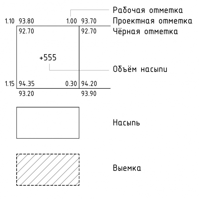
It is necessary to apply a grid of squares with a side of 10 m or more, depending on accuracy. In each corner of the square, you need to enter black (existing) and red (design) marks, as well as working marks representing the difference between red and black. Obviously, the angles of the squares may not coincide with the known elevations, in which case they are calculated by interpolation.
Positive working marks indicate the embankment and are marked with a “+” sign, negative ones indicate a notch and are marked with a “-” sign. If there are plus and minus working marks on the side of the square, then zero points are calculated between them (also by interpolation). Connecting these points, draw a line of zero work, that is, the boundary between the notch and the embankment.
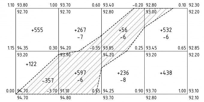
Next, the volumes of the excavation and embankment for each square are calculated. You need to multiply the average working mark by the square area. For example, if in the corners of the square marks were obtained: 1.10, 1.00, 1.15 and 0.30, and the side of the square was 25 m, then the volume of the embankment would be: ((1.10 + 1.00 + 1.15 + 0.30) / 4) * (25 * 25) \u003d 555 (m3).
If the square is divided by a line of zero work, then to calculate the volume, you may need the formula for the area of \u200b\u200ba triangle or trapezoid.
As a result, the volumes of the notches and embankments of all squares are added up and the total volume of embankments and notches is obtained. Comparing these volumes, teach the balance earth masses.
Reporting is an important step in the work of any company or individual entrepreneur, even if the activity is temporarily suspended. Indeed, in this case, no one canceled the timely submission of reports. If the time has come when no economic activity is being conducted, and if there are no movements in the accounts, then it is time to prepare a zero balance.

You will need
- - balance sheet;
- - tax reporting;
- - statistical reporting.
Instruction manual
An entrepreneur is obliged to submit a tax balance declaration to the tax authorities within the time limits established by law. Most often, a non-working company does without a staff and does not even have an accountant, in this regard, some entrepreneurs believe that it is not necessary to report to anyone. However, if an individual entrepreneur or organization does not deliver on time zero reporting, then the tax authorities impose administrative sanctions.
Zero balance consists of the balance sheet, statistical and tax reporting. If you submit the necessary paper in a timely manner, then the organization is exempt from paying property tax and profit. A standard tax return, income statement, and generally accepted accounting statements should be prepared.
For those who have chosen a simplified taxation system, the provision of accounting reports is not required; accordingly, when preparing a zero balance, it is not necessary to demonstrate the accounting result.
In the zero balance, all fields must be zero, with the exception of statements about the organization. Signs of zero activity are the lack of turnover at the bank and cash desk, the absence of accruals on wages, and the absence of any other expenses. All data are entered into the asset and liability and are indicated in thousands of rubles.
The zero balance reflects the same information on the authorized capital that is indicated in the balance sheet. The assets reflect the organization’s resources, and the liabilities reflect the amount of the authorized capital. If the authorized fund is formed from cash, this should be reflected as receivables. As a result, we can conclude that the zero balance is the same
The second row of the head of the table is provided for the name of the territory for which the data is presented. For example - “Factory Territory”, “Pre-factory Territory”, “Residential Development” (in our case, “Site No. 1” and “Site No. 2”). The number of allocated parts of the territory is specified according to design data. The procedure for counting different names of territories is the same.
Consider the example of filling the sheet of volumes of earth masses for the case of vertical planning before the construction of buildings and structures.
|
Name of soil |
Quantity, m3 |
||||
|
Plot number 1 |
Plot number 2 |
||||
| 1. Ground layout of the territory * | |||||
| 2. Displaced soil, incl. on device: | |||||
| a) underground parts of buildings (structures) | |||||
| b) road coverings | |||||
| c) railway tracks | |||||
| d) underground networks | |||||
| e) drainage facilities | |||||
| f) fertile soil in landscaping areas | |||||
| 3. Ground for the device subgrade | |||||
| highways | |||||
| 4. Soil for the device of a subgrade | |||||
| railway tracks | |||||
| 5. Soil for the device of high floors of buildings and | |||||
| debris | |||||
| 6. Compensation correction | |||||
| (residual loosening) | |||||
| 7. Losses during transportation | |||||
|
Total suitable soil: |
|||||
| 8. The lack (excess) of suitable soil | |||||
| 9. Unsuitable soil | |||||
| grounds of buildings (structures) subject | |||||
| removal from the territory | |||||
| 10. Fertile soil, total, including: | |||||
| a) used for landscaping | |||||
| b) lack (excess) of fertile soil | |||||
| 11. Total processed soil | |||||
* Subject to preliminary cutting of fertile soil.
The procedure for filling the sheet of volumes of earth masses:
1. In line 1 we enter the volume of the embankment (A) and excavation (B) of the soil of the territory planning. We take volumes from the plan of earth masses (total volumes of the embankment and excavation throughout the entire planned territory).
2. In line 2, we consider extruded soil (B), which is calculated as the sum of the lines (B 1, B 2, B 3, B 4, B 5, B 6), including:
a) Data on the volume of excavation (B 1) from the device of the underground parts of buildings (structures) we take from the documentation of the KZh brand.
b) The volume of excavation (V 2) from the device of road coatings is calculated as the product of the coating area by the thickness of the structure of this coating. For each type of coverage, the excavation volume is calculated separately, the sum of all types of coverage of the designed area is entered in the table.
c) We take the data of the volume of excavation (B 3) from the device of the railway tracks from the documentation of the ПЖ brand.
d) We take the data of the volume of excavation (B 4) from the device of underground networks from the corresponding mark of documentation (VK, NV, NK, etc.), where this network is presented.
e) Data on the volume of excavation (B 5) from the device of drainage facilities, we take from the drawings, where they are presented.
f) The volume of excavation (B 6) from the arrangement of fertile soil in the landscaping areas is calculated as the product of the landscaping area and the thickness of the fertile layer.
B \u003d B 1 + B 2 + B 3 + B 4 + B 5 + B 6
3. In line 3 we enter the volume of the embankment (G) and excavation (D) of the soil from the device of the subgrade of roads. We take these volumes from the documentation of the AD brand.
4. In line 4 we enter the volume of embankment (E) and excavation (G) of soil from the device of the subgrade of railway tracks. We take these volumes from the documentation of the brand ПЖ.
5. In line 5 we enter the volume (3) of soil from the device of high floors of buildings and debris of structures. We take these volumes from the corresponding mark of documentation (TX, AR, etc.), where this information is presented.
6. In line 6, we calculate the correction for the seal (I). The value of the compaction coefficient (X) is taken according to the table. 14 and geotechnical surveys.
And \u003d X * (A + G + E + 3)
7. In line 7 we calculate the loss (K) during transportation of soil. The value of the loss coefficient (U) during soil transportation is taken in accordance with paragraphs 4.22 -4.43.
K \u003d Y * (A + G + E + 3)
8. In the line “Total suitable soil” we calculate the volume of suitable soil of the embankment (L) and excavation (M):
L \u003d A + G + E + 3 + I + K
M \u003d B + C + D + F
9. In line 8 we calculate the deficiency (excess) of suitable soil (N). The value is calculated as the difference between the volume of the embankment (L) and the recess (M). We take the value modulo and enter in the column a lower value of the embankment (L) or excavation (M). If L\u003e M, then in the column of the name of the soil indicate "Lack of suitable soil." If L< M, то в столбце наименования грунта указываем «Избыток пригодного грунта».
H \u003d | L - M |
10. In line 9 we enter the amount of soil (O) to be removed (fertile soil layer, peat, soil, unsuitable as the base of buildings, structures). The volume value is taken from the soil removal plan, which is drawn up similarly to the earth mass plan. This value (O) is entered in both columns of the table of the embankment and excavation.
11. In line 10, in the excavation column, fill the volume of fertile soil (P) removed before earthworks within the boundary (line) of zero work. The value is calculated as the product of the area of \u200b\u200bthe removed plant layer by the thickness of the fertile layer. We take the rate of removal of the fertile layer from the engineering-geological report.
12. In line 10a we enter the value of soil (B 6) used for landscaping from line 2e.
13. In line 10b, we consider the deficiency (excess) of fertile soil (P). The value is calculated as the difference between the volume of the entire fertile soil (P) and the fertile soil used for landscaping (B 6). The value is taken modulo and entered in the column of a lower value (P) or (B 6). If P\u003e B 6, then in the column of soil name indicate "Excessive fertile soil." If P< В 6 , то в столбце наименования грунта указываем «Недостаток плодородного грунта».
P \u003d | P - B 6 |
14. In line 11 we consider the volume of the processed soil of the embankment (C) and excavation (T):
C \u003d L + H + O + B 6 + P
T \u003d M + H + O + P + P
The volume of the processed embankment soil (C) is calculated as the sum of the values \u200b\u200bonly from the embankment column.
The volume of digging soil to be processed (T) is calculated as the sum of the values \u200b\u200bonly from the excavation column.
If the values \u200b\u200bof C and T are equal, then the balance sheet of the volumes of earth masses is performed, therefore, the sheet is filled correctly.
The plan for the organization of the relief (vertical layout) is carried out on the basis of the layout plan without specifying and applying the coordination axes of the buildings, coordinates, sizes and dimensional references, direction indicator to the north.
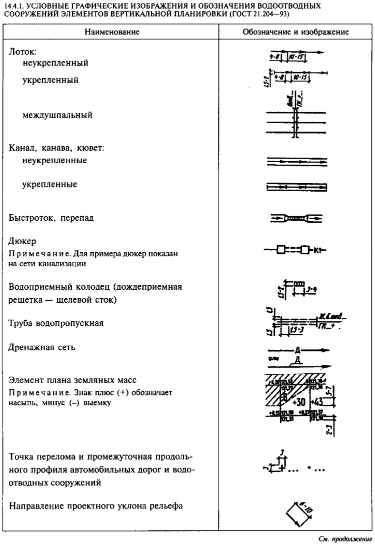
The plan for the organization of the relief (vertical layout) is carried out in accordance with GOST 21.508-93, it must provide for a normal drainage from the construction site, safety and favorable traffic conditions on the roads, taking into account the features of the existing relief. Conditional graphic images and symbols are given in table. 14.4.1.
The plan for the organization of the relief should provide for the implementation of a minimum amount of earthwork during the construction of buildings, highways etc.
On it, the horizontals of the natural relief are drawn through the contours of the designed buildings, but they do not show the elements of landscaping and landscaping. The design (red) marks of the layout and the actual (black) marks of the terrain on the top of the blind area at the intersection of its outer edges with the relief or, in the absence of a blind area, at the intersection of the faces of the walls with the relief, are also indicated here. Marks are indicated in the corners of buildings in the form of a fraction - design (red) in the numerator, and the actual elevation mark (black) in the denominator. In addition, other necessary marks and data are provided.
The plan for the organization of the relief should, as a rule, be carried out in the design horizontals (see Fig. 14.4,2),
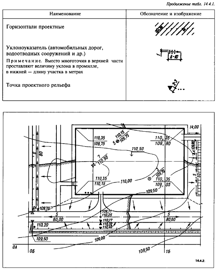
In this case, the horizontal line is carried out with a relief cross section through 0.1 and 0.2 m throughout the entire planned territory. It is allowed to apply project horizontals with a cross-section of the relief in 0.5 m in areas with a uniform slope.The marks of the design contours are indicated on the elevation side of the relief, while the design horizons that are multiples of 1 m are indicated completely, and for intermediate ones only two decimal places are given.
When implementing the plan for organizing the relief, the angles of buildings, structures and platforms, the intersection of the axes of roads, etc., are usually taken as reference points for planning, in this case, the direction of the slope of the design relief is indicated by arrows (Fig. 14.4.2).
Raised and lowered points of the design relief are indicated with a special sign. Next to the sign indicate the numerical value of the mark.
A plan of earth masses is compiled to calculate the volume of earthwork according to the plan for the organization of the relief (vertical layout). The area of \u200b\u200bthe site is divided into squares with sides equal to 20 m. The squares fit into the construction geodetic grid. It is allowed to snap squares to the “red” line or to the center basis. You can apply a grid of squares with sides of 10, 25, 40 and 50 m, depending on the nature of the relief and the required accuracy of calculation (Fig. 14.4.3).
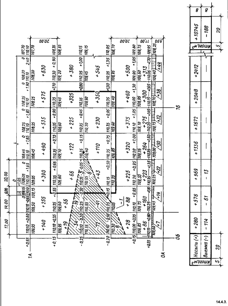
A special table is placed under each column of squares of the earth mass plan, the width of the graph of which corresponds to the grid of squares (see Fig. 14.4.3.). In this table, the total volumes of the embankment and excavation along the column of squares are indicated, and on the right, the total volumes of the embankment and excavation throughout the planned territory.
Geodetic calculations in vertical layout
Vertical layouta set of works on the conversion of natural relief to design in geodesy.
The structure of the vertical layout includes a plan for the organization of the relief and a plan of earth masses in construction.
2.1. Planning a relief organization
The basis for the development of the plan for the organization of the relief are topographic plans on a scale of 1: 500 - 1: 5000, compiled according to the results of leveling construction sites in squares.
The design relief formed by the individual forming planes is defined by the design horizontals in combination with design marks. The design contour method consists in straightening out horizontal contours on a topographic plan in accordance with technical requirements layout. Using them, they make a surface layout diagram, determine the marks of reference points, the direction and slope of the slopes. The design horizontals between the lines of the folds of the slopes are represented by straight parallel lines equally spaced from each other (Fig. 1). Section h for project horizontals within 0.1-0.5 m, they are selected depending on the nature of the natural topography. The position of the design contours on the plan is determined by the design elevations of the points of intersection of the drive axes and the inflection points of the design relief. Distance d (laying) between adjacent design horizons on the industrial and civil construction plan
Fig. 1. Construction of design contours on a fragment of the road
At the border of two forming planes, the design horizons have a kink (Fig. 1).
At certain design elevations, horizontals are drawn inside the quarter, taking into account the possibility of water drainage on the inside roads towards the streets. At the same time, the smallest amount of earthwork and an equal ratio between the volume of excavation and its filling are provided.
The transition of the design relief to natural is carried out using slopes. Their steepness (the ratio of the height of the slope to the width of the base) is taken depending on the mechanical composition of the soil and the design purpose of the slopes. So, in Fig. 2 the steepness of the slope is adopted 1:10 and base width 10h 1 .For example, workingthe mark of one of its peaks is 0.19 m, which is 1.9 m in the scale of the plan 1: 1000. Slopes are depicted in accordance with conventions, as "planned slopes", with short and long strokes through 2 mm and directed fromedge of the slope to its sole.
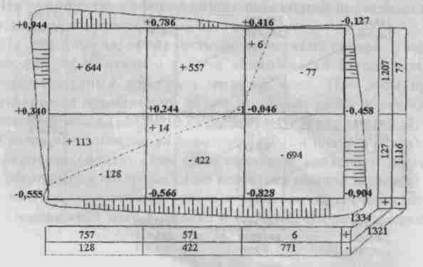
2.2. Earth mass planning
The ground mass plan is a drawing (Fig. 3) in the form of a grid of squares with a side of 20 or 40 m, depending on the scale of the plan. Work marks are signed in the corner of each square. By workers marks and squares (taking into account excavations and embankments) underread volumes of earth masses.
|


