Pavement regeneration. Technology of hot, warm and cold regeneration. Used machinery and equipment. Advantages and disadvantages. Advantages of using “ANT” cold recycling technology
Typically, there are several options available to repair a damaged road, and it is often difficult to determine which is the best. However, the answer to two important questions is designed to help determine which option is optimal according to the cost / effectiveness criterion:
- What is integral to existing pavement?
Utilization of flexible sidewalks. One of the reasons for the disposal of waste. That the recycling of asphalt agglomerate is the reuse of milling, which comes from layers of the road that are already in operation. In this case, the exploitation of quarries for the extraction of aggregates and the use of bituminous products.
At that time, the National Institute of Roads specifications were established, which, in turn, require higher quality materials that make up the lower layers of the sidewalk. Recycling reuses existing asphalt and aggregate on the road. It is being replaced by a safe one.
A quick inspection to visually assess the condition of the road in combination with some basic tests (e.g. deviation measurement) is usually sufficient to assess the fracture mechanism. It is important to determine if damage is limited to the trailing layer (or top layers pavement) or damaged pavement construction;
Reduces costs due to the use of new materials and transportation costs. exhausted. Bulges. troughs are adjusted with recirculation. Cracks in the sidewalk removed. Deformations, such as fingerprints. anticipating a reflection of a future crack. Large piles of material obtained from old sidewalks.
When carrying out work on cold recycling
On-site disposal minimizes the closing time of the strip for reconstruction. Recycled pavement can be recycled as soon as its useful life has ended. Recycled pavement may be of higher quality than the original. Any asphalt can be recycled to solve existing problems with lower cost and greater benefits over its useful life. A sidewalk that has reached the end of its design phase and shows signs of cracking and fatigue.
- What does the road owner really want?
Is, for example, a 15-year estimated life expectancy of the road, or are there lower capital costs, only to maintain the existing rate of deterioration and maintain the required quality of pavement for a further, say, five years?
These issues have one single purpose: determining the most cost-effective solution to a particular problem within the framework of the project requirements.
There are drainage problems in the road surface. There are grounds with the base of the sidewalk. The pavement, which is cracking and its degree of wear, has led to the formation of potholes. In rural areas, waste recycling projects are being successfully implemented. Congested intersections in cities and national roads. In the draft sidewalk project. Design should be based on a specific situation.
Recycling is not a panacea. Disposal of any route always requires a preliminary study. It does not solve the problems associated with the quality of materials in the deeper layers. since it does not solve the problems associated with the structure of the road. Cold mixtures require cold recycled mixtures, which require a ripening or curing period of the mixture.
Surface restoration
Surface restoration is limited to the upper layers of pavement to a depth of 100 mm. Damage here is usually associated with bitumen aging and cracking, which starts from the surface under the influence of heat.
- Laying thin (about 40 mm) layer of hot asphalt over a damaged surface. This is the easiest way to surface repair. For the preparation of asphalt, modified binders are often used to increase the service life of the end layer. However, repeated deposition of the wear layer over the existing one increases the height. roadbed and can cause problems with passage through it and drainage.
Asphalt content. quality and gradation of units and available technologies. physical properties of extracted asphalt. Hot processed plant. Full restoration of thickness. Hot processing in place. This is a special technology that allows you to reuse or reuse original building materials.
These materials are formed when removing asphalt pavements for reconstruction. Including with the introduction of a small amount of primary materials. Utilization of flexible sidewalks. with or without rejuvenation. Asphalt surface is restored at depths greater than. It may or may not include the underlying material.
- Shredding Damaged layer and its replacement. Using this method, a damaged asphalt concrete layer is removed and replaced with a layer of new hot asphalt mix, often with a modified binder. This method is relatively fast due to the high performance of modern road milling machines. Destruction is removed along with the asphalt layer, and the height of the road is preserved. But at the same time there are expenses for transportation and disposal of the remote layer.
On-site recovery with highly penetrated asphalt cements also takes place. hydrated lime and mixtures of lime and fly ash. Material can also be obtained from the sidewalk using cold milling. Restore the indicated estimates and eliminate the deficiencies. providing a new longitudinal-transverse profile of the existing asphalt pavement. This allows you to solve a variety of problems. as previously stated.
Quality control of work preparation agb-mixture
Installation for cold waste recycling. Disposal of flexible floors Ambulatory plant for cold recycling Regular installation sequence for the environment. Dosage Both the emulsion and the pre-treatment water are accurate and automatically arrive at the recycled square meter. Recycling asphalt pavement and parts of an existing base stabilized by an asphalt emulsion. These devices also have metering devices for binders. Cementing, or both.
- Recycling with the addition of a bitumen emulsion to the material of the existing pavement (recycling to a shallow depth). New, cold material is prepared from the crushed material of old clothes in a regenerator-mixer at the place of work. This type of recycling aims to introduce fresh bitumen emulsion into existing asphalt concrete. In addition, the quality of the final asphalt mix was purposefully changed by the addition of an emulsion.
The recycle product must be protected by sealing or with thin layers of cold mixtures. depending on the quality of existing materials. The materials of the asphalt layers are in high proportion in the material to be recycled. It is also called full depth restoration. processed or not using hydraulic cements.
It does not include a granular base layer. This improves the structure and allows the placement of surface treatments or asphalt mix in hot or cold condition. Its main application is to improve the structural capabilities of the road. Very used on secondary roads. after curing it.
Strengthening Pavement
Repairing pavement damage is usually done as a long-term solution. Sealing granular material is actually an improvement, since the higher the density of the material, the better its strength characteristics.
- Complete reconstruction. This is an option when restoration is combined with reconstruction. Essentially, reconstruction involves re-building the road. Where traffic flows are large, it is sometimes more advisable to build a new road along a separate highway.
Disposal of flexible sidewalks The benefits of disposal as a conservation method The disposal of asphalt pavements means, first of all, the use of resources available on site. Eliminates the need to find quarries and landfills near the job site and improve work. Benefits of disposal as a conservation method. recycling reduces the demand for materials such as aggregates and asphalt. starting from new to the place of work. Benefits of disposal as a conservation method Conservation of natural resources.
More respect for the environment. Changes can be made in vertical and horizontal alignment without the need for basic actions. Entrance to tunnels or passage of bridges prevents the growth of the existing level on the road. Recycling Flexible Floors Technical Benefits of Recycling Recycling avoids calibration problems. which would be harder to do with classical methods.
- Application of additional layers (from granular material and / or asphalt) over an existing surface. Thick, laid on top layers of asphalt concrete are often the easiest solution to problems with paving under heavy loads. However, increasing the height of the road often requires separate drainage and creates problems with road traffic.
Since a transport company can be opened within a few hours. Structural failures can be restored without discarding existing materials. Road occupation time is shorter than with conventional methods. Recycling flexible floors Technical advantages of recycling The impact of traffic is lower. Conventional methods require the intervention of all lanes. because they exceed these bands, where the lightest traffic passes. If the track has surface deterioration. Optimization of available resources. Recycling allows you to rehabilitate only the lane that needs it.
- Recycling to great depths, to the entire depth of the damaged pavement, thus creating a new thick homogeneous layer with higher strength characteristics. Additional layers can be laid on top of the recycled layer where the pavement needs to be substantially modernized. Stabilizers are added to the recycled material (bitumen emulsion, with necessary - high strength crushed stone), especially where the material of the existing pavement is of insufficient quality and requires strengthening. The task of recycling is to maximize the restoration of existing pavement. In addition to reusing the upper layers of the existing pavement, material below the recycling level remains intact.
Disposal may solve the problem automatically. Utilization of flexible sidewalks of a technical nature. The road structure consists of different layers, the purpose of which is to transfer traffic requirements that reach the primer level. which has a low bearing capacity. which gives a certain quantitative mechanical behavior through the modulus of elasticity.
Over time, the rearrangement of particles occurs, which leads to deformations on the surface. charge transfer is carried out through the mineral skeleton of the layer. Determine the type of subheading that you have. - Identify the type of failure that occurred. When we are faced with rehabilitation, it is important to consider: -Identify each of the layers of the structure and its nature. Disposal of flexible sidewalks of a technical nature Faults arising from the foundations of the company.
Cold recycling method
Constantly increasing traffic on public roads, as well as doubling the axle loads, requires an increase in the bearing capacity of existing road pavement.
Currently in the area road construction along with traditional methods of repair, reconstruction and strengthening of roads, fundamentally new technologies have appeared that meet the latest requirements of increasing intensity trafficbased on the latest advances in science and technology.
Especially regarding heavy loads or traffic. Thermal cycles and solar radiation lead to aging and progressive wear of the layer. Etc. What will affect the availability of new units. Environmental conditions. air emissions. This can have a devastating effect on the road.
All offers that include the recycling process are cheaper. In some cases, economic comparison is clearly not favorable for the processing process in the strict sense. Utilization of flexible sidewalks of an economic nature. This is the last block. This is one that has a more specific weight when deciding between one decision and another. Design Methodology for Recycling pavement.
One of such technologies that most fully meets the requirements for reconstruction, repair and operating conditions of roads is the “Method cold regeneration"(Recycling).
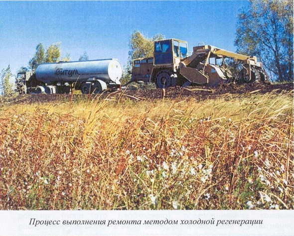
This method of repairing coatings is modern, well-established in road organizations, a method and one of a kind, because it provides restoration of the foundation of pavement in a way that allows the reuse of the old coating material. The use of this method allows to reduce the time of reconstruction, repair, significantly reduce costs. Cold regeneration works are carried out without stopping the movement.
The methodology for designing flexible processing equipment for the recycling of pavements - The possible contribution of materials - The budget for the work and the subsequent maintenance of the road - The current behavior of the sidewalk - The layer or layers to be processed - Availability of materials and equipment - the period in which the work will be applied.
Ministry of Transport of the Russian Federation
Localized structural and generalized structures. with asphalt already dry. Visual inspection Visual inspection shall be carried out by experts and. where possible. A flexible design technique for recycling pavement for pavement processing after a long period of rain.
The method of cold regeneration (recycling) is the strengthening (stabilization) of soils, stone materials and asphalt granulate binders by pre-milling and mixing on the road. This achieves significant material savings. In addition, the destruction of the old coating allows you to eliminate the source of the occurrence of new reflected cracks. No disposal of old coating is required.
Places with significant deterioration. Disposal of flexible walkways that may require special treatment. Visual inspection Define sections that show similar types and levels of wear. -We must require surface regularization. -We have a repair. -Characterization and condition of the Berms.
Visual inspection - tracking the track and terrain. - Areas where you can park construction equipment. - Problems associated with drainage. -Problems related to borders, hatches, prefabricated work, structures and access. Design Methodology for Pavement Recycling Auscultation - Auscultation of a road is a non-destructive process that provides information about its throughput.
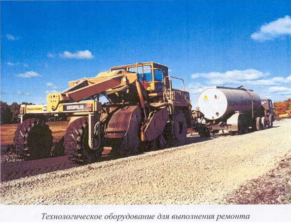
When carrying out regeneration work, a special mechanism is used: the RM-350B regenerator-mixer of the American company CATERPILLAR with a capacity of up to 1.6 km of a seven-meter road per shift. Which can perform all kinds of regeneration. The working scheme of the working body of the regenerator-mixer RM-350B is shown in the figure
Cold recycling application
When restoring damaged pavement, the most cost-effective repair methods are methods that take into account specific conditions, which is less typical in the construction of new roads. Each project is unique in terms of the structure of the existing pavement and the quality of the materials of its own and subgrade. Therefore, it is very important to choose the technology that most fully meets the conditions of this particular area of \u200b\u200bwork. The following factors should be considered:
In principle, a track is superimposed on a track that simulates traffic loads, and the structure’s response to it is measured. An analysis of this answer provides valuable information about the quality and condition of the components of the structure, as well as about problems in the subclass. Design methodology for recycling pavements Auscultation - the resulting deflections are processed to obtain a standard deviation. - If there are ruts on the sidewalk, its depth is measured at regular intervals or the characteristic value is obtained for each of the sections, which are a uniform deviation.
Location. And the choice of the most effective solution for a given country or region is influenced by local environmental conditions: such as traffic on a city street requiring repair, the ability to perform work not only at night but also during the day, the bearing capacity of a dirt road requiring urgent repair, etc. d. Already in these two cases, completely different solutions and requirements for the maintenance of roads are required. It is also important to know local standards for road construction, as well as the attitude of the local population to the quality of roads, which they regard as acceptable.
Utilization of the methodology for the design of flexible pavements for the processing of paving products receiving test tubes. The “sampling” phase is crucial not only from the moment the road section for recycling is recognized, but also as a previous step in creating a strategy for identifying sections that have similar characteristics for the job. Sampling is a general way to measure the thickness of the layers that make up the structure of the road. coverage to be restored. carried out using georadar or rotary probe.
The physical environment.When choosing the optimal recycling method, topological and geological conditions should be taken into account. Very steep slopes may require recycling as much as possible in practice. Variations in climatic conditions are most important when choosing the optimal recycling technology: for regions with low rainfall, completely different technologies are needed compared to regions where this level is high. The effects of extreme temperatures, such as cracking caused by melting-freezing cycles, should also be considered when choosing the right technology.
Availability of materials.The feasibility of various recycling options is significantly affected by the availability of the right materials, especially stabilizers. They must be available in sufficient quantities and of the required quality. Modern recyclers require a large number of stabilizers, so from the very beginning it must be determined whether they can be supplied.
MostDorStroy owns the installation “AkzoNobel"Producing bitumen emulsions according to Swedish technology with a capacity of 40 tons per hour and a crushing and screening complex for the preparation of high-strength washed cuboid crushed stone" SvedalaArbra", As well as means of delivery of materials to the place of work:bitumen trucks for delivery of bitumen emulsion with a volume of up to 30 m 3, tractors (Freightliner) with semitrailers American trailer with a loading capacity of 38 tons.

Types of cold recycling
Deep recycling
Recycling to a great depth covers a wide range of applications of this technology: to reinforce damaged pavements in order to extend their service life by an appropriate time. Subsequent application of the closing layers on top of the recycled layer increases the operational properties of the restored road, such as skid resistance, etc. The typical recycling depth here exceeds 150 mm.
Deep recycling can be used to reinforce damaged pavements with thick and thin asphalt layers.
Immediately after recycling, a new trailing layer is required. For lightly loaded roads, this can be a layer of rubble or a thin layer of hot asphalt mix. High traffic loads may require styling asphalt concrete layers, and asphalt concrete layer wear and tear.
Shallow depth recycling
Shallow depth recycling is usually performed to eliminate significant cracking of asphalt concrete layers and improve their operational quality. This type of recycling is often undertaken for the construction of roads with a short service life, but can also be used where the pavement is “healthy” and only the upper asphalt concrete layers are weakened. Recycling in this case is usually carried out to a depth of 80 to 150 mm.
Using recycling to a shallow depth, the design of pavement can be improved by laying then a trailing asphalt concrete layer. Due to the reduction of water penetration into the main layers, the service life of pavement is increased.
Reconstruction of dirt roads
Reconstruction of unpaved gravel roads by strengthening them with an organic binder can be done by treating their gravel with a bitumen emulsion followed by applying a thin crushed stone or other protective layer. The advantages of this method are the absence of dust from traffic in dry weather and safer driving conditions in rainy weather, with less chance of loss of stability by vehicles. In addition, mineral resources are much better used, since there is no need to regularly replace gravel (for dirt roads common is the annual loss of 20 to 30 mm of gravel due to transport and weather conditions) This reduces environmental damage due to the constant need to open up new quarries and quarries for the extraction of gravel. The recycling depth of this type is usually between 100 and 150 mm.
It is important to note that it is also possible to strengthen gravel roads by adding cement to their material. But then a thicker recycled layer, about 200 mm, is needed. As a result, this case should be attributed rather to recycling to a greater depth.
Comparative analysis of road reconstruction methods
I.The list of necessary work carried out with traditional reconstruction methods:
- The device of a bypass (duplicate) road;
- Dismantling the construction of the roadway with bulldozers, excavators;
- Removal of materials received from disassembly and their disposal;
- Creating a longitudinal profile;
- Stabilization (compaction) of the road base with rollers impregnated with bituminous compounds;
- The device of the sandy base of the road;
- The device of crushed stone base - 3 layers (fractions) with compaction of each layer with rollers;
- Primer with bituminous compounds;
- Device asphalt concrete pavement (by calculation);
- Arrangement of roadsides by adding soil with layer-by-layer compaction;
- A device for coating roadsides from gravel impregnated with bituminous compositions.
II.The list of necessary work carried out using the cold regeneration method:
- dry loosening to the calculated depth;
- grading of the roadway with graders;
- laying high-strength granite crushed stone on the road surface (if necessary, reinforcing the base);
- loosening to the calculated depth with the injection of bitumen emulsion;
- re-profiling of the roadway with graders;
- compaction;
- device of asphalt concrete pavement (as calculated);
- widening of shoulders if necessary.
Based on this analysis, it can be seen that the application of the cold regeneration method allows one to exclude a number of operations from the technological process. There is no need to arrange a bypass road, work associated with disassembling the roadbed, removal and disposal of the materials obtained is excluded. The device of sand and crushed stone bases is not required since during regeneration, the existing base is not damaged. The amount of equipment involved in the work is significantly reduced.
* - the cost of work depends on the specific conditions determined by the terms of reference, and on the cost of materials at the place of work.
Savings when applying the cold regeneration method is " 25% .
Advantages of the cold recycling method
- - No pollution: due to the full use of the material of the old pavement. There is no need for dump sites, and the volume of imported materials is minimal. This reduces rural clogging, which is inevitable when opening new quarries. Transportation is very small. Energy consumption is thus significantly reduced, as is the destructive effect of vehicles on the road network.
- - The quality of the regenerated layer due to the consistent, high-quality mixing of locally obtained materials with stabilizers. Liquids are injected in exactly the right amount thanks to the microprocessor pump control system. Mixing meets the highest requirements, as the components are forcedly mixed in the working chamber.
- - Structural integrity of pavement. Cold recycling allows you to get bonded layers of large thickness. Which differ in the homogeneity of the material. Due to this, liquid binders between thin layers of pavement are not required, which is sometimes necessary in pavements of traditional designs.
- - Preservation of the integrity of the soil, since when recycling, damage to low-quality soil is less compared with the use of conventional road-building machines for the restoration of pavement. Usually, recycling is performed in one pass with the RM350B recycler on pneumatic tires, which exert little pressure on the ground and, therefore, deform it a little. Under the influence of conventional machines, the soil is repeatedly subjected to heavy loads, which often leads to the need for excavations and backfill with imported material.
- - Road safety. One of the most important advantages of this technology is a high level of road safety when restoring pavement. All working machines performing regeneration are located within the width of one lane. Due to this, on two lane roads, one lane can be recycled first, and then the second, i.e. one of the lanes always remains for movement.
- - Increase in overhaul life.
MostDorStroy company has extensive experience in the field of road construction, repair and reconstruction of roads for various purposes, as evidenced by a number of concluded, including implemented, state contracts using the proposed technology.

Since 2001, MostDorStroy has performed work on the regeneration of more than 200 km of roads.
INDUSTRIAL ROAD METHODICAL DOCUMENT
Approved by
by order
Rosavtodora No. OS-568-r
january 1, 2001
MINISTRY OF TRANSPORT OF THE RUSSIAN FEDERATION
STATE ROAD SERVICE SERVICE
(ROSAVTODOR)
Moscow 2002
FOREWORD
Technical rules for the repair and maintenance of roads provide for the repair of non-rigid pavements requiring reinforcement using the traditional method and thermal profiling methods. The main disadvantage of these methods is the formation of reflected cracks in the newly laid or repaired coating layers and, ultimately, the reduction in the service life of the repaired coating in comparison with the estimated service life of the coating.
With the advent of road milling machines (cold milling machines) abroad, the method of “repacking” began to be widely used, which consists in removing cracked and lost bearing capacity of asphalt concrete layers of pavement and the construction of new monolithic layers. This method allows to obtain pavement with a service life similar to that achieved with new construction. The disadvantage is the high consumption of asphalt mixture and the high cost of work.
The latest achievement in the field of repair of non-rigid pavements is the technology of their deep cold regeneration, which allows efficient reuse of materials from old pavements. Carrying out restoration work without heating the old material causes minimal damage to the environment and dramatically reduces energy costs. In terms of economy, this technology is unparalleled. In Russia, the experience of applying cold regeneration technology is still insignificant.
When compiling the Methodological Recommendations, the following regulatory and methodological documents were used: “Cold Asphalt Concrete Regeneration”, Manual, Series 21 (MS-21), Asphalt Institute, 1983 (USA); Reference Guide to Bitumen Emulsions, Series No. 19 (MS-19), Asphalt Institute, 1987 (USA); Road Restoration Guide, Caterpillar, 1990 (USA); "Cold regeneration of asphalt concrete" in the book. "Bitumen emulsions." Basic information on application, Syndicate of manufacturers of emulsions of road bitumen, 1991 (France); “Integrated Regeneration in Road Construction”, Management, Department of Road Construction, Saxon State Ministry of Economics and Labor, 1995 (Germany); "Deep cold regeneration in place", Technical recommendations and Application Specifications, Consulting Firm and Partners, 1995 (South Africa).
IN Guidelines provides information on the scope of the new technology; assessment of the properties of asphalt concrete granulate obtained by grinding the old coating by cold milling; additives used for the preparation of asphalt-granular concrete mixtures; selection of the composition of these mixtures; assessment of the properties of asphalt granulobeton; test methods; rules for the production of work, etc.
The technical requirements for asphalt granulobeton are also given.
1. BASIC CONCEPTS
1.1. Technology of cold regeneration of structural layers of pavement (XP)consists in grinding the coating (in some cases with the capture of part of the base) mainly by cold milling; introduction to the resulting asphalt granulate (AG) if necessary, new skeletal material, a binder and, if required, other additives; mixing all the components to obtain asphalt-granular concrete mix (AGB mix);its distribution in the form of a structural layer and compaction, after which the AGB mixture turns into granular asphalt (AGB).
All these technological operations are carried out, as a rule, on the road by a link of specialized machines.
1.2. Component mixing can also be carried out in a semi-stationary installation near the road. However, this is due to the breakdown of the technological process and the addition of operations: loading and transporting AG to the place of preparation of the mixture, stacking it, feeding it to the mixing unit and transporting the AGB mixture to the place of laying, which leads to a significant increase in the cost of work.
1.3. Distinctive feature XP technology is to restore the solidity (continuity) of a package of asphalt concrete layers of pavement to all or part of the thickness without heating the asphalt concrete or AG.
1.4. On top of the regenerated layer, a closing (protective) layer or asphalt concrete coating is laid.
1.5. Elimination of cracks in the old coating to the whole or most of the depth as a result of its regeneration eliminates the appearance of reflected cracks in the above-laid layers of the coating (copying cracks). With the traditional method of reinforcing pavement, which involves laying new layers on top of the old pavement, the appearance of reflected cracks is inevitable.
2. CLASSIFICATION
2.1. Depending on the type of new binder introduced into the AH during the preparation of AGB mixtures, they are divided into the following types:
A - without the addition of a binder;
E - with the addition of bitumen emulsion;
B - with the addition of foamed bitumen;
B - with the addition of heated bitumen;
M - with the addition of a mineral binder (most often cement or lime);
K - with the addition of a complex binder (most often bitumen emulsion and cement).
AGB of the listed types are distinguished by their calculated characteristics and the rate of formation of the equilibrium structure (structure formation).
2.2. Depending on the mass fraction of crushed stone or gravel (grains of stone material larger than 5 mm), which is part of asphalt concrete from which AG is obtained, AGB mixtures are divided into crushed stone with a crushed stone content of 35% or more and sand - less than 35%.
3. TECHNICAL REQUIREMENTS
3.1. Indicators of physical and mechanical properties of AGB, depending on the category highway and the type of mixture must correspond to those indicated in table. 1.
3.2. The granulometric composition of the AGB mixture should comply with the requirements established in GOST 9128 for porous and highly porous crushed stone mixtures, with the exception of particles smaller than 0.071 mm, the content of which is not standardized.
3.3. For roads of categories I – II, crushed stone mixtures are used, and for roads of III – IV categories, sand AGB mixtures are allowed. If in the AH used for the preparation of crushed stone mixtures, the crushed stone content is less than 35%, the preparation of the AGB mixture requires the addition of the missing fraction of crushed stone.
Table 1
Name of indicator
for mixtures of type
1. The compressive strength, not less than, MPa, at a temperature of 20 ° C at the age of:
a) 1 day
b) 7 days
2. The same at age 50 ° C:
a) 1 day
b) 7 days
3. Water resistance coefficient, not less
4. Water saturation by volume,%, no more
4. REQUIREMENTS FOR MATERIALS
Asphalt granulate
Bitumen
4.2. For the preparation of mixtures using an organic binder, viscous and liquid petroleum are used. road bitumenmeeting the requirements of GOST 22245 and GOST 11955, respectively.
4.3. The bitumen brand is selected depending on the type of mixture and the climatic zone in accordance with table. 2.
table 2
Type of mixture
Bitumen grade for the climatic zone
IGO 70/130 and 130/200
Bitumen emulsion
4.4. For the preparation of mixtures of types E and K, emulsions are used that meet the requirements of GOST 18659.
In mixtures of type E, cationic emulsions of the EBK-2, EBK-3 classes and anionic emulsions of the EBA-2, EBA-3 classes are used. More preferred are cationic emulsions.
Type K mixtures mainly use cationic emulsions of the EBK-3 class.
Cement
4.5. For the preparation of mixtures of types M and K, Portland cement of at least grade 400, which meets the requirements of GOST 10178, is most often used as a mineral binder.
Crushed stone, sand, mineral powder
4.6. If it is necessary to increase the content of crushed stone in the AGB mixture (see paragraph 3.3), crushed stone that meets the requirements of GOST 8267 is added to the AH.
4.7. To adjust the granulometric composition of the AHB mixture in order to reduce the porosity of AHB, it is sometimes advisable to add sand and (or) mineral powder to the AH. These materials must meet the requirements of the relevant GOST 8736 and GOST 16557.
Water
4.8. To prepare mixtures of all types, except type B, in some cases, the addition of water is required. Usually drinkable water is used.
5. SCOPE AND TERMS OF APPLICATION
5.1. XP technology is the most economical technology for restoring the original strength of non-rigid pavement or reinforcing it.
An indication for the application of XP technology is the fractured-block state of the package of monolithic layers of pavement. Cracking occurs during the operation of the road under the influence of cyclical effects of low temperatures and moving vehicles. It is accompanied by a decrease in strength. road construction.
5.2. Often on the surface there are no visible cracks (except for through transverse temperature), although pavement requires reinforcement. This is explained by the fact that fatigue cracks arising in the sole of the package of monolithic layers have not yet reached the surface of the coating in their development.
In a first approximation, the degree of latent cracking of a package of monolithic layers of pavement can be judged by its elastic modulus, calculated on the basis of the actual (measured) general modulus of elasticity of the road structure and the estimated characteristics of the structural layers in accordance with ODN 218.046-01. If the calculated module at 10 ° C ( E10) less than 1100 MPa, then we can assume that the package of monolithic layers of pavement has a fractured-block structure or close to it. An additional confirmation of this is the inequality
(E20/E10) > 0,60, (1)
where E20 - calculated module package monolithic layers at 20 ° C.
Fig. 1. Examples of the construction of pavement, including a regenerated layer (coating, laid on top of the regenerated layer, not shown):
a - hc significantly more hp, hin » hc - hr; b - the same for hin "0; in - hc comparable to hp or less than her; 1 - a package of asphalt concrete layers of old pavement; 2 - regenerated layer; 3 - the removed part of the old coating after leveling milling; 4 - a leveling layer laid on top of the old coating and re-processed together with the material of the old coating in the regeneration process; 5 - regenerated layer of AG with the capture of part of the base layer; 6 - base layer; 7 - roadside.
7. SELECTION OF COMPOSITION OF ASPHALT GRANULE CONCRETE
Sampling
7.1. On the basis of the designed design of the pavement and the examination of the cores selected at the initial data collection stage, the areas on which grain composition the package of asphalt concrete layers to be regenerated is within the same type of mixture according to GOST 9128 (A, B, C or D).
7.2. AG samples are taken from the designated areas by milling the coating.
If the chosen design of the pavement involves the removal of the upper part of the asphalt concrete layers (see Fig. 1, a), which differs in the type of mixture from the underlying one, the sample is taken in two steps. First, the upper part of the coating is removed by milling, and then an AG sample is taken from the layer to be regenerated.
The mass of the sample from one site should be at least 30 kg.
AGB type selection
7.3. Depending on the equipment available and the design modulus of elasticity incorporated into the design, one or more types of AGB mixture are planned for research.
Bitumen, which is part of additives for mixtures of types E, B, B and K, eliminates the excessive rigidity of the aged film bitumen surrounding the granules; shields exposed surfaces of grains of mineral material as a result of milling; provides cohesion of aggregate grains added to increase the crushed stone content (Section 4.6) or to adjust the particle size distribution of the AGB mixture (Section 4.7), with each other and with AH; partially fills intergranular voids, reducing the water saturation of AHB; reduces intergranular friction, contributing to better packing of granules during compaction of the AGB mixture; contributes to the healing of microdefects arising during the operation of the regenerated layer.
Cement, which is part of mixtures of types M and K, forms a cement stone in the presence of water, which partially fills intergranular voids; reinforces the bitumen film surrounding the granules; crystallizes with non-treated bitumen grains contained in AG and aggregate.
7.4. The most technologically advanced mixtures are of type E. They are most often used for the regeneration of layers, mainly consisting of AG. The disadvantages include the possibility of rutting in heavy traffic.
7.5. Type K mixtures are more difficult to manufacture, but the AHB of such mixtures is more resistant to rutting. The use of these mixtures allows to reduce the thickness of the regenerated layer.
A layer of type K mixtures forms faster, which is especially important in adverse weather conditions.
7.6. Mixtures of type M are most often used when part of the base layer from material not treated with bitumen is captured during regeneration (more than 30% of the thickness of the regenerated layer).
AHB from such a mixture is characterized by high calculated characteristics, however, shrinkage and temperature cracks may appear in the regenerated layer.
Preparation of mixtures
7.7. Large granules are sieved from the AG sample through a sieve with holes with a diameter of 40 mm.
7.8. Mixtures of a given composition are prepared at a temperature of 20 ± 2 ° C in a laboratory paddle mixer or manually. Stirring is completed when the mixture becomes homogeneous.
7.9. If the project provides for the addition of crushed stone or other mineral aggregates to the AG, or during regeneration it is possible to capture part of the base (more than 20% by weight), the corresponding material sifted, as described in clause 7.7, is mixed with the AG in the required proportion.
7.10. In the preparation of AGB mixtures, AH should have a 2% moisture content. This simulates its natural state, in which humidity usually ranges from 1 to 3%. If the AG sample has a lower humidity, then the missing amount of water is added to it, and if it has a higher humidity, then it is dried in air or in an oven with forced ventilation at a temperature of no higher than 40 ° C to the required humidity. Before preparing the AHB mixture in this case, it is necessary to cool the sample of AH to a temperature of 20 ± 2 ° C.
To simplify the dosing of water, the AG sample can be dried in advance to a constant weight.
In the preparation of an AGB mixture of type M, a cement is first introduced into the AH with a moisture content of 2%, and after its uniform distribution in the mixture, an additional amount of water is introduced.
7.11. When preparing an AH-mixture of type K, an emulsion is first introduced into the AH with a moisture content of 2%, and after its uniform distribution in the mixture, cement is introduced.
If according to the accepted technology it is supposed to introduce cement in the form of a suspension, then in laboratory conditions a cement suspension with a ratio W / C \u003d 0.5 and an emulsion are introduced into the AG at the same time.
The compatibility of these two types of binder is preliminary determined by adding 150 g of suspension (100 g of cement + 50 g of water) to 100 g of emulsion and mixing them continuously in a glass beaker with a glass rod.
The process of decay of the emulsion should begin no earlier than 4 minutes from the start of mixing.
Production of samples and their preparation for testing
7.12. The physical and mechanical properties of AGB are determined on cylindrical samples with a diameter of 71.4 mm (40 cm2 in area) made by pressing under a pressure of 7 MPa, in standard forms for the manufacture of asphalt concrete samples (GOST 12801), at a temperature of 20 ± 2 ° С. The sample holding time at a given pressure is 3 minutes.
7.13. The height of the sample should be 71.4 ± 1.5 mm. The approximate amount of the mixture per sample g. It is specified in the manufacture of a test sample for asphalt concrete (Section 3.5. GOST 12801).
7.14. During the pressing process, excess water should be released through the gap between the lower punch and the mold. If the clearance is insufficient, vertical slots with a width and depth of 2 mm must be made on the punch from four sides.
7.15. After manufacture, the samples are stored indoors at a temperature of 20 ± 2 ° C and air humidity% until the test.
7.16. Before the test, the samples are dried to constant weight in air or in an oven with forced ventilation at a temperature not exceeding 40 ° C. In the latter case, they should be cooled to room temperature before testing.
TEST METHODS AG AND AGB
Determination of bitumen content in AG
Determination of crushed stone content in AG
Determination of particle size distribution of AG
7.19. The particle size distribution of the AG is determined according to GOST 12801.
The difference is that bitumen is not removed from the sample weighing 500 g, sieving is carried out dry.
Determination of true hypertension density
7.20. True AG density ( gig) is determined by the picnometric method according to GOST 12801. A sample is taken with a mass of at least 300 g. It is recommended to use a volumetric flask with a capacity of 1000 cm3 and a neck diameter of at least 15 mm.
The AG sample must first be dried to a constant weight, and granules larger than 15 mm should be crushed with a hammer.
Determination of the average density of AGB
7.21. The average density of AGB ( ga) is determined in accordance with GOST 12801, taking into account clause 7.16 of the Methodological recommendations.
Determination of residual porosity AG
7.22. The residual porosity of the AG ( Vg) is closely related to the residual porosity of the regenerated package of coating layers and can be very different for AG fractions of different sizes. For subsequent calculations, you can accept
where VA - residual porosity of a core drilled from the coating to be repaired and tested after removal of layers not affected during the regeneration process, according to GOST 12801.
Usually, Vg is in the range of 1 - 2%.
Calculation of intergranular voidness of AGB
7.23. Intergranular voidness of AGB ( Vm) is the most important structural characteristic of AGB, on which its physical and mechanical properties substantially depend.
Lower value Vm, defined for AHB without additives, the higher the quality of AH and the smaller the amount of additives required to obtain an AHB mixture of optimal composition.
Intergranular voidness of AGB samples without additives of binders (from AH with a moisture content of 2%) ( Vmg
where gag - the average density of AGB without additives binders (see p. 7.21), g / cm3;
gg - average AG density, g / cm3.
The average AG density is calculated with an error of 0.01 g / cm3 according to the formula
where gng - true AG density (see clause 7.20), g / cm3;
Vg - residual porosity of the AG (see p. 7.22).
Intergranular voidness of AGB samples with additives of binders ( Vm) are calculated with an error of 0.1% according to the formula
where ga - the average density of AGB with the addition of binders (see p. 7.21), g / cm3;
D - mass fraction of binder additives in excess of 100% AG,%.
For AGB mixtures of various types, the parameter D takes the following values:
D = B, (6)
where B - mass fraction of bitumen (types B and C);
D = 1,3 Ts, (7)
where Ts - mass fraction of cement, and 1.3 - coefficient taking into account the proportion of water that has reacted during the formation of cement stone (type M);
where E - mass fraction of the emulsion;
TO - concentration of bitumen in the emulsion,% (type E);
Accounting for aggregate additives to AG
7.25. In the case of adding aggregate to the AG (paragraph 7.9), formula (3) will take the form
where is the average density of AGB with the addition of aggregate, but without the addition of a binder (see clause 7.21);
The average density of AG with the addition of aggregate, calculated by the formula
where 3 - mass fraction of aggregate in excess of 100% AG,%;
gg - the average density of the AG calculated by the formula (4);
gs - true aggregate density, g / cm3 (crushed stone according to GOST 8269, sand according to GOST 8735 and mineral powder according to GOST 12784).
Accordingly, formula (5) takes the form
where is the average density of AGB with aggregate and binder additives (see clause 7.21);
D - mass fraction of binder additives in excess of 100% AG, determined by one of the formulas;
Determination of water saturation AGB
7.26. AGB water saturation (W
The aging time of the samples in a vacuum device and then at atmospheric pressure is 30 minutes each.
Determination of the ultimate strength of AGB in compression
7.27. The ultimate strength of AGB in compression at 20 ° C ( R20), 50 ° C ( R50) and in a water-saturated state ( Rin) are determined according to GOST 12801.
Before testing, the samples are kept in air at a given temperature for at least 2 hours
Determination of the water resistance coefficient of AGB
7.28. Water resistance coefficient AGB ( Kin) are determined according to GOST 12801.
Selection of the composition of the AGB
7.29. For mixtures of types B and B, four batches of AG are prepared with a moisture content of 2%: with the addition of 1.0, 1.5 and 2.0% bitumen (in excess of 100% AG by weight) and comparative - without the addition of bitumen. 2 kg of AG are required per batch.
Three samples are pressed from the mixtures prepared as indicated in p.p. (see p. 7, and after one day of storage (see p. 7.15), after preparation for testing (see p. 7.16), determine average density of samples.
In order to simplify the test, the sample volume ( V) are calculated with an error of 1 cm3 according to the formula
where is the average value of the height of the sample from four measurements with a caliper at points equally spaced from each other around the circumference of the sample, with an error of 0.01 cm;
S - sample area equal to 40 cm2;
6 cm3 is the approximate difference between the volumes determined by geometric and hydrostatic methods.
The average density of the sample ga or gag determined with an error of 0.01 g / cm3 according to the formula
where go - the mass of the sample, weighted with an error of 1 g in air.
For the average density for each series of samples take the arithmetic average of the results of determination of the density of three samples. The discrepancy between the results of parallel determinations should not exceed 0.03 g / cm3.
The granule packing coefficients are calculated for each series of samples from AGB with different bitumen contents according to formulas (10) or (14).
After determining the average density, the samples are tested for compression at 20 ° C (see paragraph 7.27).
The optimum content is bitumen, at which the samples show the maximum value of the indicator R20. As a rule, in samples from such a series, the value of the indicator is also Kg.
If the average R20 for two adjacent series differs by less than 0.1 MPa, preference should be given to AHB with a higher value of the indicator Kg.
Depending on the trend of indicators Kg and R20 with a change in the bitumen content, it may be necessary to make additional batches with a different bitumen content: less than 1.0% or more than 2.0%.
If the indicator R20 for a series with optimal bitumen content does not meet the requirements of table. 1, you should try to adjust the particle size distribution of the AGB mixture (see section 4.7) or switch to a mixture of types K or M.
7.30. For mixtures of type E, the procedure for selecting the optimal AGB composition is similar to that described in clause 7.29.
The main batches are prepared with the addition of 2.0, 3.0 and 4.0% emulsions.
In mixtures of this type, the water content, as a rule, turns out to be excessive, and excess water is squeezed out when pressing the samples.
The average density of the samples is determined in a simplified way and the compression test at 20 ° C is carried out 7 days after their manufacture, since the AHB on the emulsion takes time to form a bitumen film.
7.31. For mixtures of type M, the main batches are prepared with the addition of 2.0, 3.0 and 4.0% cement and the addition of 1.0 and 2.0% water (in excess of 100% AG by weight) in the last two mixtures, respectively (in addition to 2% water contained in AG).
If any of these mixtures does not mix well, increase the water content by 0.5%.
The optimum is the content of cement, at which the samples achieve the maximum value of the indicator Kg. The value of the indicator R20 must comply with the requirements of table. 1. Otherwise, you should try to adjust the particle size distribution of the AGB mixture (see section 4.7) or increase the cement content, but not more than 5%.
7.32. For mixtures of type K, the content is prescribed: cement 3%, and emulsions - 2.0, 3.0 and 4.0% (in excess of 100% AG by weight). If 2% humidity of AG is provided, no water is added to the mixture.
The rest of the procedure for selecting the optimal composition of AHB is similar to that described in paragraph 7.30.
The optimal content of the emulsion, in which the samples have a maximum value of the indicator Kg.
With an increase in the cement content in the mixture, the short-term elastic modulus ( Ep) For example, with the same emulsion content of 3% and cement contents of 2.0, 3.0 and 4.0%, the corresponding values Ep the regenerated layer at 28 days of age at 10 ° C can reach 1700, 2950 and 4250 MPa.
The emulsion reduces the short-term modulus of elasticity of the regenerated layer of type K mixtures by about 20%, compared with type M mixtures.
The optimal ratio between the cement and emulsion contents in the mixture is 50:50, but variations from 60:40 to 40:60 are allowed.
If the indicator R20 is at or below the requirements of table. 1, and the adjustment of the particle size distribution of the AGB mixture is undesirable from economic considerations, it is possible to increase the cement content (but not more than 5%) and repeat the procedure for selecting the optimal emulsion content.
7.33. Having selected the composition, make the appropriate mixture to check the remaining physico-mechanical properties of AGB. For kneading 4 kg of AG are required.
Six samples are pressed and after 24 hours or 7 days (depending on the type of AGB mixture) their average density is determined (see 7.21). After that, the samples are divided into two groups of three samples so that the arithmetic average of the results of determining the density in each of the groups are as close as possible.
Water saturation is determined for three samples of one of the groups (see clause 7.26), as well as indicators Rin (see clause 7.27) and Kin (see clause 7.28). This is done immediately after determining the average density. When calculating water saturation, the mass values \u200b\u200bof samples suspended in air, obtained by determining their average density, are used.
Before defining an indicator R50 (see paragraph 7.27) samples from the second series are dried (after determining the average density) to constant weight.
If the indicator W or Kin do not meet the requirements of the table. 1, one should either adjust the particle size distribution of the AHB mixture, or increase the binder content in mixtures of types B, C and E, or switch to mixtures of types K or M, for which, as a rule, there are no problems with these indicators.
If the indicator R50 does not meet the requirements of table. 1, which sometimes occurs for mixtures of types B, C, and E, it is necessary to switch to mixtures of types K or M, for which the required value of this indicator can always be ensured by increasing the cement content.
8. RULES OF WORK
TECHNOLOGICAL DIAGRAMS
8.1. The choice of the technological scheme for the production of works depends on the purpose of the repair, the category of the road, the design of the pavement, and its condition.
The technological scheme is developed by the contractor on the basis of the project, the equipment available to him and the selected type of AGB mixture.
8.2. In fig. 2 shows the schemes of work in which the milling operation is separated from the rest of the operations.
After leveling the pavement (see clause 6.5) using a road milling machine (hereinafter referred to as milling cutters), regenerative milling of a package of asphalt concrete layers to the design depth is carried out. The resulting AG through the conveyor, available on the cutter, enters the receiving hopper of the mixer-stacker. From there it enters a horizontal twin-shaft mixer, where it is mixed with an organic binder. The finished mixture is laid and compacted.
Fig. 2. Technological schemes of XP using a mixer-stacker as the leading machine:
1 - roller; 2 - mixer stacker; 3 - a mill; 4 - pick-up; 5 - roller AG; 6 - dump trucks; 7 - AG warehouse.
According to the scheme (Fig. 2, a), the milling cutter works in conjunction with a stacker mixer, which is the leading machine. The performance of the mixer-stacker is t / h, which corresponds to a working speed of 2 - 3 m / min. The thickness of the stacked layer is up to 12 cm. Since the working speed of the cutter is m / min, it is obvious that its productivity will be artificially underestimated at least three times.
The stacker mixer has two sliding expanders, which allows you to vary the laying width from 2.4 to 4.2 m. It follows that the minimum milling width should be 2.4 m.
The disadvantage of this scheme is that during a malfunction or maintenance of one of the machines, the entire flow stops.
According to the scheme (Fig. 2, b), the milling cutter leaves the AG on the roadway in the form of a prism. It is picked up by a towed or self-propelled pick-up, working in couple with a mixer-stacker, and sent to the receiving hopper of the latter. Here, the performance of the cutter does not depend on the performance of the host machine.
Regenerative milling can be combined with leveling (Fig. 2, c). In this case, the milling cutter works in one link with dump trucks that deliver the main volume of AG to the stacker mixer, and the excess AG to another object or warehouse.
A variant is also possible in which the work of the cutter is not linked to the work of the mixer-stacker. AHs are stored in roadside warehouses, from where they are shipped by a loader to dump trucks and sent to a stacker mixer.
The cheapest and most technologically advanced is the second option.
The mixer-stacker is primarily adapted to work with mixtures of type E. It has a capacity for storing 10 tons of emulsion and a metering device.
If it is necessary to increase the gravel content in the AGB mixture or adjust its particle size distribution, the new material is distributed with an even layer of the required thickness over the coating before or after regenerative milling.
8.3. In fig. Figure 3 shows the flow diagram using a remixer freed from gas equipment to heat the coating as a stacker mixer. Here, the regenerative milling operation is also separated from the remaining operations.
After the cutter passes, the grader profiles the prisms of the AG with an even layer over the entire width of the regenerated strip.
The mixer-stacker (hereinafter referred to as the regenerator) makes it possible to prepare mixtures of types E, M and K. A special machine is equipped with it, equipped with silo banks for storing emulsion, cement and water (Fig. 3, a). Material for adjusting the particle size distribution of the AGB mixture can be discharged directly into the receiving hopper of the regenerator.
A pick-up is not required to supply AG to the mixer. This operation is performed by special augers.
The width of the laying can be changed in the range from 3.5 to 4.5 m, which, as in the case of the mixer-stacker, facilitates the performance of a multiple number of passes along the width of the coating.
The thickness of the stacked layer is up to 30 cm; working speed - up to 16 m / min; productivity - about 300 t / h.
On the regenerator there are containers for storing emulsion, cement and water, which are replenished from a car with silo banks.
The dosage of the components is controlled by microprocessors.
Fig. 3. Technological schemes of XP using a regenerator as a leading machine:
1 - roller; 2 - regenerator; 3 - a machine with silo banks for the main components of the mixture; 4 - grader; 5 - a mill; 6 - emulsion carrier; 7 - suspension.
Recently, a technology that provides for the addition of cement and water in mixtures of types M and K in the form of cement paste (slurry) is becoming more widespread. For its preparation on the regenerator there is a corresponding device. A special machine is also used - a suspension device. In fig. 3b shows the XP scheme with the preparation of a mixture of type K with the addition of a suspension.
8.4. A machine was also created combining regenerative milling operations with the preparation and stacking of an AGB mixture. This machine works complete with a special dosing machine equipped with silo cans for emulsion, cement and water. It also allows the preparation of mixtures of types E, M and K.
Later it was deemed more appropriate to separate the milling function by providing it to the milling cutter, and thereby facilitate the main machine.
8.5. The technological scheme, providing for the combination of all basic operations with one machine, is presented in Fig. 4.
Fig. 4. Technological scheme of XP using a milling machine-regenerator as the leading machine and manufacturing a mixture of type E:
1 - roller; 2 - mill-regenerator; 3 - emulsion carrier.
Here, a track-type mill-regenerator is used as a leading machine.
Aging with additives is mixed under the milling drum casing, and for laying the AGB mixture there is attachment similar to that installed on conventional pavers.
Included with this machine is an emulsion carrier - a tank truck for transporting, storing and feeding the emulsion (when preparing a mixture of type E) and (or) a suspension (when preparing mixtures of types K or M).
Previously, cement was distributed over the coating before milling with a special cement distributor, but this operation was not technologically advanced due to the dustiness of the cement. The use of cement paste eliminated the noted drawback.
Adding a new mineral material (if necessary) is carried out as described in paragraph 8.2.
The width of the milled strip is 2 m, but in a special version it can be increased up to 2.5 m. The milling depth reaches 30 cm.
The operating speed of the machine substantially depends on the milling depth and averages 5 to 7 m / min.
The regenerator has dispensers for water and emulsion. A special clamping device prevents the formation of large pieces of asphalt during the milling process. Vibrating ram working element allows to achieve a high degree of preliminary compaction of the mixture.
The quality of mixing the mixture with this machine is lower than when using the machines described in paragraphs, since the latter are equipped with special twin-shaft mixers, and here the mixing is carried out by the milling working body without homogenizing the mixture in the transverse direction.
8.6. In fig. 5 shows technological diagrams using a milling cutter-soil mixer (hereinafter referred to as a stabilizer) on a wheeled drive as a leading machine. This machine is much simpler than those mentioned above, although it combines the basic operations.
As a rule, the stabilizer operates on a two-pass circuit. First, he mills the pavement to a predetermined depth, and the grader levels the prism of the AG (Fig. 5, a). Then he mixes AG with additives during a second pass.
Fig. 5. Technological schemes of XP using a stabilizer as the leading machine:
a - preliminary milling of the coating; b, c, d, d - production of mixtures of types: E, M, B, K, respectively; 1 - grader; 2 - stabilizer; 3 - skating rink; 4 - emulsion carrier; 5 - water carrier; 6 - cement distributor; 7 - bitumen truck; 8 - suspension
Dosage of bitumen, emulsion and water is carried out by pumps controlled by microprocessors, and cement dough - by a pump of a suspension. Aging with additives occurs under the milling drum casing. A height-adjustable sweeping blade located behind the milling drum improves mixing quality.
The width of the milled strip is 2.44 m, and the milling depth reaches 50 cm. The average working speed during milling (first passes / min, and when mixing (second passes / min.
Depending on the type of AGB mixture, the stabilizer works complete with auxiliary machines (Fig. 5, b - e).
Unlike a regenerator mill, this machine does not have special equipment for distribution, smoothing and preliminary compaction of the mixture. The mixture levels the grader. Hence, the evenness of the layer and the correspondence to a given transverse profile will be lower than according to the previous schemes.
The stabilizer as the leading machine is used for XP, usually on secondary roads.
8.7. All of the above technological schemes are united by the fact that the AGB mixture is prepared directly on the road in the process of moving the construction stream. However, a scheme is possible in which the AG obtained during the milling process is stored near the road. In the same place, at a semi-stationary mixing plant, a mixture is prepared, which is transported to the place of laying.
The disadvantages of this technology have already been mentioned in paragraph 1.2.
Milling
8.8. For milling coatings, various foreign companies offer a large number of mills, differing in the width of the milling drum, engine power, milling depth and other parameters. Many of them are equipped with devices for collecting AG and loading it into dump trucks.
Most often, cutters with a width of the processed strip - 2.0 - 2.5 m are used.
8.9. For leveling milling, including alignment of the coating in the longitudinal direction, the cutter must be equipped with automation that allows you to work on a string or with a leveling beam (on wheels) with a length of 5 - 7 m (it is supplied by companies on an individual order).
When aligning along the string, it is pulled onto metal pins installed at a certain distance (depending on the design of the tracking device) from the center line (less often, the edges of the coating) in steps.
The first cutter pass is performed along the string, setting (on the axial side) the required milling depth and the slope of the milling drum, and the subsequent ones using a copier sliding on the level surface of the underlying layer.
Before leveling milling, it is advisable to make leveling backing of the coating in places where it is provided by the project, using AG or asphalt mix. The leveling mixture is rolled.
8.10. The direction of rotation of the milling drum depends on the milling depth hin or hp and thickness of the package of asphalt concrete layers hc (fig. 6):
When leveling milling, when hin < hc, and regenerative milling when a layer of incoherent base is not captured ( hin + hp < hc), the milling drum is rotated “from top to bottom” with respect to the direction of flow;
In cases where hin ≥ hc or hin + hp ≥ hc, that is, the milling boundary passes between the asphalt concrete and incoherent layers or lower with the capture of the material of the latter, the rotation of the milling drum is carried out “from bottom to top”.
Fig. 6. The direction of rotation of the milling drum, depending on the depth of milling and the thickness of the package of asphalt concrete layers.
8.11. The size of the AG depends on the design of the milling organ, the rotation speed of the milling drum, the working speed of the mill, the depth of milling, type of asphalt concrete and other factors.
The narrower the back slit under the casing of the milling drum, the longer the AG is retained inside the casing and crushed more. The maximum size of the AG cannot be smaller than the maximum size of the gravel that is part of the AG.
The higher the rotation speed of the milling drum, the finer the AG in granulometry. Usually, when milling thick coatings (more than 15 cm), the first speed is used; coatings of average thickness cm) - the second speed; thin coatings (less than 8 cm) - the third speed.
The stronger the coating, the lower the rotational speed of the milling drum is required for grinding asphalt.
The third controlled factor is the working speed of the cutter. The smaller it is, the smaller the resulting hypertension.
8.12. During the milling process of the coating, the teeth of the milling drum wear out. Replacing them is the most expensive operation and a factor that reduces productivity. Hardness of asphalt concrete, milling depth, coating temperature and other factors affect tooth wear. The most favorable temperature for the operation of the teeth ° C. On average, every 10 thousand m2 of coverage requires the replacement of all teeth.
A spontaneous decrease in the working speed of the cutter indicates a strong wear of the teeth. Working with worn teeth can damage the tooth holders, which will require welding work and, consequently, a delay in flow.
The teeth must be checked regularly every 2 hours or at the end of the grasp.
During inspection, the most worn or damaged teeth are replaced. Typically, the cause of the destruction is a tooth falling onto metal objects buried in the coating or large stones.
The teeth require replacement in the cases shown in Fig. They are removed from the holder or inserted into it using a special puller, which is part of the tool. Two people can replace all teeth in an hour.
Fig. 7. Types of wear and fracture of milling teeth:
1 - a new tooth; 2 - tooth with an erased middle part; 3 - tooth with an erased side; 4 - tooth with a partially destroyed tip; 5 - tooth with a worn tip.
Some of the removed teeth, suitable in length, can be used to replace the broken ones.
8.13. It is difficult to specify the performance of the cutter due to the large number of influencing factors. Usually it is determined in the experimental section or taking into account the existing experience in such conditions. If the operating speed in these conditions is determined, then the productivity is determined simply.
For example, if the width of the processed strip is 2.42 m, the working speed is 10 m / min and the coefficient of use of working time is 80%, the hourly productivity will be:
2.42 · 10 · 60 · 0.80 ”1200 m2.
Mixing on the road
8.14. Before starting work, it is necessary to carry out a project of their organization, taking into account the selected technological scheme (see above).
In the project of the organization of work, you must first indicate:
The scheme of organization of movement (see. "Instructions for the organization of movement and fencing of production sites road works", M. -" Transport ", 1985);
Estimated average operating speed of the host machine;
The technological scheme of work with the distribution of mechanisms for private captures;
Interchangeable gripper length
The number of passes of the driving machine along the width of the carriageway and their sequence;
The need for added materials;
Measures to level the pavement (if provided for by the main project);
Location of AG warehouses (if provided by the technological scheme);
Quality control measures.
8.15. The most important event before the start of the main work is the installation of a test site. In this case, the following parameters are specified:
a) Granulometric composition of AG. If it is very different from that established during the selection of the AGB composition (see paragraph 7.19), it may be necessary to adjust the selected composition.
Correction of AG size can be done by varying the controlled parameters of milling (see section 8.11).
b) Humidity of the AG after milling and the kinetics of its change during the day. These data are necessary for calculating the amount of added water during the preparation of the AGB mixture.
in) The quality of mixing.
d) Optimum humidity.
Compaction of samples under laboratory conditions weakly simulates the process of rolling the mixture. Optimum humidity ( Wabout) it is advisable to determine on the trial plot. To do this, lay three sections with different water contents, and the next day, after the evaporation of water, determine the density of the AGB radio density meter. Usually, when there is a lack of moisture on the surface of the layer during the rolling process, transverse hairline cracks appear, and when there is an excess of moisture, a “wave” forms in front of the roller of the roller, and the mixture begins to stick to it.
Tentatively Wabout can be determined in laboratory conditions by pressing samples from mixtures with different water contents under a pressure of 3 MPa. The criterion is the average density determined by the simplified method (see clause 7.29). Humidity will be optimal at which the average density reaches its maximum value, and a further increase in humidity leads to the extraction of water during pressing.
For mixtures without the addition of untreated skeletal material Wabout »2 ÷ 3%. Given the natural humidity of the AG and the water contained in the emulsion, for mixtures of types E and K there may be no need to add wetting water.
e) Density of AGB. This parameter is the main one for assessing the quality of AGB. It depends on a large number of factors, including an uncontrolled factor - the temperature of the hypertension at the time of compaction. The higher it is, the ceteris paribus the higher the density of AGB. Establishment of a really achievable density (base) allows further operational control of the quality of preparation and compaction of the AGB mixture.
e) The average operating speed of the driving machine. The flow productivity and all economic indicators depend on it. The desire to increase it should not affect the quality of AGB.
g) The thickness of the stacked layer. In order to obtain the required thickness of the regenerated layer after rolling, when using a stacker mixer, a regenerator mill, a regenerator, and other machines equipped with a layer-forming device, it is necessary to correctly adjust the height of the exit slit of this device (as on pavers).
8.16. The use of technological schemes in which the milling operation is separated from the rest of the technological operations makes it possible to combine leveling and regenerative milling. In this case, the milling drum is adjusted to the required elevation of the bottom of the trough (the sole of the regenerated layer). The excess AG in places where leveling milling is provided is moved by a grader to the side of the road or dump trucks to a roadside warehouse for subsequent use in areas where there is not enough AG to regenerate the layer (see Fig. 1, b and c). If such sections are located on the half of the carriageway of the road where the work is being carried out, the excess AG is immediately taken out to them (within the limits of the capture closed to public transport) or to other sections where the movement may be closed.
After milling the entire repaired half of the carriageway, the AG prisms are planned by an autograder with the creation of a layer of as uniform thickness as possible with the required transverse slope. The number of passes of the grader should be minimized so as not to condense the AG layer before regeneration.
8.17. If the project provides for the adjustment of the particle size distribution of AG, the new mineral material is distributed over the coating before regenerative milling. Adding new material after milling is undesirable. It is associated with the passage of construction vehicles through the AG layer, which leads to the adhesion of granules.
In the case under consideration, the combination of leveling and regenerative milling makes it difficult to maintain the required proportion between the volumes of AG and the new material, since the thickness of the milled layer becomes variable over the width of the coating. These difficulties disappear when equalizing milling is performed before the distribution of the new material.
8.18. Before regenerative milling in the area where, due to the large transverse slope, a leveling layer device is required, the required amount of AG or asphalt concrete mixture is imported, which is distributed by the grader. In long stretches, an asphalt paver can be used. The layer should be rolled in to allow the movement of construction vehicles along it.
If a hot asphalt mixture is used for leveling, its composition should be close to the component composition of the AG.
8.19. Regenerative or combined milling is carried out, as a rule, along the string. Therefore, all work associated with the installation of the string must be performed on the appropriate grip. Most milling cutters provide milling of the coating to specified marks with an accuracy of ± 0.5 cm.
8.20. The number of passes of the driving machine depends on the width of the laid strip and the roadway being repaired.
If the driving machine provides for the possibility of laying a layer with a gable profile, then the number of its passes along the width of the carriageway may be odd (the axis of one of the passages coincides with the axis of the carriageway). In this case, the string is installed on the curb at the edge of the coating, and the first pass is made from the curb.
When using a mixer-stacker or regenerator as the driving machine, adjacent strips are laid up close. In other cases, their overlap is necessary.
The minimum overlap width of adjacent strips should be 5 cm greater than the thickness of the regenerated layer.
The use of machines with a variable width of laying allows to minimize the number of passes and minimize the width of the overlap of the strips where it is provided.
Width of overlap ( P) is determined by the formula
where n - the number of passes of the driving machine along the width of the carriageway (or its half), rounded upwards to an integer;
bp - width of the laid strip, m;
b - width of the carriageway (or its half), m.
If it turns out that P < Pmin (minimum overlap width), increase the number of passes per unit and repeat the calculation.
For example, when b \u003d 8 m Pmin \u003d 0.15 m, and bp \u003d 2.5 m n \u003d 8: 2.5 \u003d 3.2. Round to an integer: n \u003d 4. By the formula (17)
The result satisfies the inequality P ≤ Pmin. If here b - the width of half of the carriageway, and the machine allows you to lay a layer with a gable lateral profile, you can reduce the width of the overlap and the number of passes: n \u003d 2 · 8: 2.5 \u003d 6.4. Round to 7.
Finally n = 7; P \u003d 0.25 m.
8.21. When the scheme of work involves the overlap of adjacent sections, its value is taken into account in the calculations of the consumption of additives. For the first pass, the calculation is carried out for the entire length of the milling drum, and for the rest, it is reduced by the width of the overlap.
8.22. Capture Length ( L) should be such that in a working day it is time to regenerate the coating over the entire width of half of the carriageway (on which traffic is blocked) with an even number of passes or with capture of a part of the oncoming traffic strip with an odd number of passes of the host machine.
If a regenerator is used as the host machine, which performs all operations in one pass, the length of the gripper is calculated by the formula
where m - the number of hours in daylight;
FROM - the coefficient of use of working time (refueling, tooth replacement, maneuvering, etc.);
V - the operating speed of the host machine, set when the trial plot was installed, m / min;
n - the number of passes of the host machine (see paragraph 8.20).
For example, when m \u003d 10 hours FROM = 0,8, V \u003d 6 m / min and n = 4
We round up to 700 m. Thus, the length of a day grab 8 m wide can be taken equal to 700 m.
When using a host machine that requires preliminary milling of the coating, the day grab will consist of two private grippers: the mill will work on the first and the host machine on the second (for example, a mixer-stacker). The total length of the daily capture in this case may exceed 1 km.
If the AGB mixture contains cement, a stacker mixer or regenerator (not performing the milling operation) is used as the host machine, and if the number of passes is more than one, the gripping length is calculated by the formula
Lg = 60 t C V,
where t - setting time of cement paste, h, t ≤ 3 h;
FROM and V are the same as in formula (19).
For example, when t \u003d 2 hours FROM \u003d 0.8 and V \u003d 3 m / min Lg \u003d 2 · 60 · 0.8 · 3 »300 m.
With two passes along the width of the roadway being repaired, the work on the first grab will be completed in 4 hours. In an eight-hour working day, the total length of the interchangeable gripper will be 2 · 300 \u003d 600 m.
If the mixer-stacker or regenerator processes the second lane, moving in the opposite direction, you will have to accept t \u003d 1 h and the length of the private capture is reduced by half.
Here, the limitation of the length of the grapple is associated with the need to seal the mating zone of adjacent strips before the rigidity of the mixture increases significantly due to the setting of the cement paste.
If necessary, alignment of the coating according to a scheme that excludes the combination of leveling and regenerative milling, it can be carried out either at the first private capture, sequentially with regenerative milling, or should be carried out ahead of the main stream.
8.23. The thickness of the regenerated layer of AGB is always greater than the depth of regenerative milling. This is due to the difference in the densities of the AGB and the initial package of asphalt concrete layers: usually 2.10 - 2.20 g / cm3 in the first and 2.30 - 2.40 g / cm3 in the second.
The ratio between the thicknesses of the milled layer and the layer of AGB, with the full use of AH in the latter, is determined by the formula
where hr - thickness of the compacted regenerated layer, cm;
ha - depth of regenerative milling (thickness of the milled layer excluding leveling milling), cm;
D - mass fraction of additives, excluding water,% (in excess of 100% AG) (in mixtures with cement, its share is increased by 1.3 times taking into account the water entering into the reaction);
ga and gr - the average density of the packet of layers of the old coating and the regenerated layer (after drying), respectively, g / cm3.
For example, when ha \u003d 15 cm, the content in AGB of 3% cement and 2% 60% emulsion, ga \u003d 2.37 g / cm3 and gr \u003d 2.15 g / cm3, D = 1,3 Ts + 2 · 0.6 \u003d 5.1%, and
Therefore, the thickness of the regenerated layer will be 2.4 cm more than the thickness of the layer milled after the coating is leveled.
Given the above, when designing pavement (see section 6), the estimated thickness of the regenerated layer is laid in the project, i.e. hrand depth of regenerative milling ha determined by the formula
Since the density of the regenerated layer is variable and can vary within ± 0.05 g / cm3 during the work, the thickness of the regenerated layer can fluctuate within ± 0.5 cm, which is not significant.
If the AGB mixture is leveled without preliminary compaction with a vibrating plate, then the thickness of the layer in the loose body should be approximately 30% greater than the thickness of the layer after the final compaction.
If the AGB mixture is leveled with pre-compaction with a vibrating plate, then after the final compaction, the thickness of the regenerated layer will decrease by about 6%.
8.24. Leading machines stack the mixture along the string.
Mixing in a stand-alone installation
8.25. Preparatory work and the organization of movement in the production of work by the considered method are similar to those described in paragraph 8
8.26. The operations of leveling and regenerative milling are combined here. All AG are transported to the roadside warehouses.
8.27. For the manufacture of AGB mixtures, an easily mounted and dismountable semi-stationary unit equipped with a forced-action mixer and dispensers of liquid and bulk materials is used. Most often, continuous installations are used.
For storage of liquid and bulk additives, silo banks and tanks are used, equipped with a system for supplying additives to mixer dispensers.
8.28. AG must be in warehouses in the form of cones or prisms up to 2 m high. In higher heaps, AG is prone to caking, especially in hot summer weather.
When bulging an AH with a bulldozer or a loader, avoid hitting wheels or tracks on the AH. Otherwise, the granules stick together (AG caking).
When unloading dump trucks and hilling, large granules roll down to the base of the cone, which leads to the delamination of the AG.
The caked AG should be passed through a special grinder, which kneads large pieces, but does not crush the granules.
8.29. AG is fed to the conveyor leading to the mixer or into the storage hopper of the mixing plant, by a loader. A set of loader bucket is carried out from below the cone or prism.
8.30. When using installations cyclic action on the quality of the mixture may affect the sequence of the introduction of additives. For mixtures of types E and K, wetting water is injected into the mixer, and then an emulsion. For a mixture of type M, cement is first introduced and then water. For a mixture of type K, cement is introduced last.
When using continuous installations, all additives are administered simultaneously.
8.31. The amount of wetting water is specified taking into account the natural humidity of the AG, the water contained in the emulsion, and the optimal humidity of the mixture (see paragraph 8.15).
8.32. The finished mixture is delivered to the paver by dump trucks. Delivery time when working with mixtures of types M and K should not exceed 2 hours, in order to avoid increasing the rigidity of the mixture.
8.33. In order to eliminate longitudinal joints or reduce their number, it is advisable to lay the mixture with several stackers or one wide spreader over the entire width of half of the carriageway. Otherwise, the number of passes is determined by the formula (18).
Adjacent stripes are laid back to back.
8.34. Laying the mixture is carried out on a string.
8.35. The length of the grips is assigned as described in clause 8.22.
8.36. The thickness of the layer emerging from under the stacker plate is adjusted taking into account the information set forth in clause 8.23.
8.37. On roads of III - IV categories, a grader can be used to level the mixture.
Compaction of asphalt mixes
8.38. When using a mixer-paver, regenerator or conventional paver as the leading machine, the preliminary compaction is carried out with a vibrating plate or tamper, and the final one with rollers.
8.39. There is no need to rush with the compaction rollers of an AGB mixture of type E. If, for technological reasons, the water content in it turned out to be higher than the optimum, it is advisable to wait a few minutes) to allow the excess moisture to evaporate.
8.40. Sealing is carried out in the following order:
Vibro - or combined roller weighing 6 - 8 tons of passage;
Smooth roller rink with mass passes;
Pneumatic tire roller weighing over 16 tons - over 4 passes.
Rolling continues until the cessation of the layer.
8.41. In the process of compaction, the rollers should move from the edges to the axis of the road, and then in the reverse order with the overlap of each track.
When compacting the first strip, the rollers of the roller should be at a distance from the edge of the interface. Sealing the second strip should begin with mating.
8.42. The time from the preparation of AGB mixtures containing cement to the end of their compaction should not exceed 3 hours
8.43. After passing the roller on pneumatic tires, the final leveling of the surface by the grader is sometimes required.
9. CARE OF THE REGENERATED LAYER AND DEVICE OF THE CLOSING LAYER
9.1. When using AGB mixtures without adding a mineral binder, the movement along the regenerated layer can be opened immediately after compaction.
9.2. When using AGB mixtures with the addition of mineral binders, the movement can also be opened immediately after the end of compaction. However, when the surface dries, dustiness occurs. In such cases, the surface of the regenerated layer should be slightly moistened periodically.
9.3. For layers containing an emulsion, it is advisable to postpone the installation of a trailing layer or reinforcement layer on top of the regenerated layer for 2 to 3 weeks, which allows the latter to form better under the influence of traffic.
Defects in the form of peeling and potholes may appear on layers with a mineral binder due to the movement of cars. Therefore, the device of the trailing layer or the reinforcement layer should not be delayed for more than 3 weeks.
9.4. Before the device of the closing layer or reinforcement layer, the surface of the regenerated layer is primed.
9.5. The end layer or reinforcement layer can be laid if necessary 48 hours after the regeneration of the underlying layer.
10. QUALITY CONTROL OF WORKS PREPARATION OF AGB-MIXTURE
Input control
10.1. At the incoming inspection establish compliance with the quality standards of each incoming batch raw materials: AG (if the mixture is not prepared on the road), mineral materials (if their addition is provided), cement, emulsion, water. This type of control is carried out by the contractor and presents the relevant data to the Customer.
The AG party is considered to be material milled from 10 thousand m2 of roadway.
10.2. If there is a significant discrepancy between the indicators of hypertension received in the form of a batch and used in the selection of the composition of the mixture, a composition adjustment may be required.
Operational control
10.3. During operational control check:
The accuracy of the dosing of components taking into account the humidity of the AH and the technological mode of preparation of the AHB mixture (daily);
Cement grade (at least once every three months according to GOST 310.4);
Uniformity of the emulsion (at least twice a month according to GOST 18659);
Humidity of the AG, if the mixture is not prepared on the road, when it changes due to previous rain.
Acceptance control
10.4. To control the quality of the AGB mixture, its sample is taken at the outlet of the mixer daily. For 200 tons or 1000 m2 of a layer 10 cm thick, at least one sample weighing 3 kg should be taken. The mixture is transported to the laboratory in a container or bag, eliminating the evaporation of moisture, and three samples are pressed (see paragraph 7
In the laboratory, they check:
The average density of AGB (according to GOST 12801, taking into account clause 7.16 of these guidelines);
The compressive strength at 20 ° С of AGB samples (according to clause 7.27, taking into account their age according to clause 3.1).
10.5. In addition to these tests in the process of acceptance control for every 40 thousand m2 of the regenerated layer carry out periodic monitoring:
Granulometric composition of the AGB mixture (according to p. 7.19);
The compressive strength at 50 ° C of AGB samples (according to clause 7.27, taking into account their age according to clause 3.1);
water saturation of AGB samples (according to clause 7.26); water resistance coefficient of AGB samples (according to GOST 12801). The amount of mixture and samples is indicated in paragraph 7.33.
10.6. If, as a result of acceptance control, a discrepancy between the indicators of the physical and mechanical properties of AGB and the indicators obtained during selection is revealed, then the properties of all the starting materials, the composition of the mixture, technological process its preparation and make adjustments to the compositions.
DEVICE OF A CONSTRUCTIVE LAYER FROM AGB-MIXTURE
Operational control
10.7. During operational control check:
The thickness of the loose layer is a metal probe with divisions taking into account the coefficient of compaction of the mixture (see clause 8.23);
The quality of the longitudinal and transverse mates and the evenness of the layer in the mating zone in the direction perpendicular to it;
Density of the layer - by a radioisotope device;
Cross slopes - with a staff rail.
Acceptance control
10.8. When receiving inspection check:
Elevations along the axis of the roadway in accordance with SNiP 3.06.03-85 p. 14.5;
The thickness of the compacted layer is by core;
The average density of the layer;
The width of the layer;
Cross slopes.
10.9. The width of the layer and the transverse slopes shall be measured in at least 20 places on the surrendered area.
10.10. The quality assessment of the geometric parameters of the regenerated layer is carried out in accordance with SNiP 3.06.03-85, Appendix 2, paragraphs 2.1, 2.2, 2.3.1, 2.4, 2.5.4.
10.11. The average layer density is preliminarily determined by a radioisotope device in a checkerboard pattern at one control point for every 100 m2.
If the device shows a density value less than 0.97% of the base (see clause 8.15 d), several control measurements should be taken to exclude the chance of a low result. If low results are repeated, it is necessary to outline the undersized area using a radioisotope device to determine the area of \u200b\u200bthis area.
10.12. AGB quality determined by cores with a diameter of 10 cm drilled from the regenerated layer 7 days after its installation. Cores are staggered one for every 1000 m2 of regenerated layer, including undersized areas.
Having determined the average height of the core (to assess the thickness of the layer), it is cut using two circular saws or a stone-cutting machine into two cylindrical halves. With a layer thickness of less than 8 cm, a whole core is tested. If the bottom plane of the core is uneven or has inclusions from the underlying layer, it is aligned parallel to the top plane on a stone-cutting machine.
Before the test, the cores or their halves are dried to constant weight.
10.13. The average density of each of the halves (or the whole core) is determined according to GOST 12801.
The degree of compaction of the layer at a given point is estimated by the coefficient Kat, which is calculated with an error of 0.01 by the formula
where ga and gb - the average density of AGB for the core under study and the base (see clause 8.15 d), respectively, g / cm3.
where gav and gen - average densities of the upper and lower halves of the core, respectively, g / cm3.
The compaction factor should not be lower than 0.97.
10.14. The intergranular voidness of each of the halves (or the whole core) is calculated by the formula (5) (see clause 7.23). It is averaged for two halves of the core. The values \u200b\u200bof intergranular voidness are close to the values \u200b\u200bof water saturation. Therefore, there is no need to determine the water saturation of the cores, which simplifies the testing.
The averaged intergranular core voidage should not be higher than the water saturation defined in clause 10.5 and the water saturation given in Table. 1, more than 2% in absolute value.
10.15. The compressive strength at 20 ° C of each of the halves (or the whole core) is determined according to GOST 12801 and averaged for two halves. Before the test, the samples are dried to constant weight (after determining the average density by hydrostatic weighing) and incubated for at least 2 hours at a temperature of 20 ± 2 ° C.
The average value of core strength should not be lower than the average strength of samples determined in clause 10.4 by more than 20% and meet the requirements of table. 1.
10.16. Acceptance of the work performed must be carried out by a specialized organization, which performs the inspection of work in kind, control measurements, verification of the results of laboratory tests of raw materials and control samples, entries in the work log.
Technical documentation is drawn up in accordance with the chapter SNiP 3.01.01-85.
11. ECONOMIC CRITERIA OF APPLICABILITY OF APPLICATION OF XP METHODS
In accordance with Guidelines BCH 52-89, if the coating is in an unsatisfactory state of evenness, when designing the pavement reinforcement, the minimum thickness of the reinforcement layer is assigned taking into account the prospective traffic intensity to the lane reduced to the calculated loads (traditional method). For category II roads, for example, the thickness of such a layer is cm.
With XP, to ensure the required strength of the pavement, it is usually sufficient to lay an asphalt concrete wear layer 4-5 cm thick on the regenerated layer or perform surface treatment.
To assess the economic efficiency of XP, it is enough to compare the direct costs of the device layer gain from porous asphalt concrete thickness cm and costs associated with XP.
The cost of the work by the traditional method is on average 20 rubles. per 1 m2 lower than in the case of XP. On the other hand, saving asphalt concrete when abandoning a layer even 6 cm thick in the second case allows reducing costs by about 140 rubles. per 1 m2.
In the cost structure for XP, the costs of additives to AG are% and depreciation - about 10%. On average, the cost of 1 m2 of XP ranges from 4 - 5 y. e. (rub.), and a 6-cm layer of gain - about 5 at. e. (150 rubles). The higher the traffic on the repaired road, the higher the economic efficiency of the XP method.
Foreword 1
1. The basic concepts. 2
2. Classification. 2
3. Technical requirements. 2
4. Material requirements .. 3
Asphalt granulate. 3
Bitumen emulsion. 3
Crushed stone, sand, mineral powder. 3
5. Scope and conditions of use. 4
6. Construction of pavement .. 4
7. Selection of the composition of asphalt granulobeton. 6
Sampling .. 6
The choice of the type of AGB. 6
Preparation of mixtures. 6
Production of samples and their preparation for testing .. 7
Test methods AH and AGB. 7
Determination of bitumen content in AG. 7
Determination of crushed stone content in AG. 7
Determination of particle size distribution of AG. 7
Determination of the true density of hypertension. 7
Determination of the average density of AGB. 8
Determination of residual porosity AG. 8
Calculation of intergranular voidness of AGB. 8
Calculation of the packing coefficient of the granules. 9
Accounting for aggregate additives to AG. 9
Determination of water saturation AGB. 9
Determination of the ultimate strength of AGB in compression. 9
Determination of the water resistance coefficient of AGB. 10
Selection of the composition of the AGB. 10
8. Rules for the production of work. eleven
Technological schemes .. 11
Milling. 17
Mixing works on the road. 18
Production work by mixing in a standalone installation. 22
Compaction of asphalt-granular concrete mixtures. 23
9. Care of the regenerated layer and the device of the closing layer. 23
10. Quality control of the preparation of the AGB mixture. 23
Input control. 23
Operational control. 23
Acceptance control. 24
The device of the structural layer of the AGB mixture. 24
Operational control. 24
Acceptance control. 24
11. Economic criteria for the appropriateness of the application of XP methods. 25


