The cross-sectional area of \u200b\u200bthe bolt is m10. Technical re-equipment of the motor transport enterprise
The calculation results show that the cross-sectional area of \u200b\u200bthe bolt rod is much larger than the area necessary to maintain the integrity of the screw under a load of P \u003d 12740 N. This means that the tensile strength of the anchor bolt satisfies the strength condition under given operating conditions.
Verification calculation of anchor bolts
Anchor bolts are bolts of fastening of a rack of the elevator to p
ola production building VET.
Thread characteristic:
· General-purpose thread, triangular, single-thread M14x2 GOST 9150–59
Thread pitch P \u003d 2 mm
· The outer diameter of the thread of the bolt d \u003d 14 mm;
· The internal diameter of the thread of the bolt d1 \u003d 11.84 mm;
· The average diameter of the thread of the bolt and nut d2 \u003d 12.7 mm;
· Nut height H \u003d 11 mm;
· Thread height h \u003d 1,082 mm;
· Screw cross-sectional area A \u003d 110.05 mm2;
· Material - automatic steel А12 σв \u003d 420 MPa, δ \u003d 22%, HB \u003d 160
Each rack of the elevator is fastened with four bolts. If the lift is not loaded, we will consider the bolts to be unloaded. Consider one rack: when lifting a GAZelle car with a lift, two external bolts will be loaded, therefore, it is necessary to check the anchor bolts for strength and thread collapse.
Verification calculation of the strength of the anchor bolt
Strength calculation threaded connections perform as follows. The cross-sectional area of \u200b\u200bthe bolt rod according to a given external force is determined by the formula:
Substituting the data in the formula, we get:[σv] p - allowable tensile stress, allowable tensile stress is found by the formula:
Substitute the data in the formula and get:The calculation results show that the cross-sectional area of \u200b\u200bthe bolt rod is much larger than the area necessary to maintain the integrity of the bolt at a load of P \u003d 6370 N. This means that the tensile strength of the anchor bolt satisfies the strength condition under given operating conditions.
Verification calculation of the anchor bolt for crushing
From the condition of wear resistance of the thread by shear stresses:
Since the P-97M hoist has four loaded anchor bolts, we find the force acting on the thread of the bolt and nut as follows:where H is the height of the nut, N \u003d 11 mm;
[σcm] \u003d 420 / 2.5 \u003d 168 N / mm2Substituting the data in the formula and get
The shear stress fully satisfies the wear resistance of the running thread with respect to shear stresses.
Conclusion: The proposed device is easy to use, functional and has a huge resource of work. It will expand the production capabilities of ATP and reduce the time for maintenance and TR of GAZelle cars as well as a passenger car park. Which in turn will allow not to use other technical devices for inspection. For example, such as a jack P 304.
Beam wall joint coefficients
Determine the step of the bolts vertically:
a \u003d a max / ( k - 1) \u003d 135 / (8 - 1) \u003d 19.29 cm.
Step ait is recommended to round up to 5 mm, it should fit an integer number of times in the distance between the extreme rows of bolts a 1 . Finally, we accept 8 rows of bolts in increments of height overlay a\u003d 200 mm, which is less than the design a max \u003d 208 mm. Maximum distance between extreme horizontal rows of bolts a 1 \u003d (8 - 1) ∙ 200 \u003d 1400 mm, between the rest - a 2 \u003d 1000 mm a 3 \u003d 600 mm a 4 \u003d 200 mm (see Fig. 5.14).
The length of the vertical plates (with from\u003d 35 mm\u003e from min \u003d 33.8 mm)
l nw = (k – 1)a+ 2c\u003d (8 - 1) ∙ 200 + 2 ∙ 35 \u003d 1470 mm.
The strength of the wall joint is checked according to the most stressed extreme bolt:
N max \u003d 955.43 · 1.4 / \u003d
199.05 kN< Q bh k s γ from \u003d 99.94 · 2 · 1 \u003d 199.88 kN.
The condition is satisfied.
If there is a shear force at the junction Qthe joint of the wall is calculated on the joint action of the transverse force Qand bending parts
mentality perceived by the wall M w . The most stressed extreme bolt
calculated on the resultant effort by the formula
where  V
=
Q/n- the vertical component of the force acting on one bolt under the assumption that the transverse force Qcompletely transferred to the wall and taken evenly distributed to all bolts nlocated on a half-tab on one side of the joint.
V
=
Q/n- the vertical component of the force acting on one bolt under the assumption that the transverse force Qcompletely transferred to the wall and taken evenly distributed to all bolts nlocated on a half-tab on one side of the joint.
Checking elements weakened by holes d\u003d 26 mm for bolts.
The belt is loosened along the edge of the joint with four holes ( n as \u003d 4) section
A df =n as dt f \u003d 4 · 2.6 · 2.5 \u003d 26 cm 2.
The net sectional area of \u200b\u200bthe belt is determined:
A n, f = A f – A df \u003d 45 · 2.5 - 26 \u003d 86.5 cm 2< 0,85A f \u003d 0.85 ∙ 112.5 \u003d 95.63 cm 2.
We check the weakened section of the belt according to the conditional area A c , f = 1,18A n , f \u003d 1.18 ∙ 86.5 \u003d 102.07 cm 2.
Assuming that half the force attributable to each bolt is perceived by the forces of friction, the calculated force in the belt and onlays weakened by four bolts in the extreme row is determined by the formula
We check the strength of the weakened belt:
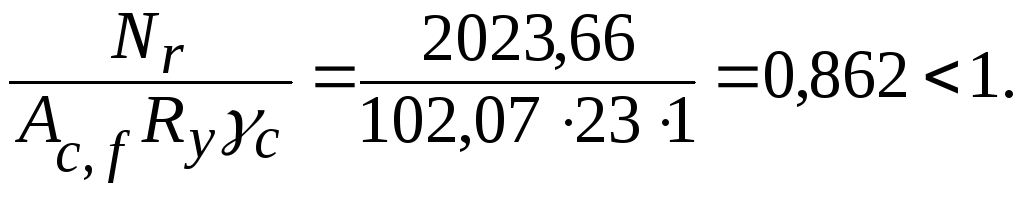
The strength of the belt at the mounting joint is provided.
Four-hole weakening ( n as \u003d 4) in the extreme row
A dn = n as n n dt nf \u003d 4 · 2 · 2,6 · 1,4 \u003d 29,12 cm 2.
Net cross-sectional area
Conditional area
A c , n = 1,18A n , nf \u003d 1.18 ∙ 89.88 \u003d 106.06 cm 2.
We check the strength of the pads:
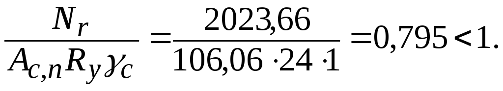
Durability of linings is provided.
Lining thickness increases if necessary t nf .
5.11. Bearing and mating beams
According to the design basis, two types of conjugations of beams with columns are distinguished: bearing from above (articulated) and abutment on the side (articulated or rigid). Side abutment is performed as flange connection either using a table. The articulated conjugation transmits only the reference reaction, while the rigid one, in addition to the reaction, also transfers the reference moment. The supporting table, made from an unequal corner or a thick sheet, perceives all the supporting pressure of the beam transmitted to the column through the seams. Seams are calculated for a force equal to the support reaction of the beam, increased by 30%.
When floor-to-floor conjugation, flooring beams or auxiliary beams are laid on top of the main beam, the design position of which is fixed on the compressed belt of the main beam with bolts or welds of minimum dimensions (calculation is not required) (Fig. 5.15, a) This method of pairing beams requires a large construction height of the beam cell. To increase the construction height of the main beam, it is necessary to apply the mating of the beams at the same level of the upper belts or with a lower location of the upper belts of the secondary beams.

Fig. 5.13.Articulated Beams:
a- floor; b- at one level; in- low
One of the options for joining the beams at one level can be performed according to the scheme of adjacency of the floor beams or secondary beams to the main beam from the side through stiffeners, which strengthen the wall of the main beam from stability loss. In this case, it is necessary to assign the step of the ribs so that they fall under each beam.
To ensure a tight abutment of the wall of the flooring beam to the ribs
it is necessary to cut its shelves and part of the wall (Fig. 5.15, b) This cutout weakens the beam section; the number of bolts that can be placed on the beam wall is limited. With reduced conjugation, a short from the corner is welded to the end of the auxiliary beam, through which the main beam is bolted to the stiffener.
In practice, the calculation of the bolts is performed on the support reaction of the auxiliary beam, increased in order to increase reliability by 20%, taking into account the uneven involvement of the bolts in the work due to some pinching in the connection.
As an example, we calculate the pairing of a flooring beam made of a rolling I-beam I27, with the main one at the same level (see clause 4.1.2). Belt thickness t ′ \u003d 9.8 mm, wall thickness t w ′ \u003d 6 mm, radius of internal rounding R \u003d 11 mm.
Dimensions of stiffener: width b r \u003d 75 mm, thickness t r \u003d 6 mm.
Determine the estimated force:
F b = 1,2Q max \u003d 1.2 · 57.57 \u003d 69.08 kN.
Fastening is carried out with bolts of normal accuracy of class 4.6 diameter d \u003d 16 mm (16 to 24 mm recommended). Estimated cross-sectional area of \u200b\u200bthe bolt A\u003d 2.01 cm 2 (see table. 3.11). Bolt holes d about =d + 3 \u003d 19 mm.
Design resistance to shear bolt R bs \u003d 15 kN / cm 2 (see tab. 3.9). Estimated crush resistance elements R b r \u003d 50 kN / cm 2 with a thickness of 4 to 10 mm s R un \u003d 38 kN / cm 2 connected by bolts made of steel of class C255 (see table 3.10).
Estimated wall height (Fig. 5.16)
h o = h –a 1 –a 2 \u003d 270 - 35 - 20.8 \u003d 214.2 mm, take 210 mm,
where a 1 =t ′ +R \u003d 9.8 + 11 \u003d 20.8 mm< (t + 10) \u003d 25 + 10 \u003d 35 mm, accept a 1 \u003d 35 mm; a 2 =t ′ +R \u003d 20.8 mm.
Distances between the centers of the bolts (see table. 3.8):
the minimum
from min \u003d 2.5 d about \u003d 2.5 ∙ 19 \u003d 47.5 mm, take 50 mm;
maximum
from max \u003d 8 d about \u003d 8 ∙ 19 \u003d 152 mm or
from max \u003d 12 t min \u003d 12 ∙ 6 \u003d 72 mm, take 70 mm.
Minimum distance from center of bolt to edge of element along force
a= 2d about \u003d 2 ∙ 19 \u003d 38 mm, take 40 mm.
Determine the binding of bolts to the axis of the main beam:
b about =t w /2 +k f + 2d about +10 \u003d 12/2 +4 + 2 ∙ 19 + 10 \u003d 58 mm.

Fig. 5.16.Attaching a floor beam to a rib
The width of the ribs for attaching the flooring beam should be:
b r , min \u003d b about –t w /2 + 2d about \u003d 58 - 12/2 + 2 ∙ 19 \u003d 90 mm\u003e b r \u003d 75 mm.
Take the width of the stiffener. b r \u003d 90 mm
The thickness of the ribs is determined from the condition of its stability:
accept t r \u003d 7 mm
Design effort N b that can be perceived with a single bolt:
- when cutting
N bs =R bs γ b An s \u003d 15 · 0.9 · 2.01 \u003d \u003d 27.14 kN,
where γ b \u003d 0.9 - coefficient of working conditions for many bolted connection when working on shear and crushing (see table. 3.13);
n s \u003d 1 is the number of design slices of one bolt;
- when wrinkled
N b r =R b r γ b d∑ t\u003d 46.5 · 0.9 · 1.6 · 0.6 \u003d 40.18 kN,
where ∑ t = t w \u003d 6 mm - the smallest total thickness of the elements crumpled in one direction ( t w or t r).
Number of bolts required
N=F b /(N b , min γ c) \u003d 69.08 / (27.14 · 1) \u003d 2.55.
Take 3 bolts in steps from= (h o – 2a) / 2 \u003d (210 - 2 · 40) / 2 \u003d 65 mm, which is more from min \u003d 50 mm and less from max \u003d 70 mm.
Net area of \u200b\u200bwall in section weakened by bolt holes
A n = h o t w ′ – nd about t w ′ \u003d 21 · 0.6 - 3 · 1.9 · 0.6 \u003d 9.18 mm.
Check the strength of the wall:
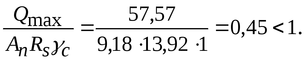
When attaching the secondary beam to the rib through the shorty, the welds that attach it to the end of the beam should be calculated for the joint action Q max and M = Q max l, here l - the distance from the axis of the bolted connection to the considered fillet welds. The calculation is made on the weld metal or on the metal of the fusion boundary:

GOST 24379.0-2012
Group G31
INTERSTATE STANDARD
BOLTS FUNDAMENTAL
General specifications
Foundation bolts. General specifications
ISS 21.060.10
Date of introduction 2013-07-01
Foreword
Goals, basic principles and the basic procedure for carrying out work on interstate standardization are established by GOST 1.0-92 "Interstate system of standardization. Main provisions" and MSN 1.01-01-2009 * "System of interstate normative documents in construction. Key Points
________________
* The document is not provided. For more information, click here. - Note by the manufacturer of the database.
Standard Information
1 DEVELOPED by Closed Joint-Stock Company “Central Order of the Red Banner of Labor Research and Design Institute of Building Metal Structures named after N.P. Melnikov" (ZAO TsNIIPSK named after Melnikov)
2 INTRODUCED by the Technical Committee for Standardization TC 465 "Construction"
3 ADOPTED by the Interstate Scientific and Technical Commission for Standardization, Technical Regulation and Conformity Assessment in Construction (MNTKS) (Minutes No. 40 of June 4, 2012
For the adoption of the standard voted:
Short name of the country | The abbreviated name of the state construction management body |
|
Belarus | Ministry of Architecture and Construction |
|
Kyrgyzstan | Gosstroy |
|
Russian Federation | Rosstandart |
|
Uzbekistan | Uzstandard |
(Amendment. IMS N 4-2016).
4 Order of the Federal Agency for technical regulation and metrology dated November 29, 2012 N 1851-st interstate standard GOST 24379.0-2012 was put into effect as a national standard Russian Federation since July 1, 2013
5 REPLACEMENT GOST 24379.0-80
Amendment published in IMS N 4, 2016
Amendment made by database manufacturer
Information on amendments to this standard is published in the annually published information index " National standards", and the text of changes and amendments is in the monthly published information index" National Standards. "In case of revision (replacement) or cancellation of this standard, a corresponding notice will be published in the monthly published information index" National Standards. "The relevant information, notification and texts are also posted in the public information system - on the official website of the national standardization body of the Russian Federation on the Internet
1 area of \u200b\u200buse
1 area of \u200b\u200buse
This standard applies to foundation bolts (hereinafter referred to as bolts) with a thread diameter of 12 to 48 mm for climate region I according to GOST 16350 and 12 to 140 mm for other climatic regions intended for fastening and fixing building structures or equipment.
2 Normative references
This standard uses normative references to the following interstate standards:
GOST 2.601-2006 Unified system for design documentation. Operational documents
GOST 515-77 Packaging paper tar and tar. Technical specifications
GOST 535-2005 Long products and shapes from carbon steel of ordinary quality. General specifications
GOST 977-80 * Steel castings. General specifications
________________
* Probably an original error. It should be read: GOST 977-88, hereinafter. - Note by the manufacturer of the database.
GOST 1050-88, long products, calibrated, with a special surface finish of high-quality carbon structural steel. General specifications
GOST 1412-85 Lamellar graphite iron for castings. Stamps
GOST 1759.0-87 * Bolts, screws, studs and nuts. Technical specifications
_______________
GOST R ISO 898-1-2011, GOST R 52628-2006 (ISO 898-2: 1999, ISO 898-6: 1994).
GOST 1759.1-82 * Bolts, screws, studs, nuts and screws. Tolerances, methods for controlling the size and deviation of the shape and location of surfaces
_______________
GOST R ISO 4759-1-2009.
GOST 1759.2-82 * Bolts, screws and studs. Surface defects and inspection methods
_______________
* GOST R ISO 6157-1-2009, GOST R ISO 898-1-2011 are valid in the territory of the Russian Federation.
GOST 1759.4-87 * Bolts, screws and studs. Mechanical properties and test methods
_______________
* GOST R ISO 898-1-2011 is valid in the territory of the Russian Federation.
GOST 5915-70 Nuts hexagonal accuracy class B. Design and dimensions
GOST 8017-74 Varnish BT-99. Technical specifications
GOST 10605-94 (ISO 4032-86) Hexagonal nuts with thread diameter over 48 mm, accuracy class B. Specifications
GOST 10705-80 Electric-welded steel pipes. Technical specifications
GOST 10706-76 Electric-welded steel pipes. Technical requirements
GOST 15150-69 Machines, devices and other technical products for various climatic regions. Categories, operating conditions, storage and transportation regarding the impact of climatic environmental factors
GOST 16350-80 Climate of the USSR. Zoning and statistical parameters of climatic factors for technical purposes
GOST 17769-83 * Fasteners. Acceptance rules
_______________
* GOST R ISO 3269-2009 is valid in the territory of the Russian Federation.
GOST 18160-72 Fasteners. Packaging. Marking. Transportation and storage
GOST 19281-89 Rolled steel of increased strength. General specifications
GOST 19537-83 Cannon grease. Technical specifications
GOST 24379.1-80 * Foundation bolts. Construction and dimensions
________________
* The document is not valid in the territory of the Russian Federation. GOST 24379.1-2012 is valid, hereinafter. - Note by the manufacturer of the database.
GOST 24705-2004 Basic norms of interchangeability. Thread metric. Main dimensions
GOST 27772-88 Hire for construction steel structures. General specifications
Note - When using this standard, it is advisable to check the validity of reference standards in the territory of the state according to the corresponding standards index, compiled as of January 1 of the current year, and according to the corresponding monthly published information signs published in the current year. If the reference standard is replaced (changed), then when using this standard should be guided by the replacement (modified) standard. If the reference standard is canceled without replacement, the provision in which the reference to it is given applies to the extent not affecting this reference.
3 Terms and definitions
In this standard, the terms used in accordance with GOST 24379.1, as well as the following terms with the corresponding definitions, are applied:
3.1 foundation bolt: A fastener in the form of a rod with a threaded part at one end and a special device holding the foundation bolt inside the foundation, designed for fastening and fixing building structures or equipment.
3.2 fastener: A part or assembly unit in a foundation bolt.
3.3 detail: Product that does not have components.
3.4 assembly unit: Set of fasteners.
3.5 product: A part or assembly unit manufactured at an enterprise (result of a manufacturing process).
3.6 batch of products: Fasteners made of the material of one heat, one diameter, one length and one type of size *, heat-treated in one mode and having one symbol.
________________
* The text of the document corresponds to the original. - Note by the manufacturer of the database.
3.7 batch of products: Fasteners made of the material of the same melt, one diameter, one length and one size, heat-treated in one mode and having one designation.
3.8 estimated cross-sectional area of \u200b\u200bthe stud: The cross-sectional area of \u200b\u200bthe threaded portion of the net.
4 Classification
4.1 Bolts are classified by:
- constructive performance;
- installation method in the foundation;
- the method of fixing the foundation in concrete;
- operating conditions.
4.2 By design, the bolts are divided into types (see GOST 24379.1):
- curved;
- with an anchor plate;
- compound;
- removable;
- direct;
- with a conical end.
4.3 According to the method of installation in the foundation, the bolts are divided into foundations installed before concreting and installed on finished foundations in wells or boreholes.
4.3.1 The bolts installed before concreting the foundations include:
- curved (type 1, version 1);
- with an anchor plate (type 2);
- compound (type 3);
- removable (type 4).
Note - When installing removable bolts in the foundation array, only anchor fittings are laid, and the stud is installed freely in the pipe after the foundation is installed.
4.3.2 The bolts installed on the finished foundations in wells or wells include:
- curved (type 1, version 2);
- straight lines (type 5);
- with conical end (type 6).
Note - Bolts of type 1, version 3, are installed in wells previously provided in the foundations, and bolts of types 5 and 6 - in wells drilled in the finished foundations with a mechanized tool.
4.4 According to the method of fixing in the foundation concrete, the bolts are divided into:
- fixed by direct interaction of the elements (studs or anchor plates) of bolts with concrete foundations (types 1-4);
- fixed with epoxy or siloxane glue, as well as cement-sand mixtures (types 5 and 6, versions 2 and 3), fixed with expandable collets (type 6, version 1).
4.5 According to operating conditions, the bolts are divided into design and structural.
4.5.1. Design bolts include bolts that absorb loads arising from the operation of building structures or equipment.
4.5.2. Structural bolts include bolts provided for fastening building structures and equipment, the stability of which against tipping or shear is ensured by the own mass of structures or equipment.
Structural bolts are intended for straightening of building structures and equipment during their installation and to ensure stable operation of structures and equipment during operation, as well as to prevent their accidental displacements.
5 Technical requirements
5.1 Requirements for raw materials
5.1.1 Bolts shall be manufactured in accordance with the requirements of this standard and GOST 24379.1.
5.1.2 Steel grades of studs of design bolts depending on the climatic areas of construction should be taken according to table 1.
Table 1
steel grade | Normative document | |||
II, II, etc. | ||||
St3ps, St3sp | ||||
For fastening building structures and equipment. For bolts with a diameter up to 24 mm incl. For bolts with a diameter up to 48 mm incl. For bolts with a diameter of 56 mm and more; for smaller diameters - with a feasibility study. Only for structural bolts. Note - The “+” sign means that the steel category and requirements for it should not be indicated in the project; the “-” sign means that this brand should not be accepted in the indicated climatic region. |
||||
5.1.2.1 Bolt studs may be made from steels of other grades whose mechanical properties are not lower than the properties of steels of grades specified in table 1.
5.1.3 Stud bolts in all climatic regions may be made of steel grade St3kp2 according to GOST 535.
5.1.3.1 Steel grade of structural bolt studs, if the latter are to be checked for seismic effects and impacts arising from the emergency operation of the equipment, should be assigned as for stud bolts (see table 1).
5.1.4 The calculated cross-sectional area of \u200b\u200bthe net stud, depending on the nominal diameter of the thread, shall be taken according to Table A.1 of Appendix A.
5.1.5 Nuts and bolt couplings should be made of steel of the same grades as studs. Suitable steel of category 2 may be used.
5.1.6 Washers and plugs should be made of steel grade 20 according to GOST 1050 or grade C235 according to GOST 27772; bushings - made of carbon steel grade St3kp2 according to GOST 535; collets and pipes - from any grade of steel of group B in accordance with GOST 10705 and GOST 10706.
5.1.7 Cast anchor plates for type 2 bolts, version 3, shall be made of gray cast iron of grade СЧ 15 in accordance with GOST 1412, and for type 4 bolts, version 2, from steel of grade 25L, satisfying the requirements for casting group II in accordance with GOST 977.
5.1.8 By agreement between the consumer and the manufacturer, it is allowed to manufacture studs with an increased length of the threaded part.
5.1.9 The appearance of the studs and nuts shall comply with the requirements of GOST 1759.0.
5.2 Completeness
5.2.1 Bolts must be supplied by the manufacturer in full in accordance with Figure 1 of GOST 24379.1.
5.2.2 The composition of the bolt kit shall be as specified in table 2.
table 2
Bolt type | Execution | Name of bolt | Parts and Assembly Units | ||||||||||||||||||||||||||||||||||
Curved bolts | 1 Stud (item 1) | ||||||||||||||||||||||||||||||||||||
2 washer | |||||||||||||||||||||||||||||||||||||
1 Stud (key 2) | |||||||||||||||||||||||||||||||||||||
2 washer | |||||||||||||||||||||||||||||||||||||
Anchor Bolts | 1 Stud (key 3) | ||||||||||||||||||||||||||||||||||||
2 Anchor plate (item 11) | |||||||||||||||||||||||||||||||||||||
3 washer | |||||||||||||||||||||||||||||||||||||
1 Stud (key 4) | |||||||||||||||||||||||||||||||||||||
2 Anchor plate (item 11) | |||||||||||||||||||||||||||||||||||||
3 washer | |||||||||||||||||||||||||||||||||||||
1 Stud (key 4) | |||||||||||||||||||||||||||||||||||||
2 Anchor plate (pos. 13) | |||||||||||||||||||||||||||||||||||||
3 washer | |||||||||||||||||||||||||||||||||||||
Composite bolts | 1 Stud (key 3) | ||||||||||||||||||||||||||||||||||||
2 Stud (key 5) | |||||||||||||||||||||||||||||||||||||
3 Coupling (key 13) | |||||||||||||||||||||||||||||||||||||
4 Anchor plate (item 11) | |||||||||||||||||||||||||||||||||||||
5 washer | |||||||||||||||||||||||||||||||||||||
1 Stud (key 4) | |||||||||||||||||||||||||||||||||||||
2 Stud (key 5) | |||||||||||||||||||||||||||||||||||||
3 Coupling (key 13) | |||||||||||||||||||||||||||||||||||||
4 Anchor plate (item 11) | |||||||||||||||||||||||||||||||||||||
5 washer | |||||||||||||||||||||||||||||||||||||
Removable bolts | 1 Stud (key 5) | ||||||||||||||||||||||||||||||||||||
2 Anchor fittings (pos. 14, execution 1) | |||||||||||||||||||||||||||||||||||||
1 Stud (key 6) | |||||||||||||||||||||||||||||||||||||
2 Anchor fittings (pos. 14, version 2) | |||||||||||||||||||||||||||||||||||||
3 washer | |||||||||||||||||||||||||||||||||||||
1 Stud (key 6) | |||||||||||||||||||||||||||||||||||||
2 Anchor fittings (pos. 14, version 3) | |||||||||||||||||||||||||||||||||||||
3 washer | |||||||||||||||||||||||||||||||||||||
Straight bolts | 1 Stud (key 7) | ||||||||||||||||||||||||||||||||||||
2 washer | |||||||||||||||||||||||||||||||||||||
Tapered End Bolts | 1 Stud (key 8) | ||||||||||||||||||||||||||||||||||||
2 Extension collet (key 15) | |||||||||||||||||||||||||||||||||||||
1 Stud (key 9) | |||||||||||||||||||||||||||||||||||||
2 Conical sleeve (pos. 16) | |||||||||||||||||||||||||||||||||||||
1 Stud (key 10) | |||||||||||||||||||||||||||||||||||||
2 Washer 5.2.3 It is allowed, by agreement between the consumer and the manufacturer, to deliver the bolts separately for parts or assembly units. 5.3 Marking5.3.1 A mark with the designation of the nominal diameter of the thread, mm, and length, see, for example, should be applied to the end of the studs. 5.3.2 On anchor reinforcement, the mark shall be applied on the outer surface of the pipe in the middle of its length. The mark should indicate the nominal diameter of the stud thread, mm, and the length of the pipe, cm, for example. 5.3.3 On anchor plates, the mark shall be applied on the plane of the plate. The mark shall indicate the nominal diameter of the stud thread and the size of the square plate or the outer diameter of the round plate, mm, for example, or. 5.3.4. On couplings, tapered bushings and collets, the mark shall be applied on the outer surface of the product. The mark should indicate the nominal diameter of the stud thread, mm, for which the product is intended, for example 20. 5.3.5 The rest of the marking requirements are in accordance with GOST 1759.0. 5.4 Packaging5.4.1 Before packing, the threaded parts of the bolts must be coated with PVC grease in accordance with GOST 19537 and wrapped in paper in accordance with GOST 515. 5.4.2 Other rules for packaging products and marking of shipping containers - in accordance with GOST 18160. 6 Acceptance rules6.1 Bolts for checking their compliance with the requirements of this standard and GOST 24379.1 shall be adopted by the technical control of the manufacturer. 6.2. Bolt acceptance shall be carried out in batches. 6.3 To control the bolts for compliance with the requirements of this standard and GOST 24379.1, three samples are taken from the batch. 6.4 If, when checking selected bolts, at least one bolt does not meet the requirements of this standard or GOST 24379.1, double the number of bolts from the same batch should be selected and re-checked. In case of unsatisfactory results of the re-inspection, the batch is rejected. 6.5 The rules for the acceptance of bolts in appearance and size, depending on the volume of the batch, must comply with the requirements of GOST 17769. 6.6 A batch of products is considered accepted if, during verification, compliance of all bolt parameters with the requirements of this standard and GOST 24379.1 is established. 6.7. The consumer has the right to control the quality of the bolts, while observing the acceptance rules and applying the control methods established by this standard. 6.8. At the request of the consumer, the bolt studs shall be tested for tensile, tensile and toughness. 6.9 The results of the acceptance inspection of the bolts must be documented in an act or protocol in the prescribed manner. 6.10 Each batch of products must be provided with a passport in accordance with GOST 2.601, which must indicate: 7 Control Methods7.1. The mechanical properties of the bolts shall satisfy the relevant requirements of the standards for the materials from which they are made. 7.2 Control of thread, deviations of linear dimensions, shape and location of surfaces of parts from nominal, as well as surface roughness should be carried out in accordance with GOST 1759.1 and GOST 1759.2. 7.3 Dimensions, not limited by maximum deviations, are not controlled, their observance is guaranteed by the technological process. 7.4 The test for tensile, tensile and impact strength of the studs should be carried out according to the method of GOST 1759.4. Three studs from a batch are tested. 7.5. The appearance of the bolts and their parts is checked visually without the use of magnifying devices. 8 Transport and storage8.1 Transportation of bolts and their parts is allowed by any mode of transport. At the same time, reliable fastening and their safety from mechanical damage must be ensured. 8.2 Transportation of products in containers without packaging in containers is not allowed. 8.3 Bolts must be stored in warehouses sorted by type, design and size and must be protected from contamination. The air in the room must not contain impurities of aggressive gases that cause corrosion of the bolts. 8.4 The conditions for the transportation of foundation bolts (products) when exposed to climatic factors must comply with conditions 7, storage - conditions 2 according to GOST 15150. 9 Manufacturer's WarrantiesThe manufacturer guarantees that the bolts comply with the requirements of this standard, subject to the conditions of transportation and storage. Appendix A (informative). Estimated net cross-sectional area of \u200b\u200bstudsAppendix A
|


