Axial load on the bolt. Strength calculation of threaded connections
The use of a bolted method of connecting parts allows, if necessary, to disassemble the structure or mechanism and simplifies dismantling for repair or restoration work.
During the operation of the structure, the joints of the parts experience various types of loads, which must be taken into account when designing. Bolted joints can be subjected to loads directed along the axes of the bolts (tension-compression), radial (torsion), as well as loads directed in the plane perpendicular to the axis of the bolt. The latter, overcoming the frictional force provided by tightening the bolt-nut pair, can cause shear and shear deformation of the fastener (rivets, studs, pins, dowels, etc. are also affected by such forces).
Using a bolted connection, it is possible to secure several parts, which increases the number of possible cut planes, which is also necessarily taken into account when designing a structure.
In the derivation, some simplifications are allowed when depicting the effects experienced by the details, and the values \u200b\u200bof the acting forces are taken to be maximum, to ensure reliability.
CALCULATION FORMULAS FOR CONNECTIONS TESTING SHARED LOADS
The shear bolt is calculated taking into account several factors that affect the ability of the joint to resist the forces acting on the parts being joined. These factors are:
- roughness of parts;
- yield strengths of materials;
- the difference between the diameters of the holes in the part and the bolt shaft;
- connection tightening force;
- transverse dimensions of the parts to be joined (thickness);
- the location of the holes relative to each other and the edges of the connected parts;
- the diameter of the bolt rod in its working part. The outer diameter of the thread is not taken into account, since it does not resist external forces;
- coefficients of friction of materials from which the connected parts are made.
Depending on the various conditions of the joints, the calculations for the slice are made according to different formulas.
The diameter of the bolt supplied with interference (without clearance) calculated on a slice by the formula:
D \u003d √4P / πt
D is the diameter of the bolt;
P is the transverse force acting on the bolt (in Newtons);
t is the permissible shear stress (in MPa), which depends on the material and is set according to the reference tables, usually 0.2-0.3 of the yield strength.
To prevent shear bolts with clearance , it is necessary to ensure the proper friction force between the parts, which is achieved by a certain bolt tightening force, and is calculated by the following formula:
Q \u003d P / f
P is the force transverse to the shear (shear) force created by tightening the bolt-nut pair;
f is the coefficient of friction. Depends on the materials from which the joined parts are made, on the cleanliness of the processing of the mating surfaces and the presence of lubricant, is set according to the directories.
Also tightening force
can be calculated by the formula:
Q \u003d πd²q / 4
d is the inner diameter of the thread of the bolt;
q is the maximum allowable tensile stress, MPa.
For several joints
the bolt is calculated on the tightening force:
Q \u003d P / fi
fi is the number of joints.
Tapered Bolts they are calculated in the same way as those installed with an interference fit, since the conical shape of the bolt head provides interface with the part without a gap.
When calculating a connection having several points of attachment of parts, the total load should be evenly distributed between the fasteners, or for the least loaded sections, the maximum shear forces should be taken.
Of course, the above formulas are of a general nature, not taking into account all the working conditions of the compound. The previously considered factors affecting the strength of the compound are introduced, if necessary, into these formulas in the form of additional coefficients obtained by calculation or empirically.
Moreover, when fastening parts with bolts, it is necessary to take into account the fact that unequal in absolute value and direction of force will act on different sections of the connection. To ensure the strength of the structure, a connection should be made taking into account the stress diagram, especially in cases not provided for by the standards.
Standards for bolted connections, developed taking into account the requirements for strength and reliability, establish the grades of steel used for the manufacture of fasteners, the dimensions of the fasteners and the distance between them. In addition, for bolts mounted with a gap, the dimensions of the holes for them are regulated.
So, for example, the requirements for those used in construction are established by the industry standard STO 0041-2004 “Steel construction structures. Bolted connections. Design and calculation. "
Standards provide for a wide range of sizes of fasteners - bolts, nuts, groove washers, which allows you to design structures without resorting to unnecessary calculations of new parts and their production. It is enough to take advantage of the already produced industry, making adjustments taking into account the margin of safety (as a rule, its coefficient is taken equal to 1.3 of the maximum load on the connection).
IMAGE OF BOLT COMPOUNDS ON DRAWINGS
When constructing threaded (including bolted) joints in the drawings, screw threads are depicted conditionally. This achieves simplicity and speed of execution of the drawings. Accepted conditional images are installed in accordance with GOST 2.315-68.
The external thread of the bolt on the outer diameter is conventionally indicated by a solid main line, on the inner diameter by a solid thin line. On the projections of a bolt formed by dissecting its plane perpendicular to the axis, the inner diameter is indicated by a thin line drawn on three quarters of a circle. The chamfer is not shown, only on the longitudinal section of the bolt. The distance between the thin and the main lines should not be greater than the thread pitch, but should not be less than 0.8 millimeters.
The internal thread on the nut is depicted vice versa - the main line along the inner diameter.
Cross-sectional and cross-sectional hatching is performed to a solid main line. When applying a bolted joint to the drawing, the dimensions of the bolt, nut and washer are made in accordance with their standard dimensions. That is, the sizes of standard fasteners are installed according to GOST on them.
Fail due to rupture of the rod along the thread, damage or destruction of the thread. Since the sizes of standard bolts, screws and studs meet the condition of their equal strength according to the specified criteria, the calculation is usually carried out according to one main criterion for operability - the strength of the cut part of the rod. From the calculation of the rod for strength, the nominal diameter of the thread of the bolt is determined. The length of the bolt is taken depending on the thickness of the parts to be joined. The remaining dimensions of the bolt, as well as the nuts, washers and nut locks, are taken depending on the diameter of the thread according to the relevant GOSTs.
Consider the calculation of bolts under static loading.
The bolt is loaded with axial tensile force.
The bolt is loaded with axial tensile force; its preliminary and subsequent tightening are absent (unstressed connection, Fig. 1).
This type of loading is relatively rare. Bolts in this case are usually under the influence of gravity. A threaded end of the load hook of a hoisting machine can serve as a typical example of this loading.
Fig. 1Bolt Strength Condition 
Where σ p - the calculated tensile stress in the cross section of the cut part of the bolt;
F - force stretching the bolt;
d 1 - the inner diameter of the thread of the bolt;
[σ p] - permissible tensile stress of the bolt.
Formula (1) is used in the verification calculation of the bolt. From it follows the dependence for the design calculation of the bolt 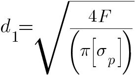
or 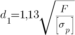
The bolt experiences tensile and torsion due to tightening.
The torque occurring in the dangerous cross section of the bolt is equal to the moment T in thread defined by the formula 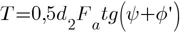
Only for set screws when determining the moment twisting the rods, the moment of friction at the end should be taken into account.
Equivalent stress in a bolt, in a dangerous cross section of which a longitudinal force arises equal to the force F puffs and torque Tequal to the moment in the thread, we determine by the hypothesis of the energy of forming: 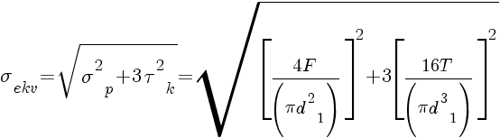
Where σ ekv - equivalent (reduced) voltage for the danger point of the bolt;
σ p - tensile stress in the cross section of the bolt;
τ k - the highest torsional stress arising at the points of the contour of the cross section of the bolt.
We substitute the value of torque from the formula into the formula
and take out the factor 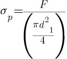
from under the root. Get 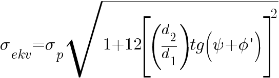
Taking for standard steel bolts with metric thread ψ \u003d 2 ° 30 ", d 2 / d 1 \u003d 1.2 and f \u003d 0.15 what corresponds ψ \u003d 8 ° 40 "finally get σ ekv ≈1.3σ p
Consequently, a bolt operating simultaneously in tension and torsion can only be calculated in tension by the allowable tensile stress reduced by 1.3 times, or by the design force increased by 1.3 times in comparison with the force stretching the bolt.
Thus, the design calculation of the bolt in this case is recommended to be performed according to the formula 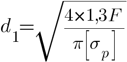
or 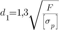
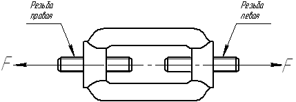 Fig. 2
The pre-tightened bolt is additionally loaded with an external axial tensile force; subsequent tightening of the bolt is absent or possible.
This type of loading is the most common, since most threaded connections require preliminary tightening of the bolts, which ensures tightness of the connection and the absence of mutual displacements of the joint parts that disrupt the operation of the connection. Bolts of this category include flanged, foundation, etc.
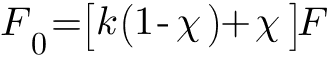
After pre-tightening the bolt by force F 3 the bolt is stretched, and the joint details are compressed. When acting on the bolt connection of an external sip F (Fig. 3) only part of it χ F additionally loads the bolt and the rest (1-χ ) F goes to partial unloading of joint parts from compression (Fig. 4). Coefficient χ taking into account the share of external load Fper bolt is called coefficient of external (main) load.
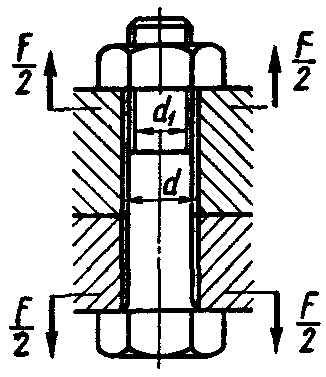 Fig. 3
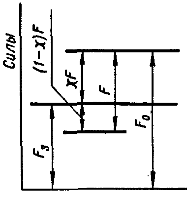 Fig. 4
Since the problem of the distribution of power F between the bolt and the joint is statically indefinable, then it is solved using the condition of compatibility of deformations. When acting on the connection of an external force F before the joint opens, the compression of the parts connected by a bolt decreases by as much as the bolt stretches, i.e. 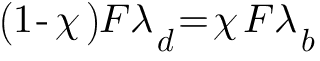
Where λ d - compliance coefficient of bolted parts;
λ b - the coefficient of compliance of the bolt, i.e., the elongation of the bolt under tension under the action of a force of 1 N. From the equation it follows that the coefficient of external load 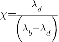
 Fig. 5
Bolt Compliance Ratio 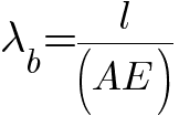
Where l - the length of the deformable part of the bolt rod, taken equal to the thickness of the parts to be compressed by the bolt;
A - cross-sectional area of \u200b\u200bthe bolt rod (for a stepped rod - the average reduced cross-sectional area);
E - the modulus of elasticity of the material of the bolt.
To determine the compliance coefficient λ b connected parts use the method proposed by prof. I.I.Bobarykov.
According to I.I. Bobarykov, the deformations of the parts to be joined extend to the so-called pressure cones (Fig. 6), the outer diameter of the smaller bases of which is, respectively, the outer diameter of the nut bearing surface (bolt head, spring washer, etc.), and the generators tilted at an angle α \u003d 45 °. Recent studies have found that the angle α<45° . Recommended to take tg α \u003d 0.5.
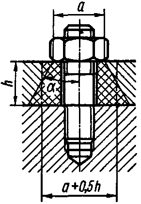 Fig. 6
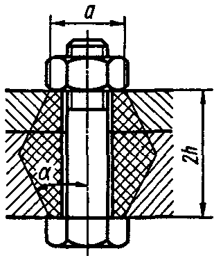 Fig. 7
To simplify the calculations, replace the cone with a cylinder whose outer diameter is equal to the average diameter of the cone. Compliance coefficient of connected parts 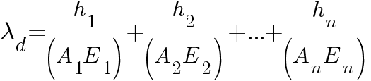
Where h 1, h 2, ..., h n - the thickness of the parts to be joined;
A 1, A 2, ..., A n - the cross-sectional area of \u200b\u200bthe pressure cones (cylinders) from the relevant parts;
E 1, E 2, ..., E n - the elastic moduli of the materials of these parts.
For the connection shown in (Fig. 6), 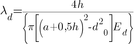
and for the connection shown in (Fig. 7), with the same materials of the parts to be joined 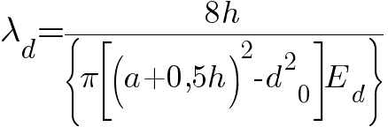
With a high coefficient of compliance λ b bolt and low ductility λ d connected parts external load factor χ small and almost all external force F goes to unload the joint. With a low coefficient of compliance λ b bolts and high ductility λ d parts to be joined, for example when using a thick elastic strip at the joint, most of the external force F transmitted to the bolt. In the absence of elastic gaskets, the coefficient of external load χ =0,2...0,3 . In the presence of elastic gaskets, the coefficient i\u003e χ is of great importance and may be close to unity.
The condition of the impossibility of opening the joint ![]()
Where to
- bolt tightening coefficient taking into account the force F b pre-tightening the bolt; in joints without gaskets at constant external load to=1,25...2
at variable external load to=2...4
. According to tightness conditions in joints with gaskets, the coefficient to
It is recommended to increase to 5, and sometimes more.
From the above it follows that tensile force F 0acting on the bolt after pre-tightening and applying external force F (see fig. 4)
or
In the absence of subsequent tightening, the bolt is calculated taking into account the torque of the preliminary tightening according to the design force, see the formula 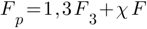
or 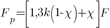
When calculated using the previous force formulas F 0 and F p external load factor χ are set within the limits indicated above. After calculating the bolt, it is recommended to calculate the value χ and compare it with the previously accepted value. If between a previously accepted value χ and its calculated value is a big difference, you should take the value χ closer to the calculated value, and then re-calculate the bolt.
The design calculation of the bolt in the absence of subsequent tightening is carried out according to the formula 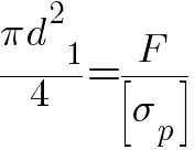
where from 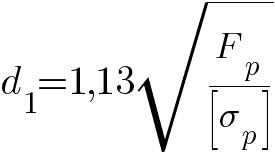
The design calculation of the bolt, for which subsequent tightening is possible, is carried out taking into account the torque caused by this tightening, according to the design force equal to 1,3F 0
where from 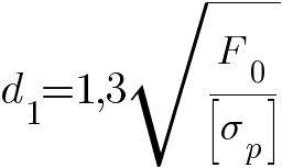
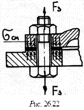
A bolt mounted in a hole with a gap (Fig. 8) is loaded with a transverse force.
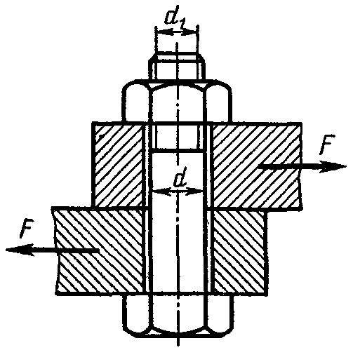 Fig. 8
In this case, the bolt is tightened with such a tightening force F 3so that the friction force resulting from this F ƒ at the interface of the parts to be joined was no less than the external shear force F. As a result, the bolt works in tension by force. F 3. The required bolt tightening force is determined from the condition 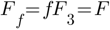
where from 
Where ƒ
- coefficient of friction between the connected parts; for cast iron and steel parts ƒ \u003d 0.15 ... 0.2.
The permissible stress depends on the material of the bolt and its diameter, since there is a danger with uncontrolled tightening that the bolts of small diameters can be tightened before any permanent deformation occurs in them. This causes difficulties in the design calculation, since it is not known what permissible voltage should be accepted. Therefore, the calculation is carried out either by the method of successive approximations, or use tabular data of the permissible tightening forces of the bolts, calculated taking into account the dependence [σ t] for bolt diameters, see table "Permissible tightening forces of bolts for uncontrolled tightening".
With controlled tightening (in large-scale and mass production), the safety factor of carbon steel bolts under static load [s] \u003d 1.3 ... 2.5; large values \u200b\u200bfor structures of increased responsibility or with low accuracy in determining the effective loads.
Permissible stress on the collapse of bolted joints when fastening steel parts 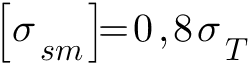
when fastening cast iron parts 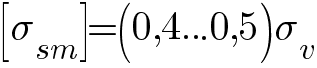
Where σ t - yield strength;
σ v - the tensile strength of the material of the parts to be joined.
Types of destruction of threaded fasteners: rupture of the rod along the thread or transition section at the head; damage or destruction of the thread (crushing and wear, shear, bending); damage to the head of the bolt (screw).
The sizes of standard bolts, screws and studs meet the condition of equal strength of all elements of the connection. Therefore, it is possible to be limited by calculation according to one basic criterion - the strength of the threaded part, and the sizes of screws, bolts and nuts can be taken according to the tables of the standard depending on the calculated thread diameter. The length of the bolt, screw and stud is selected depending on the thickness of the parts to be joined.
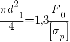
Consider the calculation of strength threaded connections at constant load.
The bolt is loaded with an external force F (a bolt without preliminary tightening), for example, a cut section of a hook for hanging a load. The hook section weakened by cutting is dangerous (Fig. 26.21). From the condition of tensile strength
![]() (26.22)
(26.22)
 (26.23)
where \u003d 0.6– permissible tensile stress of a carbon steel bolt.
The bolt is tightened with a tightening force F s, and there is no external load (unloaded covers, brackets, etc.). The bolt shaft experiences the combined action of tension and torsion, i.e. stretched out axial force F 3 from tightening the bolt and is twisted by a moment equal to the moment of friction in the thread T p (formula (26.16)). The strength of such bolts (Fig. 26.22) is determined by the equivalent stress
![]() (26.24)
(26.24)
where is the tensile stress, determined by the formula (26.22) at F \u003d F s; - torsional stress, ![]() - the required safety factor of the bolt, taken depending on the material
- the required safety factor of the bolt, taken depending on the material
the bolt, the nature of the load and the diameter of the bolt.
For standard metric threads, that is, the calculation of the bolt for the combined action of tension and torsion can be replaced by the calculation of tension, but with an increase of 1.3 times the force F p. For metric threads
 (26.25)
The estimated diameter of the thread of the bolt is determined by the formula (26.23), taking
Bolted connection loaded with forces that shift parts in the joint. The condition for the reliability of the connection is the absence of shear of parts at the joint.
In connection with the gap (Fig. 26.23 a), the bolt is installed with a preliminary tightening. The external force F is not directly transmitted to the bolt; therefore, it is calculated for tension along
tightening force F c.
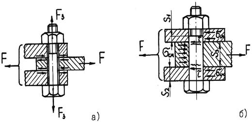
Rice. 26.23
To avoid shear of parts in the presence of a gap, the friction force on the surfaces of the joint should be no less than the external shear force F:
![]() (26.26)
(26.26)
where i - the number of joints in the connection; f -coefficient of friction; K - safety factor ( TO \u003d 1.3 - 1.5 for static and TO \u003d\u003d 1.8 - 2.0 at variable load); Z is the number of bolts in the joint.
The bolt in this case is calculated by the tightening force
 (26.27)
When installing the bolt without a gap (Fig. 26.23 b), preliminary tightening is not required. The bolt experiences shear and crushing. Bolt stem count on
cut, and with fine details - and crushing. Strength conditions:
![]() (26.28)
(26.28)
where is, respectively, the calculated and permissible stress for the material of the bolt per shear, \u003d (0.2 - 0.3); d o - the diameter of the uncut part of the bolt; –Respectively, the calculated and lowest permissible crushing stresses (for the material of the bolt or part), \u003d (0.8 - 1.0); S–smallest part thickness.
The bolt is tightened, and the external load tends to open the joint (bolts for attaching the covers of reservoirs for gas and liquid, loaded with pressure above atmospheric, fastening cylinders, pumps, beds to foundations, etc.). Tightening the bolts should ensure the tightness of the connection or non-opening of the joint (to prevent the appearance of a gap) under load. This problem is solved taking into account the deformation of the connection details.
The external load (R is the resultant load; Z is the number of bolts) causes the bolt to elongate (Fig. 26.24), and the deformation of the parts decreases by the same amount. The load on the part side of the bolt will also decrease. That is why it is believed that the bolt perceives a part of the external load.
where is the external load coefficient showing how much of the external load is perceived by the bolt (takes into account the compliance of the bolt and the parts to be joined).
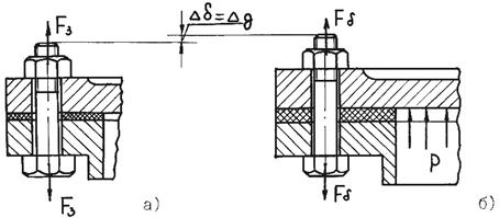
The value is determined by the condition of equality of additional deformations of the bolt and parts. From the condition of preserving the joint density of the parts to be joined (impossibility of a gap), take
![]() (26.31)
(26.31)
where K z - safety factor of preliminary tightening: at constant load K z \u003d 1.25 - 2.0; with the variable K s \u003d 2.5 - 4.
When calculating the strength, if subsequent tightening of the bolt is possible, it is calculated according to the design load F p taking into account torsion: ![]() (26.32)
(26.32)
Dimensions are for wheels with external teeth.


