Calculation of flange connections. Pipe flange connection: types and installation
In order to increase the reliability of threaded and flange connections must be applied modern methods engineering design. This article discusses the possibility of simplifying the rather complex task of calculating a flange bolt connection.
Simplification of the model and the task of calculating the flange bolt connection
Fig. 1. Bolt connection (a) and
its schematic approximation (b)
for calculations
In the simplest engineering calculation, a group (multi-bolt) connection (Fig. 1, a) is approximated by a set (in number) of conical bushings (Fig. 1, b) connected to each other by an absolutely rigid, non-deformable diaphragm having the shape of a part in plan. External loads are transferred to the bushings from the diaphragm.
The basis of the described calculation model is the following fact: when tightening maximum normal stresses (deformations) act at the points of the connected parts located next to the mounting hole in the flange (Fig. 2, a), forming the so-called pressure cone (shown in dashed lines in blue). The parts to be joined or their parts - flanges - undergo mainly compression deformations, working like rods of variable cross section under axial loading (Fig. 2, b). Contact of parts occurs along the annular platform - the base of the pressure cone.
It is assumed that under the influence of an external load, the main deformation also occurs within the described pressure cone, and the contact area (base of the cone) is independent of the load. This allows us to generalize the calculation model of the tightened joint to the case of simultaneous action of 1) tightening and 2) external loads.
The one-dimensional core model of the real compound, available in the works of Retscher, Bach, etc., is nevertheless sufficiently accurate for when the bending deformations of the flange parts to be joined are small, for example, the joining of machine cases, plates and beds with rigid bases. The results of numerous studies show that the described approximation is acceptable for compounds with thin, flexible bending flanges. In this case, the calculation satisfactorily corresponds to the experiment: 1) at sufficiently large tightening voltages σ 0 \u003d (0.5 ... 0.7) × σ t where σ t - yield strength of the material bolts, and 2) such an external load at which the joint opens slightly.
Connection calculation tasks consist of determining the forces in the bolt and the parts to be pulled together with the combined action of the tightening force and the external axial force .
Calculation of the connection with one fastener (bolt or stud)

Fig. 3. Force pattern in
tightened threaded connections.
Let us consider a connection with one fastener (Fig. 3, a), tightened by force F 0 and then loaded with an external force F= F Σ / z ( F Σ is the total force acting on the group connection with the number of bolts (or ), equal to z), and determine the load acting on the bolt (stud) using the above-described schematization of the connected parts in the form of bushings fastened by a diaphragm.
To solve the problem, we replace the attracted parts with bushings equivalent in flexibility, and apply an external load to the upper and lower ends of the bushings symmetrically with respect to the axis of the bolt (Fig. 4). Force F 0 is depicted conditionally; it arises due to the preliminary deformation of the bolt (stud) when tightening.

Fig. 4. Threaded force calculation circuits
flange connections with bolts or studs
The equilibrium equation of one of the bushings will take the form
where F b - additional force in the bolt arising under the action of an external force F. The force at the junction after the application of external force F marked F c.
Equation (1) contains two unknown forces F b and F c. To determine them, one should take into account the equation of compatibility of displacement flanges and bolts.
If you accept that δ - additional lengthening of the bolt under the action of an external load, then the total force in the bolt
where λ b - axial compliance of the bolt or stud, corresponding to its elongation under the action of a force of a single value; Δ b - bolt extension when tightening:
The shortening of the bushings due to the compatibility of movements will decrease by δ . The force at the junction after applying an external load:
where λ d is the axial compliance of the connected bushings, it is equal to the mutual approach of the supporting ends under the action of a compressive force of a single value.
Initial shortening of intermediate parts when loading
From equations (1) - (5) we obtain
Extra bolt force from external load
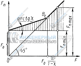
Fig. 5. Dependence of effort in
bolt F n from external load F.
Thus, in a tightened bolted connection, only a part of the external load is proportional to the coefficient χ perceived by a bolt. The other part of the external load, equal to 1 - χ , reduces the initial compression of parts, i.e.
The dependence of the total force in the bolt (stud) on the external load is shown in Fig. 5. For the connection, a sketch of which is shown in Fig. 6, similar dependences were experimentally obtained. The solid lines show the curves corresponding to the height of the profile irregularities. R z \u003d 0.4 ... 0.8 μm at the junction of the bushings, dashed - the same for R z \u003d 80 ... 160 μm.
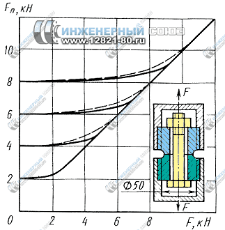
Fig. 6. The dependence of the force in the bolt F sweat
external and pretightening forces.
Equality (11) is valid until the beginning of the disclosure of the joint. Joint force after external force
| F c \u003d F 0 - F d \u003d F 0 - (1 - χ )F | (12) |
At F c \u003d 0 the joint will open (dot B with in fig. 5); with external load
F p \u003d F 0 / (1 - χ )
and full bolt force
F n \u003d F 0 + χ F p \u003d F p.
To prevent the joint from opening, the bolt (or other flange fastener) must be tightened
F 0 min ≥ (1 - χ )F.
Thus, the minimum tightening force flange connection determined by the external load and its design.
After the joint is opened, the external load is completely transferred to the bolt, which under alternating loading leads to the appearance of additional stresses of an impact nature. Therefore, the tightening force should be assigned so that at a given external load F the joint remained tight.
where α b t b and l b - coefficient of linear expansion, temperature and lengths of the mounting bolt or stud; α b t b and l b - the same for connected .
The total force acting on the bolt in this case,
average cycle voltage in this case
List of references
- Iosilevich G. B., Stroganov G. B., Sharlovsky Yu. V. Tightening and locking threaded connections.. - M.: Mechanical Engineering, 1985. - 224 c.
- Gould D., Mikich M. Contact areas and pressure distribution in bolted joints // Design and Engineering Technology. 1972. No. 3 ... - S. 99.
- Retscher F. Machine parts: in 2 volumes .. - M.: Gosmashmetizdat. 1933-1934
By accessing this page, you automatically accept
The reliability of any system depends on the reliability of the weakest link in the system. Welded joints of steel pipes are reliable and are used in most cases. But there are situations in which the use of a welded joint is impossible. Connecting various fittings, providing a collapsible connection, the possibility of prevention and repair of pipe fittings and working units of assemblies, connecting dissimilar pipes: cast iron-plastic, cast iron-steel, steel-plastic, steel-asbestos cement, plastic-asbestos cement and solving many more technological problems. To ensure the reliability and durability of the operation of such connections should be a flange connection. In general, the design of the flanges provides for a pair of flanges and a gasket and rings connected by bolts or studs.
To unify the products and the possibility of using these products in various countries of the world without additional processing, a clear classification of flange joints has been introduced. Sometimes the same flange in different classifications will have different designations.
The main classifications used in the world:
GOST - the standard adopted in the USSR, and operating in the post-Soviet space;
DIN - German standard in force in Europe;
ANSI / ASME is an American standard valid in the USA, Japan and Australia.
There are tables for the translation of standards that indicate which standard a particular flange meets.
For the manufacture of flanges using various materials:
cast iron;
malleable cast iron;
carbon steels;
stainless steels;
alloy steels;
polypropylene.
Polypropylene flanges have been widely used in the last decade. They are mainly used for mounting pressure-free systems, connecting PE pipes to metal, joining pipe fittings on which a flange mount is installed. They produce flanges, like metal, by casting or stamping.
The flanges are divided into types:
flat (GOST 12820-81);
collar (GOST 12821-81);
loose flanges on the welded ring (GOST 12822-80);
flanges for vessels and apparatuses (GOST 28759.2-90);
ring plug (GOST 12836-80).
Allowed the manufacture of square flanges that have a minimum of 4 holes for bolts or studs. Such flanges can be used on systems with a maximum pressure of not more than 4.0 MPa.
According to the nomenclature and, accordingly, GOST 12815-80, the flanges of valves and connecting parts of pipelines have nine main versions of the sealing surface:
spanish 1 - with a connecting protrusion, the most common version of the flanges, has a special connecting protrusion in the form of a chamfer at an angle of 45 °
Spanish 2 - similar in execution to the previous model, only the connecting protrusion goes at an angle of 90 °;
Spanish 3 - with a hollow on the inside and a protrusion on the outside at an angle of 45 °;
Spanish 4 - with a spike;
Spanish 5 - with a groove in the form of a circular selection;
Spanish 6 - under the lens gasket, a bevel is selected from the inside;
Spanish 7 - for laying an oval section, an annular selection in the form from the front side;
Spanish 8 - with a spike under the fluoroplastic gasket;
Spanish 9 - with a groove under the fluoroplastic gasket.
For flanges of vessels and apparatuses there are specific performance requirements indicated in GOST 28759.2-90, and for flat welded flanges - in GOST 28759.390
Design features of flanges
Flanges, like any pipe or stop valves, have several design features. When choosing and deciphering the designation of flanges, these features must be known.
Conditional pass
The conditional passage of the flange is the inner diameter of the pipe, fittings or valves on which the flange is welded. It is taken based only on the conditional passage of the pipe.
For flat welded flanges with a nominal bore of 100, 125, 150, the letter (A, B, C) is indicated depending on the design - the external diameter of the pipe depends on it, if the letter is not specified, the letter A is considered by default.
All geometric dimensions of the flange will depend on the conditional passage. The same flange with the same conditional passage can be made in two ways - row1 and row2. They are distinguished by different interaxal distances between the connecting holes, and also in some cases by different diameters of the connecting holes. By default, flanges are manufactured in row 2.
Pressure
An important property of a flange connection is the ability to maintain system pressure without leakage and system failure. This indicator is designated as conditional pressure. The conditional pressure indicator depends on the geometric dimensions of the flange, the material of manufacture, execution, and the gasket.
Important: When ordering flanges, remember that there are different pressure dimensions: in kgf / cm2, Pa (MPa), atm., Bar. Therefore, it is necessary to indicate exactly what pressure this product should be designed for.
Temperature
The working temperature of the liquid will become the temperature of the flange; note that the pressure and temperature parameters are interdependent. As the temperature rises, the maximum pressure under which the flange joint operates will drop. Dependence can be expressed by linear interpolation. Dependencies between the operating temperature and pressure for each flange are given in special tables and GOSTs.
Flange designation
Each type of flange has its own specific designation, we will consider each of them.
Flat Weld Flanges
Let us examine the designation of flat welded flanges as an example:
Flange 1-65-25 09G2S GOST 12821-80
Flat welded flange version 1 with nominal bore (DN) - 65 mm, designed for nominal pressure of 25 kgf / cm2, made of 09G2S steel in accordance with GOST 12821-80.
When choosing a flange for a fluoroplastic gasket after the number Du, indicate the letter F.
Collar Flanges
Flange 1-1000-100 Art. 12x18n10t GOST 12821-80
Designates a flange of execution 1, with a nominal bore of 1000, designed for a pressure of 100 kgf / cm2, made of steel 12x18n10t, which is structural stainless steel.
For square flanges, they additionally indicate in the name - a square flange.
As in flat flanges, when using a fluoroplastic gasket, the letter F.
Loose weld ring flanges
The designation of free flanges as well as flat flanges is slightly different. Since a welded ring is used in this product, the designation of the ring also includes the ring designation, for example:
Flange 50-6 ST20 GOST 12822-80
Ring 1-50-6 ST 35 GOST 12822-80
Here: 50 - nominal pass, nominal pressure 6kgf / cm2, the flange is made of steel st20, the ring is made of steel st35.
For conditional pass 100, 125, 150, you must also specify the letter (A, B, C), the default is A.
Gaskets for flange connections
Sealing a unit or joint under pressure, often in an aggressive environment, occupies an important place in the design of a flange joint.
Depending on the type of flange or yoke used, design, pressure, temperature, chemical properties media used as sealing gaskets:
KShch (7338-77) - technical acid-base rubber;
MB (7338-77) - oil and petrol resistant rubber;
T (7338-77) - heat-resistant technical rubber;
PON (481-80) - general purpose paronitis;
PMB (481-80) - oil and petrol resistant paronite;
Asbestos cardboard;
Ftoroplast-4.
Tightening flange joints
Tightening flange joints is the key to mounting a flange. To achieve maximum sealing, all parts must be accurate.
Element preparation
Flange surfaces clean and degrease, check for scratches, cavities and dents. Inspect for flange corrosion and the fasteners - bolts and nuts. Remove burrs from the thread, previously you can also “drive” each bolt and nut through the thread. Lubricate the threads of the bolt or stud. Prepare and install the gasket. Make sure that it is installed correctly, it should lie in the center.
Important: Do not use old gaskets if it is not possible to replace the gasket. It is possible to install several old gaskets.
Tightening sequence
Reliable and proper fixation of the flange will ensure the correct tightening order of the bolts. To do this, slightly shade the first bolt, select the next bolt from the opposite side, also tighten slightly. The third bolt that you tighten lags behind the first by a quarter of a turn (90 °) or close to this corner. The fourth is opposite the third. Continue the sequence until all bolts are tightened. When tightening flanges with a 4-bolt mount, use the technique - crosswise.
Torque
To get the most tight connection, the bolts must have the required tightening torque. The tension must be evenly distributed across the flange. During tightening, a tensile force opposite the tightening force of the joint acts on the bolt. With excessive tightening force, you can break the thread on the bolt or break the bolt itself.
To adjust the tightening force, different tightening techniques are used:
hydraulic tensioning mechanism;
hydraulic torque wrench;
pneumatic wrench;
manual torque wrench.
In extreme cases, you can use a puff by hand, but in a similar way it is better to work for a professional.
Regardless of the tightening method chosen, the force with which the nuts are tightened must meet the product specifications.
After installing the flange and starting the system in the first 24 hours of operation, a loss of tightening torque of up to 10% is possible. This is inherent in any bolted connection due to vibration, shrinkage of the gasket, and temperature changes.
After a day or two, additionally tighten the threaded connections to the specified moment, according to the specification.
__________________________________________________Introduction
Currently, the most versatile and convenient for the installation of steel building structures are bolted joints. Their application allows to obtain extremely high accuracy of the installation and to exclude the "human factor". Of bolted connections most effective are flange joints. Their use in various designs significantly increases labor productivity during installation and, accordingly, its speed. Also, flange connections are extremely convenient when repairing building structures; they allow you to quickly isolate one element and replace it with another.
To date, a fairly large number of scientists have studied flange joints and the features of their application. Among them, the work of V.V. Kalenova, V.M. Gorpinchenko, A.G. Soskina, O.I. Ganiza, Glauberman V. B. et al.
Basically, the above scientists conducted work on the study of the strength characteristics of flange joints. As a result of the research, recommendations were developed for the calculation, design, manufacture and installation of flange joints of steel building structures and chapter 27 of the design manual steel structures (to SNiP II-23-81 *). The manual and recommendations do not apply to flange connections:
Accepting alternating loads, as well as repeatedly acting mobile, vibrational or other types of loads with the number of cycles over 10 5 with a voltage asymmetry coefficient in the connected elements r \u003d s min / s max ³ 0.8;
Operated in a highly aggressive environment. These connections include flange joints of crane beams. Crane beams can be attributed to the elements of an open profile.
Chapter 1. The strength of the flange connections of elements of an open profile
The issue of the strength of flange joints of open profile elements was studied by Professor I. Grudev.
He developed a semi-empirical method of calculating the strength of flanged joints of elements of an open profile: I-beams, brands, corners. The assumptions are clearly formulated, which formed the basis of the problem being solved. A closed system of equations is compiled, including several adjustable parameters. The solution was obtained numerically, and the fitting parameters were determined from the experimental data. For convenience of using the technique, an approximation formula is proposed.
Determining the strength and durability of flanged joints of open profile elements: I-beams, Tauri and corners is the main undeveloped issue. In these compounds, the deformations of various bolts are substantially different, since the flange is deformed in a complex way and, in addition, the strength of the bolts themselves has a statistical spread and is determined by the density function of the probability of failure.
The study is based on the following provisions:
- All bolts have the same pre-tension.
- The bolts in the joint work unevenly, and by the nature of their work they are divided into two groups: bolts of the inner zone located in the corners of the section and more loaded, indicated below by the index B, and bolts of the outer zone with the index N.
- The outer zone is divided into elementary T-shaped joints.
- The latter are described by the beam model taking into account only geometric nonlinearity.
- The relationship between the forces in the bolts of the inner and outer zones is described by a piecewise linear function obtained by approximating the experimental data.
- If the destruction occurs by bolts, it has a probabilistic nature and is determined by the bearing capacity of the set of bolts of the inner zone.
- The bending of the bolt, the presence of holes for the bolts, the unevenness of the preliminary tension, the presence of external bending moments, leads to the need for the introduction of fitting parameters.
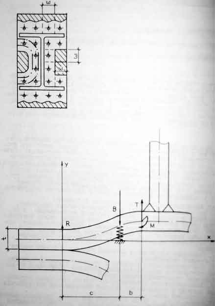
The forces arising in the flange connection in accordance with the beam model are described by the following relationships:
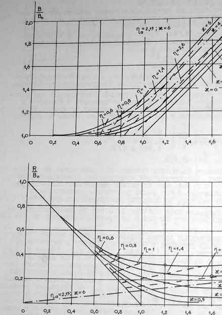
k is the stiffness of the bolt in tension taking into account contact displacements, is the value of the preliminary tension. The remaining notation is shown in Fig. 1.
Dimensionless quantities depending on and parameter are shown in Fig. 2. The dimensionless stiffness of the bolt can also be represented as
 (2)
(2)
Moreover, it is advisable to leave the parameter as adjustable, because to determine it theoretically is not possible.
The relationship between the forces in the bolts of the outer and inner zones depends on the dimensionless force applied to the flange and, within the limits of existing structures, weakly depends on other parameters. It is determined according to the experiment.
The destruction by bolts of flange joints operating in tension occurs, as the experiment shows, almost instantly, which indicates the avalanche nature of the destruction of bolts, and the avalanche usually begins after the destruction of the first bolt, i.e. the connection works according to the principle of the weakest element.
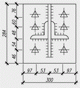
The analysis of experimental data shows that at the time of failure, the difference between the forces in the bolts of the inner and outer zones is in accordance with about 20-30%, because efforts in the bolts of the outer zone do not exceed 37t. At the same time, they cannot make a significant contribution to the total probability of destruction, therefore, the latter is determined solely by the strength of the more loaded bolts of the inner zone, and the bolts of the outer zone break at the final stage of avalanche destruction. For an I-section, and also for a T-section with an edge, four bolts belong to the inner zone.
Chapter 2. Stress-strain state of flange joints
Engineer A. Soskin conducted a study of the stress-strain state of flanged joints of open profile elements that perceive static tensile forces in order to obtain a relationship between the thickness of the flanges and the ratio of the forces perceived by the bolts of the internal and external zones from the action of external load.
Flange connections with high-strength bolts are the most effective in comparison with other types of mounting connections of elements of steel building structures. The effect is achieved mainly due to the almost full use of the bearing capacity of the bolts in tension, which ensures their minimum number in the joints and, as a result, significantly reduces the labor costs for installation of structures. In this regard, the calculation of bolts, based on assumptions that reflect their actual behavior, is of particular importance.
From the point of view of the behavior of bolts among the structural forms of flanged joints of tensile elements, one should distinguish between those in which the bolts are in the same conditions ("elementary" T-joints, FS of round and square pipes) and the joints in which the working conditions of the bolts are not the same (flange connections of elements of an open profile: paired and unpaired corners, brands, I-beams, etc.). Studies have shown that the behavior of the latter is very complex, characterized by geometric and physical nonlinearity.
In order to study the laws of the stress-strain state of such compounds, tests of prototypes of full-scale flange joints were carried out (Table 1):
- typical trusses a span of 24 meters with a lower belt of paired equal-angled corners 110x12, 125x8 and 140x12mm;
- wide-shelf brands 15sht4;
The material of the corners, brands, faoyok, stiffeners and flanges - steel with a design tensile strength at the yield strength of 225 to 400 MPa. Flanges of prototypes with a thickness of 20, 25 and 30 mm were welded to the connected elements without cutting edges, manually using electrodes of type E50A according to GOST 9467-75. Bolts high-strength M24 from steel 40X "Select" with a standard tensile strength of 1100 MPa. Prototypes were tested on a special bench, allowing to develop tensile forces in the connected elements up to 4000 kn. The measurement of relative strains was carried out by strain gauging using sensors with a base of 5, 10 and 20 mm. All samples were brought to failure, the nature of which was recorded.
The analysis of experimental data showed that the distribution of normal stresses in the sections of the connected elements located in the immediate vicinity of the flanges is almost uniform. At the same time, the efforts in the bolts and the bending stresses on the characteristic sections of the flanges of the tested joints develop unevenly.
In fig. Figure 3 presents the average diagram of the forces in the bolts of the T-4 sample, typical for experimental FS with the number of bolts 6 and more. Of the diagram shows that a much more intense increase in effort occurs in bolts No. 1,2,3,4 located on the flange sections of the inner zone - OT (see connection diagram - shaded area). The external load of the disclosure of the inner zone of the flanges Т Р в \u003d 1236 kN, of the outer zone (НЗ) - Т Р Н \u003d 1688 kN. The corresponding increase in effort in the VZ bolts relative to the pre-tension force V о в \u003d 216 kN was ΔВ в \u003d 29 kN. At the time of joint failure at T times \u003d 1962 kN, the force in the bolts \u003d 392 kN. For NC bolts, these values \u200b\u200bare equal: B 0 \u003d 216 kN, ΔB n \u003d 15 kN, B times \u003d 260 kN. The experimentally obtained efforts in the bolts, the corresponding external load values \u200b\u200band the data on the fracture pattern of the experimental FS are given in table. 2, From the table it follows that the revealed pattern of development of efforts in the T-4 bolts can be traced in other experimental compounds.
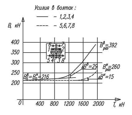 Fig. 3 Diagram of the efforts in the bolts of the experimental connection T-4
The disclosure of the flanges of the VZ occurs earlier than the NZ (T P in< Т Р Н), а усилия в болтах ВЗ — В в (после раскрытия фланцев) всегда больше В н. Причина этого заключается в различной жесткости внутренней и наружной зоны фланцев. Анализ напряженно-деформированного состояния показал, что изгибные напряжения во ВЗ фланцев развиваются заметно слабее, чем в НЗ, более жесткая на изгиб внутренняя зона фланцев передает на болты большую часть внешней нагрузки — Т в по сравнению с наружной, передающей на болты нагрузку Т н (Т = Т в + Т н). Но этой же причине рычажные усилия — R, действующие на болты ВЗ и НЗ также неодинаковы.
Note that the experimental values \u200b\u200bof stresses in dangerous sections of the flanges with a thickness t ≥ 20 mm and achievement of the calculated forces in the bolts - In p, did not exceed the values \u200b\u200bof the calculated resistance of the steel flanges to bending along the yield strength.
Table 1. The geometric parameters of the experimental compounds
|
Connection designation |
Connection diagram |
Section (mark) of a profile mmkhmm |
Flange thickness |
Weld leg |
Shaped thickness (ribs) |
 |
|||||
 |
|||||
 |
|||||
 |
|||||
Chapter 3. Fatigue strength of flange joints of tensile elements
The fatigue strength of flange joints of tensile structural elements was studied by V.V. Kalenov, A.G. Soskin, and V.V. Evdokimov. They presented the results of experimental studies of the cyclic durability of mounting flange joints of structural elements that perceive cyclically changing, tensile loads. The calculated fatigue curves of high-strength bolts and welded joints of flanges with a profile are obtained. It is shown that the cyclic durability of the joints should be determined by the amplitude of the nominal voltages. At the same time, the lowest durability value obtained for bolts or welded joints with various types of design and weld defects should be taken as the calculated one.
During operation, flange connections perceive both static and cyclic influences.
In one of the first studies on the characteristics of FS fatigue resistance, the results of tests of 12 double-byte T-shaped joints are presented. The fatigue curves of bolts A325 and A490, obtained with a pre-tension force of To - (0.7 + 0.8) Tu., Where Tu is the breaking stress of the bolts under tension, are obtained. It is concluded that the high durability of the bolts can be ensured by a high level. ceteris paribus leads to a significant decrease in the amplitude of the alternating stresses in the bolts. Fatigue studies are also provided. high strength bolts M22 type F9T and FIIT, operating as part of the FS. The experimental compounds were tested in series of 6 + 13 samples with the same geometric characteristics. It is shown that the durability of the bolt group largely depends on the value of the preliminary tension of the bolts. It should be noted that the tested bolts in mechanical properties and chemical composition differ significantly from domestic ones.
For these and other studies, it is typical that the cyclic durability of the FS as a whole is determined mainly by the fatigue resistance of the bolts. At the same time, it is obvious that welded joints of flanges with a profile are no less dangerous from the point of view of fatigue fracture of the FS.
In this regard, the authors of the study carried out a set of studies, the purpose of which was to study the laws of fatigue resistance of FS structural elements that perceive cyclic tensile loads and the development of an engineering methodology for calculating FS fatigue. The research involved, on the one hand, the construction of a calculated fatigue curve for bolts fitted with a high level of pre-tension B 0 \u003d 0.9 V p, and on the other hand, the construction of calculated fatigue curves for welded joints of FS with different types of joints (defect-free and with defects) made in accordance with GOST 5264-69, GOST 14771-76, GOST 8713-70 and SNiP 3.03.01-87 (with and without cutting edges, with undercut, with machining, etc.).
In fig. Figure 4 shows the models prepared for fatigue testing and full-scale samples of experimental FSs (a total of 6 series). 1 series - 12 single-bolt FS, the second - 13 T-shaped double-bolt FS. Welding of the wall with the flange was carried out manually, with cutting edges (chamfer angle - 50 °, blunting - 2 mm) with UONI - 13/55 electrodes in accordance with GOST 9467-75, the third series - 7 samples of T-joints welded without cutting edges, the fourth - same with cutting edges. Fifth series - 4 joints of steep pipes of 168x8 mm reinforced with stiffeners with a thickness of 10 mm. Flanges 22 and 25 mm thick. The sixth series - 6 FS wide-shelf brands of 150x96x13x10 mm with flanges 25 mm thick. The material of the flanges and the connected elements of the prototypes - steel with a design resistance to tensile, compression, bending yield strength from 225 to 400 MPa (09G2S, 10G2S1, 16G2AF) according to GOST 19282-73,

Fig. 4. Schemes of models and prototypes of FS.
GOST 19281-73. High-strength bolts M24 made of steel 40X "Select" with a temporary tensile strength of at least 1100 MPa. Manual welding. The design resistance of fillet welds to a shear along the weld metal is 215 MPa. The measurement of relative deformations (stresses) in the bolts with the number of loading cycles N \u003d 1,5,1000,10000 was carried out by strain gauging.
In fig. Figure 5 shows the relationship between the amplitude of nominal elastic stresses in bolts of various series of experimental compounds and their cyclic durability N. For the analytical expression of the calculated fatigue curve in terms of the average cycle stress parameter \u003d 727 MPa, the Weller equation is used. The equation of the lower envelope of the tri-standard range of durability of FS bolts obtained by the methods of mathematical statistics has the form
The standard deviation for log N is 0, 256; the correlation coefficient is 0.91. As follows from the graph, the fatigue failure of the bolts pre-stressed on the force B 0 \u003d (0.8 + 1.0) B p occurs in the low-cycle and limited fatigue range from 10 4 to loading cycles. At the same time, the maximum external loads cause forces in the bolts approximately equal to VR.

Fig. 5. Cyclic durability and fatigue curves of high-strength bolts of experimental compounds.
Figure 6 shows the experimental points reflecting the dependence of the cyclic durability of welded joints of prototypes of various series with and without grooves on the equivalent amplitude of the nominal stresses in the connected elements. To determine the dependence used C. In Serensen
![]() (2)
(2)
Where is the average voltage of the cycle in the connected elements;
- coefficient of sensitivity of the material to the asymmetry of the loading cycle. For low alloy steels, it is taken equal to 0.25.
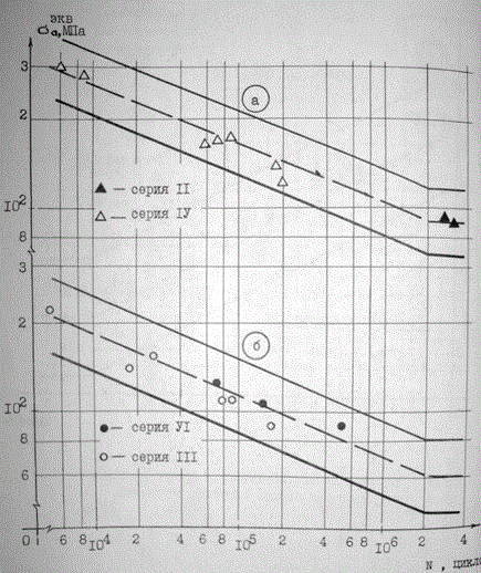
Fig. 6. Cyclic durability and fatigue curves of welded joints of flanges with the profile of prototypes of various series;
a - joints with cutting edges, b - without cutting.
In the same graph, dashed lines indicate the experimental fatigue curves, and solid lines indicate the boundaries of the tri-standard dispersion range of possible values \u200b\u200bof the durability of welded joints of the FS. The lower envelopes of the ranges are taken as the calculated fatigue curves (Fig. 7, curves 2.4). Similarly, based on experimental studies, calculated fatigue curves Nos. 1,3,5 were obtained, the mathematical expression of which has the form

Based on the research results, an engineering methodology has been developed for calculating the fatigue of FS structural elements that perceive cyclic tensile loads. The cyclic durability of the joints of the studied structural forms should be determined as the smallest of the calculated values \u200b\u200bfor the bolts and welded joints of the flanges with the profile. The calculation is recommended to be carried out according to the amplitude of the nominal stresses of the cycle using the above calculated fatigue curves and equations (1) - (7).

Fig. 7. Estimated Fatigue Curves
welded joints of flanges with a profile;
1- with cutting edges and subsequent
machining a weld;
2 - with and without cutting;
3 - the same with undercut seam;
4 - without cutting edges with a raw seam.
5 - the same with undercut seam.
Doctor of Technical Sciences V.V. Biryulyov considered the issue of designing and calculating beams with flange joints.
Mounting joints in both conventional and lightweight beams have three structural solutions: welded (without overlays and with overlays), shear-resistant (with overlays on shear-resistant high-strength bolts), flange (on high-strength bolts).
Welded joints without overlays are the least metal-intensive, but require significant labor costs of highly qualified welders. In addition, when welding joints in the cold season, additional measures are necessary to ensure the quality and reliability of the joints.
Shear-resistant joints are less time-consuming to manufacture, do not require high qualification of installers, are easier to perform at low temperatures, more reliable in operation under dynamic and cyclic loads, since they do not create stress concentrations and residual temperature stresses, like welds.
Flange connections, in turn, have several advantages over shear-resistant ones. In flanged joints, the metal consumption for a joint decreases, the number of bolts decreases by 3 ... 3.5 times (in shear-resistant joints, the bolts are placed on both sides and loaded equally in compressed and stretched zones, the bearing capacity for shear is less than the tensile bearing capacity. Number of bolts in the compressed area in the flange joints can be reduced, since they do not transmit normal forces, but only provide the transmission of transverse forces due to friction of the flange surfaces. an unstretched belt, and the bolts work more efficiently than during shear, which implies that the laboriousness of mounting flange joints is reduced by 3.5 ... 4 times .In addition, the laboriousness of manufacturing beams is reduced, mainly due to a sharp reduction in the number of holes in the wall and belts.
Bolts in flange joints are installed at the same distance or are concentrated in the stretched zone near the belt. The thickness and width of the flange in this place sometimes increase, and part of the flange in the stretched zone is made of more durable steel, and in the compressed low-loaded stretched zone is made of mild steel. With powerful belts, the number of bolts on each side of the wall in a row is brought to 3 ... 4 pieces.
When calculating a flange connection, strength should be checked in four zones - in high-strength bolts, in flanges, in welds that attach flanges, in the main section of beams at welds. The flanges are checked for strength during bending, as well as with a possible surface separation in the heat-affected zone.
A very approximate calculation of the flange connection in the beams is carried out on the assumption that the forces in the bolts are distributed in proportion to the distance from the point of application of the resultant force in the compressed zone, for example, from the center of the compressed belt to the bolt. Then the force in the most stressed extreme bolt will be

where is the distance to the i-ro row and to the extreme row of bolts; - the number of bolts in the i-th and extreme row; m - the number of rows.
Such a distribution of forces can only be with very thick flanges.
The actual operation of the flanges is complex. If a strip is cut out in the flange, then it can be represented as a kind of beam under the action of the system of forces Pf, Nb, V. The force Pf is transferred from the beam (wall or belt) to the flange, Nb is the force that occurs in the bolt after external load. Force V is usually called lever. This is the resultant resulting from the joint pressing of two flanges to each other; the position of the resultant depends on a number of factors, primarily on the thickness of the flanges.
If we imagine that the flange does not deform, then under load a bending moment arises (at the wall or shelf) equal to Nbc. The presence of leverage reduces the value of this moment, therefore, the required thickness of the flange. The influence of leverage is taken into account when calculating flange joints.
There is a proposal to use the reserves of the bearing capacity of the flange connection if we allow the development of plastic deformations in the beam section and in the flanges and apply the method of ultimate equilibrium for their assessment.
The determined flange thickness in this case will be minimal. In addition, the development of plastic deformations in the flanges will cause an increase in the deflection of the beam, as the experiments show, by 5 ... 15%. Therefore, before the accumulation of additional experimental data, such a method can be used to calculate flange connections only in low-responsible structures.
It is assumed that from the deformable surface of the flange to the cross section of the beam adjacent to it, reactive forces are transmitted, limited in the compressed zone by the resistance of the metal of the beam Ru, and in the extended zone the ultimate force necessary for the formation of a plastic mechanism in the design strip of the flange. It is accepted that the strip is rigidly pinched along the line of placement of the bolts and that these strips at the wall and shelf of the beam work independently.
Prior to the calculation, the following are established: the dimensions of the flanges, taking into account the dimensions of the beams, the diameter of high-strength bolts, the minimum number of bolts necessary to absorb the tensile force of the I-belt. Bolts are placed at the minimum possible distance from shelves and walls.
The calculation algorithm is presented in Fig. 8. In addition to the notation in Fig. 8: - load factor of an I-beam by a bending moment;
Literature
- Recommendations for the calculation, design, manufacture and installation of flange joints of steel building structures. M., TsBNTI Minmontazhspetsstroy USSR, 1989, p. 53.
- Grudev I.D. Strength of flange joints of open profile elements. Bolted and special mounting connections in steel building structures. International colloquium. - 1989. - Transactions. T.2 - S. 7-13.
- Flange connections. Calculation and design. Bugov A.U. - L. Mechanical Engineering, 1975. - p. 191.
- Soskin A. G. Features of behavior and calculation of bolts of flange connections. Bolted and special mounting joints in steel building structures. International colloquium. - 1989. - Transactions. T.2 - S. 24-31.
- Kalenov V.V., Soskin A.G., Evdokimov V.V. Research and calculation of fatigue strength of flange joints of tensile structural elements. Bolted and special mounting joints in steel building structures. International colloquium. - 1989. - Transactions. T.2 - S. 41-17.
- Design of metal structures: Special course. Textbook for high schools / V.V. Biryulev, I.I. Koshin, I.I. Krylov, A.V. Silvestrov. - L .: Stroyizdat, 1990 - 432 p.
Wish us success - click on Google+!


