Form of tightening bolt connections. Mounting connections with high strength bolts
font size
BEARING AND ENCLOSING CONSTRUCTIONS- CONSTRUCTION NORMS AND RULES- SNiP 3-03-01-87 (approved by the Decree of the USSR Gosstroy from 04-12-87 ... Actually in 2017
Mounting connections on high strength bolts controlled tension<*>
4.20. Workers who have undergone special training, confirmed by an appropriate certificate, may be allowed to make connections on bolts with controlled tension.
4.21. In shear-resistant joints, the contacting surfaces of the parts should be processed in the manner prescribed in the design.
From surfaces subject to and not to be treated steel brushes, it is necessary to remove oil contamination first.
The condition of the surfaces after processing and before assembly should be monitored and recorded in a journal (see mandatory annex 5).
Prior to assembling joints, treated surfaces must be protected from dirt, oil, paint and ice formation. If this requirement is not met or the assembly of the joint begins after more than 3 days after preparation of the surfaces, their treatment should be repeated.
4.22. The difference in surfaces (deplanation) of the joined parts above 0.5 and up to 3 mm should be eliminated by machining by forming a smooth bevel with a slope of no steeper than 1:10.
If the difference is more than 3 mm, it is necessary to install gaskets of the required thickness, processed in the same way as the connection parts. The use of gaskets is subject to agreement with the organization - the project developer.
4.23. The holes in the parts during assembly must be aligned and secured against movement by plugs. The number of plugs is determined by the effect of mounting loads, but they must be at least 10% with the number of holes 20 or more and at least two with a smaller number of holes.
In the assembled package, fixed by corks, blackness (mismatch of holes) is allowed, which does not interfere with the setting of bolts that is free without distortion. A gauge with a diameter of 0.5 mm larger than the nominal diameter of the bolt should go through 100% of the holes of each connection.
It is allowed to clean the holes of tightly tightened packages with a drill whose diameter is equal to the nominal diameter of the hole, provided that the blackness does not exceed the difference in the nominal diameters of the hole and bolt.
The use of water, emulsions and oil when cleaning holes is prohibited.
4.24. It is forbidden to use bolts that do not have temporary resistance on the head of the factory marking, the brand of the manufacturer, symbol melting numbers, and on bolts of climatic modification ХЛ (according to GOST 15150-69) -also the letters "ХЛ".
4.25. Before installation, bolts, nuts and washers must be prepared.
4.26. The bolt tension specified by the project should be ensured by tightening the nut or by rotating the bolt head to the estimated torque, or by turning the nut through a certain angle, or in any other way, guaranteeing the achievement of the specified tension force.
The order of tension should exclude the formation of leaks in tightened bags.
4.27. Torque wrenches for tensioning and tension control of high-strength bolts must be calibrated at least once per shift in the absence of mechanical damage, and also after each replacement of the control device or repair of the key.
4.28. The estimated torque M, necessary for tensioning the bolt, should be determined by the formula
where K is the average value of the coefficient of twisting, established for each batch of bolts in the certificate of the manufacturer or determined at the installation site using control devices;
P is the calculated bolt tension specified in the working drawings, N (kgf);
d is the nominal diameter of the bolt, m
4.29. Bolt tension in the angle of rotation of the nut should be made in the following order:
tighten all bolts in the connection by hand with a mounting wrench to a handle length of 0.3 m;
rotate the bolt nuts 180 ° ± 30 °.
This method is applicable for bolts with a diameter of 24 mm with a bag thickness of up to 140 mm and the number of parts in the bag up to 7.
4.30. Under the head of the high-strength bolt and high-strength nut, one washer must be installed in accordance with GOST 22355-77. It is allowed, if the hole and bolt diameters are not more than 4 mm, the installation of one washer only under the element (nut or bolt head), the rotation of which ensures the tension of the bolt.
4.31. Nuts that are tightened to rated torque or by turning a certain angle should not be fastened further.
4.32. After tightening all the bolts in the joint, the senior worker-assembler (foreman) is obliged to put the mark (assigned number or sign) in the place provided.
4.33. Bolt tension should be controlled:
with the number of bolts in the connection up to 4 - all bolts, from 5 to 9 - at least three bolts, 10 or more -10% of the bolts, but at least three in each connection.
The actual torque should be no less than the calculated one, determined by the formula (1), and not exceed it by more than 20%. Deviation of the angle of rotation of the nut is allowed within ± 30 °.
If at least one bolt is found that does not meet these requirements, double the number of bolts is subject to inspection. If one bolt with a lower torque value or with a smaller angle of rotation of the nut is detected during repeated testing, all bolts must be checked to bring the torque or angle of rotation of each nut to the required value.
The 0.3 mm thick probe should not enter the gaps between the connection parts.
4.34. After controlling the tension and accepting the joint, all the outer surfaces of the joints, including the bolt heads, nuts and the parts of the bolt threads protruding from them, must be cleaned, primed, painted, and cracks in the places of thickness differences and gaps in the joints are putty.
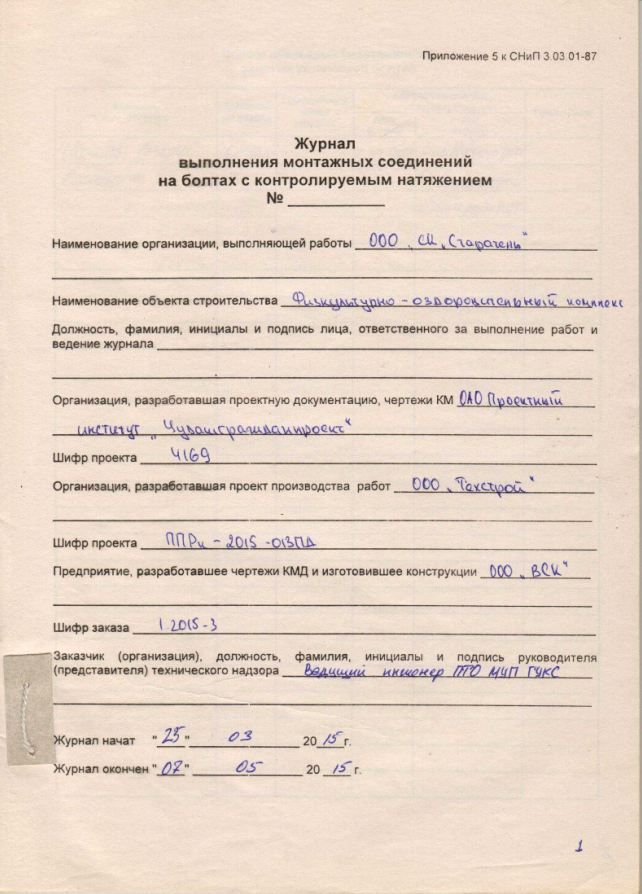
4.35. All work on tensioning and tension control should be recorded in the connection log for bolts with controlled tension.
4.36. Bolts in flange connections must be stretched to the forces indicated in the working drawings by turning the nut to the calculated torque. Tension control is subject to 100% bolts.
The actual torque should be no less than the calculated one, determined by the formula (1), and not exceed it by more than 10%.
Clearance between the contacting planes of the flanges at the locations of the bolts is not allowed. The probe with a thickness of 0.1 mm should not penetrate into a zone with a radius of 40 mm from the axis of the bolt.
I affirm
Director ___________________
___________ .___________________
1. GENERAL PROVISIONS
1.1. High-strength bolts, nuts and washers should be used in accordance with the instructions of the workers (KM) or detailing (KMD) drawings of steel structures of the mounted object.
1.2. Projects of works (PPR) should contain schemes of work or technological mapsproviding for the implementation of connections on high-strength bolts in the specific conditions of the mounted object.
1.3. The preparation, assembly and acceptance of connections on high-strength bolts should be carried out under the direction of a person (foreman, foreman), appointed by the order for the installation organization responsible for making this type of connection at the facility.
1.4. To make connections on high-strength bolts, fitters who are at least 18 years old and have passed special theoretical and practical training, confirmed by a personal certificate for the right to perform these works, issued by the installation organization, are allowed.
2. TECHNICAL REQUIREMENTS
2.1. Material Requirements
2.1.1. High-strength bolts, nuts, washers must be delivered to the mounted object in batches equipped with certificates in accordance with the requirements of GOST 22353-77, GOST 22354-77, GOST 22355-77, GOST 22356-77.
2.1.2. For sandblasting (bead-blasting) processing contact surfaces connected structural elements, quartz sand according to GOST 8736-77 or shot from cast iron or steel according to GOST 11964-81 E.
2.1.3. For the formation of a stick coating on the contact surfaces of the linings, glue based on epoxy-diane resin ED-20 according to GOST 10587-76 and carborundum powder grades KZ and KCH, fractions No. 8, 10, 12 according to GOST 3647-80 should be used.
2.1.4. Acetylene according to GOST 5457-75 and oxygen according to GOST 6331-78 should be used for flame treatment of surfaces. Acetylene and oxygen must be supplied to the place of work in steel cylinders according to GOST 15860-70.
2.2. Requirements for connectable structural members and tool
2.2.1. The possibility of free supply of high-strength bolts and tightening nuts with the use of wrenches and torque wrenches should be provided by a constructive solution to the joints.
2.2.2. Installation of joints is not allowed if there are burrs on structural elements around and inside the holes, as well as along the edges of the elements.
The contact surfaces of the elements are not primed and painted. The distance between the axis of the bolts of the last row and the primed surface must not be less than 70 mm.
2.2.3. It is not allowed to use elements with dimensional deviations in the joints that do not meet the requirements of SNiP III-18-75 “Rules for the production and acceptance of work. Metal constructions". The difference in the planes of the elements connected by the plates should not exceed 0.5 mm inclusive.
2.2.4. In joints from rolling profiles with non-parallel surfaces of the shelves, leveling gaskets should be used.
2.2.5. The nominal diameters and blackness of the holes (mismatch of the holes in the individual parts of the assembled package) should not exceed the requirements specified in chapter SNiP III-18-75 “Rules for the production and acceptance of work. Metal constructions".
2.2.6. The control and calibration torque wrenches should be numbered, calibrated and provided with calibration schedules or tables. Pneumatic and electric wrenches must meet the passport requirements.
3.1. Preparatory operations
3.1.1. Preparatory operations include: re-preservation and cleaning of high-strength bolts; preparation of structural elements; control and calibration check of the tool.
3.1.2. High-strength bolts, nuts, washers must be cleaned from factory preservation, dirt, rust and covered with a thin layer of grease. Deconservation and cleaning are carried out according to the following technology.
3.1.3. Place high-strength bolts, nuts and washers with a weight of not more than 30 kg in a lattice container.
3.1.4. Immerse the lattice containers filled with hardware in a tank with boiling water for 8 - 10 minutes (see drawing).
3.1.5. After boiling, wash the hot metalware in a mixture consisting of 85% unleaded gasoline according to GOST 2084-77 and 15% engine oil (type autol) according to GOST 20799-75 by 2 to 3 times immersion followed by drying.
3.1.6. Place the treated bolts, nuts and washers separately in closed boxes with handles with a capacity of not more than 20 kg to transfer them to the workplace.
3.1.7. On portable containers indicate the sizes, the number of bolts, nuts and washers, the processing date, certificate numbers and lots.
3.1.8. The cleaned bolts, nuts and washers should be stored in closed boxes for no more than 10 days, after which it is necessary to re-process in accordance with paragraphs. 3.1.4 and 3.1.5.
3.1.9. Burrs found around and inside the holes, as well as around the edges of the elements, must be removed completely. Deburring around the holes and at the edges of the elements should be done with pneumatic or electric cleaning machines without forming a recess that disrupts the contact of the contacting surfaces, and in the case of burrs inside the hole, with a drill whose diameter is equal to the diameter of the bolt.
3.1.10. When the difference in the planes of the connected elements is more than 0.5 to 3.0 mm, inclusive, on the protruding element, it is necessary to make the bevel a cleaning pneumatic or electric machine at a distance of 30.0 mm from the edge of the element. If the plane difference is more than 3.0 mm, leveling pads should be used.
3.1.11. Calibration (verification of calibration) of control and calibration torque wrenches should be performed once per shift before starting work on special stands or fixtures in accordance with the recommended Appendix 1. Calibration of wrenches is performed in accordance with the recommended Appendix 2.
Device for boiling high-strength bolts, nuts and washers
1 - heating element; 2 - trellised container for bolts; 3 - a tank for water;
4 - drain plug
3.2. Basic technological operations
3.2.1. The main technological operations include:
- processing of contact surfaces;
- assembly of connections;
- installation of high strength bolts;
- tension and control of tension of bolts.
3.2.2. The method of processing contact surfaces is selected in accordance with the coefficient of friction specified in the drawings KM or KMD, and chapter SNiP II-23-81 " Steel structures. Design Standards. "
The following contact surface treatment methods have been established that are performed at the installation site: sandblasting (shot blasting); gas flame; metal brushes; kleefrictionny.
3.2.3. Sandblasting (bead-blasting) processing of the contact surfaces of the elements to be connected should be carried out by sandblasting or bead-blasting machines in accordance with GOST 11046-69 (ST SEV 3110-81).
When sandblasting (shot-blasting) contact surfaces, mill scale and rust must be completely removed until a homogeneous surface is light gray in color.
3.2.4. Gas-flame treatment of contact surfaces must be carried out using wide-range gas-flame burners GAO-60 or GAO-2-72 in accordance with GOST 17357-71.
Gas-flame treatment is allowed with a metal thickness of at least 5.0 mm.
The burner travel speed of 1 m / min with a metal thickness of more than 10 mm and 1.5-2 m / min - with a metal thickness of up to 10 mm inclusive.
Combustion products and scale should be swept away with soft wire and then hair brushes.
The surface after flame treatment must be free from dirt, paint, oil stains and easily exfoliated scale. Complete removal of mill scale is optional.
Gas flame processing equipment and brief technical specifications equipment are given in recommended appendix 3.
3.2.5. Processing of contact surfaces with metal brushes should be carried out using pneumatic or electric cleaning machines, the brands of which are indicated in the recommended Appendix 4.
It is not allowed to bring the cleaned contact surfaces to a metallic luster.
3.2.6. The adhesive coating on the contact surfaces of the pads, as a rule, is applied at manufacturing plants of metal structures.
The technological process for the production of adhesive coating provides for:
- processing of contact surfaces of linings in sandblasting (shot-blasting) devices according to GOST 11046-69 (ST SEV 3110-81);
- applying epoxy-polyamide glue to the treated contact surfaces;
- application of uncured glue carborundum powder.
The safety of the adhesive coating should be ensured by the packing of the linings for the entire period of their loading, transportation, unloading and storage at the construction site.
The shelf life of glued friction linings is unlimited.
The composition of the adhesive coating is given in recommended Appendix 5.
The contact surfaces of the main elements to be connected must be brushed with metal in accordance with clause 3.2.5 before assembly.
3.2.7. Metallization processing of the contact surfaces of the connected structural elements (galvanizing, aluminizing), as a rule, is carried out at manufacturing plants of metal structures.
3.2.8. Treated surfaces must be protected from dirt, oil, and ice formation. The shelf life of structures treated with sandblasting (shot-blasting), flame methods or metal brushes, before assembly should not exceed three days, after which it is necessary to re-treat the surfaces in accordance with paragraphs. 3.2.3 - 3.2.5.
Surfaces treated by sandblasting (bead-blasting) during repeated processing may be cleaned with a gas-flame method.
3.2.9. Contact surfaces without treatment should be cleaned of dirt and peelable scale with metal brushes; from oil - unleaded gasoline, from ice - by chipping.
3.2.10. Assembling joints on high-strength bolts includes the following operations:
- combination of holes and fixing in the design position of the connection elements using assembly plugs, the number of which should be 10% of the number of holes, but not less than 2 pcs .;
- installation of high-strength bolts in openings free from assembly plugs;
- tight screed package;
- the tension of the installed high-strength bolts for the force specified in the drawings of KM and KMD;
- removing assembly plugs, setting high-strength bolts into the vacated holes and tensioning them to the design effort;
- primer compound.
3.2.11. Under the heads and nuts of high-strength bolts, it is necessary to put only one heat-treated washer according to GOST 22355-77.
The protruding end of the bolt must have at least one thread of thread over the nut.
3.2.12. If the holes do not coincide, their reaming in the elements with machined surfaces should be carried out without using coolants.
3.2.13. Preliminary and final tensioning of high-strength bolts must be carried out from the middle of the joint to the edges or from the most rigid part of the joint towards its free edges.
3.2.14. The method of tensioning high-strength bolts should be indicated in the drawings of KM or KMD.
3.2.15. If there are no instructions, the tensioning method is chosen by the installation company according to the recommended Appendix 2.
4. RULES OF ACCEPTANCE AND METHODS OF CONTROL
4.1. After making the installation connection on high-strength bolts, the team leader must stamp the connection with a personal stamp (a set of numbers) and present the finished connection to the person in charge.
4.2. The responsible person (foreman, foreman) after inspection and verification must present the finished connection to the customer’s representative. If the customer does not have comments, the connection should be considered accepted and the responsible person will enter all necessary information about him into the execution log mounting connections on high-strength bolts (see mandatory annex 6).
4.3. After acceptance, the finished compound should be primed and painted. Grades of soil and paints and varnishes are accepted according to the "List of polymeric materials and products approved for use in construction", approved by the USSR Ministry of Health, the same as for priming and painting of metal structures. Grades of soil and paint should be indicated in the drawings of KM and KMD.
4.4. The responsible person checks the quality of the connections on high-strength bolts by means of operational control. The following shall be subject to control:
- the quality of processing of contact surfaces;
- compliance of the installed bolts, nuts and washers with the requirements of GOST 22353-77, GOST 22354-77, GOST 22355-77, GOST 22356-77, as well as other requirements specified in the drawings KM and KMD;
- the presence of washers under the heads of bolts and nuts;
- the presence on the heads of the bolts of the brand of the manufacturer;
- the length of the protruding part of the thread of the bolt above the nut;
- the presence of the stigma of the foreman leading the assembly of the compound.
4.5. The processing quality of contact surfaces is checked by visual inspection immediately before assembling the joints. The results of the control must be recorded in the journal (see mandatory appendix 6).
4.6. The compliance of the bolt tension with the design is checked depending on the tension method. The deviation of the actual twisting moment from the moment indicated in the KM and KMD drawings should not exceed 20%.
The angle of rotation of the nut is determined by the position of the marks on the protruding end of the bolt and nut. With a two-stage bolt tension, the deviation of the angle of rotation should be within ± 15 °, with a single-stage - ± 30 °.
Bolts in which the position of the marks is outside the specified limits must be loosened and tightened again.
4.7. The tension of the high-strength bolts is checked with a calibrated torque wrench or a calibrated control wrench.
Bolt tension should be controlled by a random check: with the number of bolts in the joint up to 5 inclusive, 100% of the bolts are controlled, with the number of bolts from 6 to 20 - at least 5, with a larger number - at least 25% of the bolts in the joint.
4.8. If during inspection at least one bolt is found, the tension of which does not meet the requirements of clause 4.6 of this standard, then 100% of the bolts in the connection are subject to control. In this case, the tension of the bolts should be brought to the required value.
4.9. The density of the contractible bag is controlled with 0.3 mm probes. The probe should not pass between the planes along the contour of the connected elements.
4.10. The documentation presented upon acceptance of the finished object, except for the documentation provided for by chapter SNiP III-18-75 “Rules for the production and acceptance of work. Metal structures ”, must contain:
- a log of mounting connections on high-strength bolts;
- certificates for bolts, nuts and washers;
- certificates for materials for the formation of adhesive coatings.
5. SAFETY REQUIREMENTS
5.1. The organization of the site of the enlarged assembly of structures with mounting joints on high-strength bolts should ensure the safety of workers at all stages of the work.
The installation of structures on high-strength bolts must be carried out in accordance with the PPR containing the following safety decisions:
- organization of jobs and walkways;
- sequence of technological operations;
- methods and devices for the safe work of installers;
- location and coverage of mounting mechanisms;
- methods of storage of building materials and structural elements.
5.2. The placement of working equipment and the organization of workplaces should ensure the safety of the evacuation of workers in emergency situations, taking into account existing building codes.
5.3. All work at height on the implementation of mounting connections on high-strength bolts should be done from the scaffolding, providing free access to the connection with the tool.
Means of conditioning and other devices that ensure the safety of work must comply with the requirements of Chapter SNiP III-4-80 “Rules for the production and acceptance of work. Safety measures in construction ”, GOST 12.2.012-75, GOST 24259-80 and GOST 24258-80.
5.4. Electrical safety at the installation site should be provided in accordance with the requirements of GOST 12.1.013-78.
5.5. When treating contact surfaces with sandblasting (shot-blasting) devices, the “Rules for the design and safety of the operation of pressure vessels” approved by the USSR State Technical Supervision Service should be followed.
5.6. The place of sandblasting (shot-blasting) should be fenced and appropriate warning signs and inscriptions should be hung near it.
5.7. Materials for sandblasting (shot-blasting) surface treatment (sand, shot, metal sand) should be stored in containers with a tightly closed lid.
5.8. The operator of the sand-blasting (shot-blasting) apparatus and the auxiliary worker are supplied with spacesuits or helmets with forced supply of clean air.
5.9. Air supplied to the spacesuit must first be passed through a filter to remove dust, water and oil.
5.10. Between the operator’s and auxiliary worker’s workstations located near the sandblasting machine (bead-blasting), sound or light alarm should be provided.
5.11. When treating contact surfaces with metal brushes (manual and mechanical), workers must be equipped with goggles according to GOST 12.4.003-80 or masks, mittens and respirators.
5.12. When treating contact surfaces in a gas-flame manner, it is necessary to comply with the requirements of Chapter SNiP III-4-80 “Rules for the production and acceptance of work. Safety in construction ”, as well as sanitary rules for welding and cutting of metals, approved by the USSR Ministry of Health.
5.13. Places for the production of gas-flame operations must be exempted from combustible materials in a radius of at least 5 m, and from explosive materials and installations (including gas cylinders and gas generators) within a radius of 10 m.
5.14. It is not allowed to carry out work on gas-flame treatment of surfaces of structural elements in rainy weather outdoors without a canopy.
5.15. When performing flame treatment of contact surfaces, workers must be provided with goggles of a closed type with glass-filters of the grades G-1 or G-2.
Auxiliary workers must be provided with goggles with glasses-filters of grades B-1 or B-2.
5.16. The application of the adhesive layer on the surface of the linings, as a rule, should be performed at the manufacturing plants. In this case, the safety requirements in accordance with GOST 12.3.008-75, GOST 12.3.016-79 and GOST 10587-76, as well as safety rules when working with synthetic adhesives, must be observed.
5.17. The preparation of glue and the application of adhesive coatings should be carried out in a separate room equipped with exchange and local ventilation.
5.18. Persons working with epoxy-diane resins should be provided with protective clothing and gloves.
To protect the skin from the effects of epoxy-diane resins, protective pastes and ointments based on lanolin, petroleum jelly or castor oil should be used.
5.19. The room for applying adhesive coatings should be provided with fire extinguishing means - carbon dioxide and foam extinguishers.
5.20. Depreservation of bolts, nuts and washers should be carried out in an open area with a canopy.
5.21. When boiling hardware in water, the bath must be grounded. Workers who re-preserve hardware should not have direct contact with boiling and lubrication baths. The loading process should be mechanized.
5.22. During assembly operations, the alignment of the holes and verification of their coincidence in the mounted structural elements must be carried out using a special tool - cone mandrels, assembly plugs, etc. Checking the coincidence of the holes with your fingers is not allowed.
5.23. The operation of mechanisms, means of small-scale mechanization, including maintenance, should be carried out in accordance with the requirements of Chapter SNiP III-4-80 “Rules for the production and acceptance of work. Safety in construction ”and manufacturers' instructions.
5.24. When using hand-held machines, the safety rules stipulated by GOST 12.1.012-79 (ST SEV 1932-79, ST SEV 2602-80) and GOST 12.2.010-75, as well as the instructions of manufacturers, must be observed.
5.25. The working regime for working with manual electric and pneumatic machines and wrenches should be established in accordance with the "Recommendations for the development of the Regulation on the working regime of workers in vibro-hazardous professions", approved in December 1971 by the All-Union Central Council of Trade Unions, the Ministry of Health of the USSR, and the State Committee of the Council of Ministers of the USSR for Labor and wages, as well as instructions from manufacturers to perform work with specific types of machines.
5.26. The priming and painting of finished joints on high-strength bolts should be done at the site of assembly of metal structures.
5.27. Only workers who know the rules for safe handling of the equipment and materials used and are familiar with the fire safety rules are allowed to work on priming the joints.
5.28. Workers involved in the sizing and painting of compounds must undergo a medical examination in accordance with the requirements of Order No. 400 of the USSR Ministry of Health dated 05/30/1969 "On preliminary screening and periodic medical examinations of workers."
5.29. Temporary production and auxiliary rooms must be equipped with ventilation and lighting, as well as fire extinguishing equipment in accordance with the requirements of GOST 12.4.009-75.
Calibration Example torque wrench type KTR-3 1
_________________
1 KTR-3 keys are manufactured by installation organizations according to the drawings of the Central Research Institute of Steel Construction.
Torque wrenches are calibrated at special calibration stands or by hanging a load of a given value to its handle. A torque wrench is hung on a hexagonal mandrel or a tightened high-strength bolt so that its handle occupies a horizontal position (see drawing).
At a fixed point on the end of the key, a load of mass
where M s - estimated torque;
D M s - the moment equal to the product of the mass of the key by the distance from its center of gravity to the axis of the mandrel or bolt;
l - the distance from the center of gravity of the load to the axis of the mandrel or bolt.
When the load is suspended, the countdown is carried out by a recording device, for example, an indicator of the clock type IC 10 mm according to GOST 577-68. The measurement is carried out 2-3 times until a stable result is obtained. Calibration results are entered in the key calibration calibration log (see mandatory appendix 7).
Torque wrench calibration scheme

1 - a welded hexagon or a tightened high-strength bolt;
2 - rigid support; 3 - indicator; 4 - calibrated key; 5 - calibrated cargo
High tension bolt tensioning methods
1. Tension of high-strength bolts at the moment of tightening
1.1. The tension of high-strength bolts for the design effort should be made by tightening the nuts with a torque wrench to the estimated value of the torque. The value of the torque M srequired for tensioning high-strength bolts is determined by the formula:
M s = kPd,
k - the average value of the twisting coefficient for each batch of bolts according to the certificate or set with the help of control devices at the installation site;
R - the tension force of the bolt specified in the drawings KM and KMD;
d - nominal diameter of the bolt.
1.2. To pre-tighten the nuts, use pneumatic or electric wrenches specified in recommended Appendix 4 and torque wrenches.
1.3. When tightening the bolt, keep the head or nut from turning with a mounting wrench. If the rotation does not stop as the bolt is pulled, then the bolt and nut must be replaced.
1.4. The tightening torque should be recorded during the movement of the key in the direction that increases the tension.
Tighten smoothly without jerking.
1.5. Torque wrenches must be numbered and calibrated. They should be calibrated at the start of the shift.
2. Tension of high-strength bolts along the angle of rotation of the nut
2.1. High-strength bolts must be installed in openings free of assembly plugs and tightened with a wrench, adjusted at the time of tightening 800 N × m. Tightening of each bolt must be done before stopping the rotation of the nut. After removing the assembly plugs and replacing them with bolts, the latter should be tightened at the time of tightening 800 N × m.
2.2. To control the angle of rotation of the nuts, it is necessary to mark the protruding ends of the bolts with a combined center punch (see diagram) or paint.
Combined punch
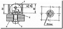
1 - punch; 2 - a nut; 3 - high strength bolt; 4 - package
2.3. The final tightening is carried out with a wrench adjusted at the moment of tightening 1600 N × m, while the nut should rotate by the angle indicated in the table.
3. Calibration of wrenches by the angle of rotation of the nut
3.1. Calibration of wrenches should be performed on a special calibration package consisting of three bodies with a number of holes of at least 20.
High-strength bolts are inserted into the holes of the calibration package and tightened with a wrench until the nut stops turning. A group of bolts (calibration bolts) in an amount of at least 5 pcs. don't drag out.
The calibration bolts must be tightened manually with a mounting key with a handle length of 0.3 m to failure (initial position).
3.2. On the prepared calibration bolts, a wrench is calibrated.
3.3. The compressed air pressure is set so that when the nut is rotated through an angle of 180 ± 30 ° from the initial position, the wrench will fail.
Air pressure must be checked periodically.
Air pressure control should be carried out according to the GOST 2405-72 pressure gauge installed in the place where the wrench hose is connected to the line.
3.4. When calibrating the wrench (to monitor the angle of rotation of the nut), risks must be applied to its interchangeable head.
3.5. A wrench is considered calibrated if the angle of rotation of the nut during the tension of all bolts at the time of failure of the wrench is 180 ± 30 °.
3.6. The results of the wrench calibration must be entered in the wrench calibration log (see mandatory appendix 8).
3.7. In the event of a change in the compressed air pressure after eliminating the malfunction in the wrench, it is necessary to carry out a check calibration.
APPENDIX 3
Fire Post Equipment
|
Name of equipment |
Brief technical specification |
|
Burner GAO-60, GAO-2-72 GOST 17357-71 (1 pc.) |
Wide, multi-flame, working width 100 mm. |
|
Oxygen cylinders (3 pcs.) |
|
|
Acetylene cylinders (2 pcs.) |
|
|
Reducer balloon oxygen DKD15-65 or RKD-15-81 |
Maximum inlet overpressure - 1962 × 10 4 Pa; working overpressure - 78.48 × 10 4 Pa; throughput at maximum pressure - 23 m 3 / h |
|
Reducer balloon acetylene RD-2AM, DAP-1-65 |
Maximum inlet overpressure - 245.25 × 10 4 Pa; working overpressure - from 0.981 × 10 4 Pa \u200b\u200bto 14.715 × 10 4 Pa; throughput - 5 m 3 / h |
|
Rubber-fabric sleeves for oxygen supply (GOST 9356-75) with an inner diameter of 9.0 and an outer diameter of 18 mm |
Operating overpressure 147.15 × 10 4 Pa |
APPENDIX 4
Equipment, mechanisms and tools used for processing contact surfaces, connected elements and tensioning high-strength bolts
The vibration levels of electric and pneumatic grinding hand machines and wrenches (Table 1) do not exceed those established in GOST 16519-79 (ST SEV 716-77) and GOST 12.1.012-78.
Table 1
|
Name |
Brand Standard |
Appointment |
|
Electric Impact Wrenches |
For tightening high-strength bolts during installation and assembly work |
|
|
Pneumatic Impact Wrenches |
GOST 15150-69 GOST 10210-74 |
|
|
Spanners |
To preassemble connections |
|
|
Electric Grinding Hand Machines |
For stripping work |
|
|
Electric angle grinder hand machines |
||
|
Pneumatic Stripping Hand Machines |
For cleaning metal surfaces from rust and scale |
|
|
Gas burners |
GOST 17357-71 |
For contact surfaces |
Noise levels of electric and pneumatic grinding manual machines and wrenches do not exceed those established in GOST 12.1.003-76. Vibration parameters and noise characteristics of electric and pneumatic manual machines used in the processing of contact surfaces of connected elements and for tensioning high-strength bolts are given in table. 2 and 3.
table 2
Vibration parameters
|
Logarithmic levels of vibration velocity, dB |
||||||||
Table 3
Noise characteristics
|
Geometrical mean frequencies of octane bands, Hz |
||||||||
|
Sound power level, dB |
||||||||
The composition of the adhesive coating
|
Name |
Cooking method |
|
|
Epoxy polyamide adhesive |
ED-20 epoxy according to GOST 10587-76 (100 wt.h) |
A hardener and an accelerator are introduced into the epoxy resin; the resulting mixture is thoroughly mixed |
|
Hardener I-5M (I-6M) according to VTU OP-2382-65-60 (50 wt. H) Accelerator UP-606-2 according to MRTU 6-09-6101-69 (2 - 3 wt.) |
||
|
Abrasive material |
Carborundum powder of the KZ or KCh brand |
|
|
Solvent |
Acetone according to GOST 2768-79 |
Greetings friends. For a long time I did not write about special construction magazines, but you really like such topics. Here, for example, this article "", the most popular on my blog and has already collected more than 80 comments. Well, today I will share with you an article about the journal of the installation of bolted joints with controlled tension.
Why it should be filled
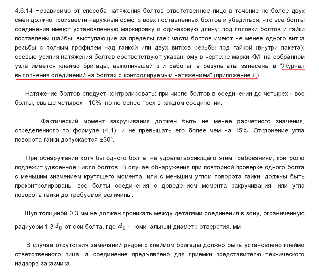
This type of connection refers to highly critical nodes where significant tensile forces arise. That is why the connection on high-strength bolts are subject to special control. In articles, I constantly refer to the set of rules "Bearing and enclosing structures" and this time will not be an exception. Section 4.6.13 of the specified set of rules says the following:
And in paragraph 4.6.14 it is also written about this journal:
And finally, p. 4.6.16:
Example of a decorated magazine
Below I have presented to you a formalized version (sample) of this magazine. In the above example, the old version is presented, the form of which was indicated in the old SNiP 3.03.01-87. But the new form has not changed much, so do not pay attention to it. He presented the magazine which he could find.
The first page is the title page
The second sheet is a list of link (installers) engaged in the installation of bolts
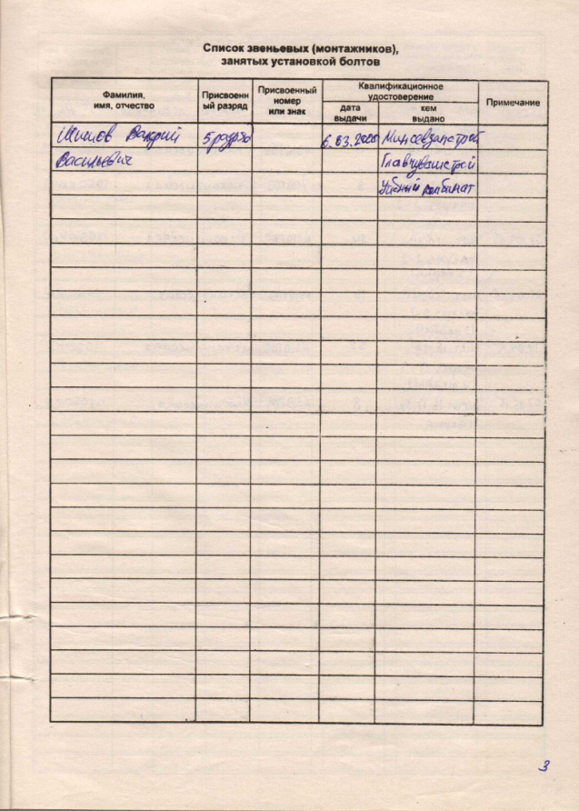
This table indicates all installers who are installing high-strength bolts. These installers must have the appropriate certificate. This is indicated in paragraph 4.6.1 of SP 70.13330.2012:
The assigned number and sign (mark), in my opinion, is taken just from the certificate. But I don’t know for sure if you correct me.
The next two sheets are basic

In paragraph 4, the certificate number for the bolts. This requirement is given in clause 4.6.5:

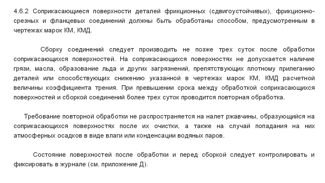
Clause 5 indicates the method of processing contact surfaces. Surface treatment is a mandatory procedure, without it, in no case can not make connections. In paragraph 4.6.2, this is very well written:
In column 6 we indicate the moment of twisting. This indicator is calculated by a certain formula. The data of the bolt (twisting coefficient and nominal diameter of the bolt) and the tension force, which is indicated in the working drawings of the KM, are taken as the basis. How to calculate the moment specified in paragraph 4.6.9:

Next page
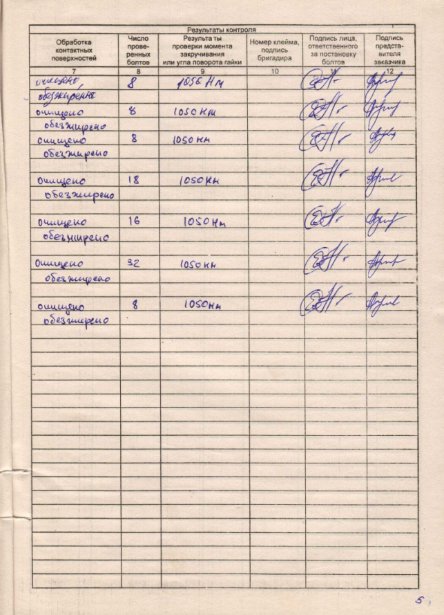
The control results are already written here. Whether surface treatment has been carried out, how many bolts have been checked, at what moment have they been tightened, etc.
And how to carry out the control and how to properly carry out the bolt tensioning work itself is described in detail in section 4.6 of SP 70.13330.2012.
Below you can download the electronic version (form) of the magazine. Use on health.
Support the blog - download the electronic version of the magazine for bolting with controlled tensioning for a nominal price!
In the payment window after successful payment click Go to the store website and the file will go to downloads.
Download for free:
P.s. Friends, I want to recommend you executive documentation program from ALTIUS SOFT Company. If you want to automate and speed up the process of maintaining executive documentation, then you can not do without this program. Thanks!
INDUSTRY STANDARD
CONSTRUCTIONS BUILDING STEEL. MOUNTING
CONNECTIONS ON HIGH STRENGTH BOLTS
Typical Process
OST 36-72-82
By order of the Ministry of Installation and Special Construction Works of the USSR of December 7, 1982, the deadline for introduction was set from July 1, 1983.
APPROVED AND INTRODUCED BY THE ORDER of the Ministry of Assembly and Special Construction Work of the USSR of December 7, 1982, No. 267
Performers: VNIPI Promstalkonstruktsiya
K.I. Lukyanov, Ph.D., A.F. Knyazhev, Ph.D., G.N. Pavlova
Co-executors: Central Research Institute Projectstalconstruction
B.G. Pavlov, Ph.D., V.V. Volkov, Ph.D., V.M. Grandmother
madi
B.M. Weinblat, Ph.D.
Introduced for the first time
This standard applies to a typical process for the implementation of shear-resistant mounting joints on high-strength bolts in building steel structures.
Standard sets technical requirements to the materials used, the connected structural elements, the tool, as well as the sequence of operations technological process, quality control, the basics of safety.
1. GENERAL PROVISIONS
1.1. High-strength bolts, nuts and washers should be used in accordance with the instructions of the workers (KM) or detailing (KMD) drawings of steel structures of the mounted object.
1.2. Projects for the production of works (PPR) should contain workflow schemes or routings providing for the implementation of connections on high-strength bolts in the specific conditions of the mounted object.
1.3. The preparation, assembly and acceptance of connections on high-strength bolts should be carried out under the direction of a person (foreman, foreman), appointed by the order for the installation organization responsible for making this type of connection at the facility.
1.4. To make connections on high-strength bolts, fitters not younger than 18 years old, who have passed special theoretical and practical training, confirmed by a personal certificate for the right to perform these works issued by the installation organization, are allowed.
2. TECHNICAL REQUIREMENTS
2.1. Material Requirements
2.1.1. High-strength bolts, nuts, washers must be delivered to the mounted object in batches equipped with certificates in accordance with the requirements of GOST 22353-77, GOST 22354-77, GOST 22355-77, GOST 22356-77.
2.1.2. For sandblasting (bead-blasting) processing of the contact surfaces of the connected structural elements, quartz sand according to GOST 8736-77 or shot from cast iron or steel according to GOST 11964-81 E should be used.
2.1.3. For the formation of a stick coating on the contact surfaces of the linings, glue based on epoxy-diane resin ED-20 according to GOST 10587-76 and carborundum powder grades KZ and KCh, fractions No. 8, 10, 12 according to GOST3647-80 should be used.
2.1.4. For flame treatment of surfaces, acetylene according to GOST 5457-75 and oxygen according to GOST6331-78 should be used. Acetylene and oxygen must be supplied to the place of work in steel cylinders according to GOST 15860-70.
2.2. Requirements for connectable structural members and tool
2.2.1. The possibility of free supply of high-strength bolts and tightening nuts with the use of wrenches and torque wrenches should be provided by a constructive solution to the joints.
2.2.2. Installation of joints is not allowed if there are burrs on structural elements around and inside the holes, as well as along the edges of the elements.
The contact surfaces of the elements are not primed and painted. The distance between the axis of the bolts of the last row and the primed surface must not be less than 70 mm.
2.2.3. It is not allowed to use elements with dimensional deviations in the joints that do not meet the requirements of SNiP III-18-75 “Rules for the production and acceptance of work. Metal structures”. The difference in the planes of the elements connected by the plates should not exceed 0.5 mm inclusive.
2.2.4. In joints from rolling profiles with non-parallel surfaces of the shelves, leveling gaskets should be used.
2.2.5. The nominal diameters and blackness of the holes (mismatch of the holes in the individual parts of the assembled package) must not exceed the requirements specified in chapter SNiP III-18-75 “Rules for the production and acceptance of work. Metal structures”.
2.2.6. The control and calibration torque wrenches must be numbered, calibrated and provided with calibration schedules or tables. Pneumatic and electric wrenches must meet the passport requirements.
3. CONTENT OF THE TECHNOLOGICAL PROCESS
3.1. Preparatory operations
3.1.1. Preparatory operations include: re-preservation and cleaning of high-strength bolts; preparation of structural elements; calibration control tool.
3.1.2. High-strength bolts, nuts, washers must be cleaned from factory preservation, dirt, rust and covered with a thin layer of grease. Preservation and cleaning are carried out according to the following technology.
3.1.3. Place high-strength bolts, nuts and washers with a weight of not more than 30 kg in a lattice container.
3.1.4. Immerse the lattice containers filled with hardware in a tank with boiling water for 8 - 10 minutes (see drawing).
3.1.5. After boiling, wash the hot hardware in a mixture consisting of 85% unleaded gasoline according to GOST 2084-77 and 15% engine oil (type autol) according to GOST 20799-75 by 2 to 3 times immersion, followed by drying.
3.1.6. Place the treated bolts, nuts and washers separately in closed boxes with handles with a capacity of not more than 20 kg to transfer them to the workplace.
3.1.7. On portable containers indicate the sizes, the number of bolts, nuts and washers, the processing date, certificate numbers and lots.
3.1.8. The cleaned bolts, nuts and washers should be stored in closed boxes for no more than 10 days, after which it is necessary to re-process in accordance with paragraphs. 3.1.4 and 3.1.5.
3.1.9. Burrs found around and inside the holes, as well as around the edges of the elements, must be removed completely. Deburring around the holes and at the edges of the elements should be done with pneumatic or electric cleaning machines without forming a recess that disrupts the contact of contacting surfaces, and in the case of burrs inside the hole, with a drill whose diameter is equal to the diameter of the bolt.
3.1.10. When the difference in the planes of the connected elements is more than 0.5 to 3.0 mm inclusive on the protruding element, it is necessary to make the bevel a stripping pneumatic or electric machine at a distance of 30.0 mm from the edge of the element. If the plane difference is more than 3.0 mm, leveling pads should be used.
3.1.11. Calibration (calibration check) of the control and calibration torque wrenches should be performed once per shift before starting work on special stands or fixtures in accordance with the recommended Appendix 1. Calibration of wrenches is performed in accordance with the recommended Appendix 2.
Device for boiling high-strength bolts, nuts and washers
1 - heating element; 2 - trellised container for bolts; 3 - a tank for water;
4 - drain plug
3.2. Basic technological operations
3.2.1. The main technological operations include:
- processing of contact surfaces;
- assembly of connections;
- installation of high strength bolts;
- tension and control of tension of bolts.
3.2.2. The method of processing contact surfaces is selected in accordance with the coefficient of friction specified in the drawings KM or KMD, and the chapter SNiP II-23-81 "Steel structures. Design Standards. "
The following methods for processing contact surfaces, performed at the installation site, were established: sandblasting (shot-blasting); gas-flame; metal brushes;
3.2.3. Sandblasting (bead-blasting) processing of the contact surfaces of the elements to be connected should be carried out by sandblasting or bead-blasting machines in accordance with GOST 11046-69 (ST SEV 3110-81).
When sandblasting (shot-blasting) contact surfaces, mill scale and rust must be completely removed until a homogeneous surface is light gray in color.
3.2.4. Gas-flame treatment of contact surfaces must be carried out by wide-angle gas-flame burners GAO-60 or GAO-2-72po GOST 17357-71.
Gas-flame treatment is allowed with a metal thickness of at least 5.0 mm.
The burner travel speed of 1 m / min with a metal thickness of more than 10 mm and 1.5-2 m / min - with a metal thickness of up to 10 mm inclusive.
Combustion products and scale should be swept away with soft wire and then hair brushes.
The surface after flame treatment must be free from dirt, paint, oil stains and easily exfoliated scale. Complete removal of mill scale is optional.
The equipment of the gas-flame processing station and a brief technical description of the equipment are given in the recommended Appendix 3.
3.2.5. Processing of contact surfaces with metal brushes should be carried out using pneumatic or electric cleaning machines, the brands of which are indicated in the recommended Appendix 4.
It is not allowed to bring the cleaned contact surfaces to a metallic luster.
3.2.6. The adhesive coating on the contact surfaces of the pads, as a rule, is applied at manufacturing plants of metal structures.
The technological process for the production of adhesive coating provides for:
- processing of contact surfaces of linings in sandblasting (shot-blasting) devices according to GOST 11046-69 (ST SEV 3110-81);
- applying epoxy-polyamide glue to the treated contact surfaces;
- application of uncured glue carborundum powder.
The safety of the adhesive coating should be ensured by the packing of the linings for the entire period of their loading, transportation, unloading and storage at the construction site.
The shelf life of glued friction linings is unlimited.
The composition of the adhesive coating is given in recommended Appendix 5.
The contact surfaces of the main connected elements before assembly must be treated with metal brushes according to clause 3.2.5.
3.2.7. Metallization processing of the contact surfaces of the connected structural elements (galvanizing, aluminizing), as a rule, is carried out at manufacturing plants of metal structures.
3.2.8. Treated surfaces must be protected from dirt, oil, and ice formation. The shelf life of structures treated with sandblasting (shot-blasting), flame methods or metal brushes, before assembly should not exceed three days, after which it is necessary to re-treat the surfaces in accordance with paragraphs. 3.2.3 -3.2.5.
Surfaces treated by sandblasting (bead-blasting) during repeated processing may be cleaned with a gas-flame method.
3.2.9. Contact surfaces without treatment should be cleaned of dirt and peelable scale with metal brushes; from oil - unleaded gasoline, from ice - chipping.
3.2.10. Assembling joints on high-strength bolts includes the following operations:
- combination of holes and fixing in the design position of the connection elements using assembly plugs, the number of which should be 10% of the number of holes, but not less than 2 pcs .;
- installation of high-strength bolts in openings free from assembly plugs;
- tight screed package;
- the tension of the installed high-strength bolts for the force specified in the drawings of KM and KMD;
- removing assembly plugs, setting high-strength bolts into the vacated holes and tensioning them to the design effort;
- primer compound.
3.2.11. Under the heads and nuts of high-strength bolts, it is necessary to put only one heat-treated washer according to GOST 22355-77.
The protruding end of the bolt must have at least one thread of thread over the nut.
3.2.12. If the holes do not coincide, their reaming in the elements with machined surfaces should be carried out without using coolants.
3.2.13. Preliminary and final tensioning of high-strength bolts must be carried out from the middle of the joint to the edges or from the most rigid part of the joint towards its free edges.
3.2.14. The method of tensioning high-strength bolts should be indicated in the drawings of KM or KMD.
3.2.15. If there are no instructions, the tensioning method is chosen by the installation company according to the recommended Appendix 2.
4. RULES OF ACCEPTANCE AND METHODS OF CONTROL
4.1. After making the installation connection on high-strength bolts, the team leader must stamp the connection with a personal stamp (a set of numbers) and present the finished connection to the person in charge.
4.2. The responsible person (foreman, foreman) after inspection and verification must present the finished connection to the customer’s representative. In the absence of comments from the customer, the connection should be considered accepted and the person responsible will enter all the necessary information about it in the log of the installation connections for high-strength bolts (see mandatory appendix 6).
4.3. After acceptance, the finished compound should be primed and painted. Soil and paint grades are accepted according to the "List of polymeric materials and products approved for use in construction", approved by the USSR Ministry of Health, the same as for priming and painting of metal structures. Soil and paint brands must be indicated in the drawings of KM and KMD.
4.4. The responsible person checks the quality of the connections on high-strength bolts by means of operational control. Subject to control:
- the quality of processing of contact surfaces;
- compliance of the installed bolts, nuts and washers with the requirements of GOST 22353-77, GOST 22354-77, GOST 22355-77, GOST 22356-77, as well as other requirements specified in the drawings KM and KMD;
- the presence of washers under the heads of bolts and nuts;
- the presence on the heads of the bolts of the brand of the manufacturer;
- the length of the protruding part of the thread of the bolt above the nut;
- the presence of the stigma of the foreman leading the assembly of the compound.
4.5. The processing quality of contact surfaces is checked by visual inspection immediately before assembling the joints. The results of the control must be recorded in the journal (see mandatory appendix 6).
4.6. The compliance of the bolt tension with the design is checked depending on the tension method. The deviation of the actual tightening torque from the moment indicated in the KM and KMD drawings should not exceed 20%.
The angle of rotation of the nut is determined by the position of the marks on the protruding end of the bolt and nut. With a two-stage bolt tension, the deviation of the angle of rotation should be within ± 15 °, with a single-stage - ± 30 °.
Bolts in which the position of the marks is outside the specified limits must be loosened and tightened again.
4.7. The tension of the high-strength bolts is checked with a calibrated torque wrench or a calibrated control wrench.
Bolt tension should be controlled by a random check: with the number of bolts in the joint up to 5 inclusive, 100% of the bolts are controlled, with the number of bolts from 6 to 20 - at least 5, with a larger number - at least 25% of the bolts in the joint.
4.8. If at least one bolt is found during inspection, the tension of which does not meet the requirements of clause 4.6 of this standard, then 100% of the bolts in the connection are subject to inspection. In this case, the tension of the bolts should be brought to the required value.
4.9. The density of the contractible package is controlled with 0.3 mm probes. The probe should not pass between the planes along the contour of the connected elements.
4.10. The documentation presented at the acceptance of the finished object, in addition to the documentation provided for by chapter SNiP III-18-75 "Rules for the production and acceptance of works. Metal structures", must contain:
- a log of mounting connections on high-strength bolts;
- certificates for bolts, nuts and washers;
- certificates for materials for the formation of adhesive coatings.
5. SAFETY REQUIREMENTS
5.1. The organization of the site of the enlarged assembly of structures with mounting joints on high-strength bolts should ensure the safety of workers at all stages of the work.
The installation of structures on high-strength bolts must be carried out in accordance with the PPR containing the following safety decisions:
- organization of jobs and walkways;
- sequence of technological operations;
- methods and devices for the safe work of installers;
- location and coverage of mounting mechanisms;
- methods of storage of building materials and structural elements.
5.2. The placement of working equipment and the organization of workplaces should ensure the safety of the evacuation of workers in emergency situations, taking into account existing building codes.
5.3. All work at height on the implementation of mounting connections on high-strength bolts should be done from the scaffolding, providing free access to the connection with the tool.
Means of conditioning and other devices that ensure the safety of work must comply with the requirements of chapter SNiPIII-4-80 "Rules for the production and acceptance of work. Safety in construction", GOST 12.2.012-75, GOST 24259-80 and GOST 24258-80.
5.4. Electrical safety at the installation site should be provided in accordance with the requirements of GOST 12.1.013-78.
5.5. When treating contact surfaces with sandblasting (shot-blasting) devices, the “Rules for the design and safety of the operation of pressure vessels” approved by the USSR State Technical Supervision Service should be followed.
5.6. The place of sandblasting (shot-blasting) should be fenced and appropriate warning signs and inscriptions should be hung near it.
5.7. Materials for sandblasting (shot-blasting) surface treatment (sand, shot, metal sand) should be stored in containers with a tightly closed lid.
5.8. The operator of the sand-blasting (shot-blasting) apparatus and the auxiliary worker are supplied with spacesuits or helmets with forced supply of clean air.
5.9. Air supplied to the spacesuit must first be passed through a filter to remove dust, water and oil.
5.10. Between the operator’s and auxiliary worker’s workstations located near the sandblasting machine (bead-blasting), sound or light alarm should be provided.
5.11. When treating contact surfaces with metal brushes (manual and mechanical), workers must be equipped with goggles according to GOST 12.4.003-80 or masks, mittens and respirators.
5.12. When treating contact surfaces in a gas-flame manner, it is necessary to comply with the requirements of Chapter SNiP III-4-80 “Rules for the production and acceptance of work. Safety in construction ”, as well as sanitary rules for welding and cutting of metals, approved by the USSR Ministry of Health.
5.13. Places for the production of gas-flame operations must be exempted from combustible materials in a radius of at least 5 m, and from explosive materials and installations (including gas cylinders and gas generators) within a radius of 10 m.
5.14. It is not allowed to carry out work on gas-flame treatment of surfaces of structural elements in rainy weather outdoors without a canopy.
5.15. When performing gas-flame treatment of contact surfaces, workers must be provided with goggles of a closed type with glasses-filters of the grades G-1 or G-2.
Auxiliary workers must be provided with goggles with glasses-filters of grades B-1 or B-2.
5.16. The application of the adhesive layer on the surface of the linings, as a rule, should be performed at the manufacturing plants. In this case, the safety requirements in accordance with GOST 12.3.008-75, GOST 12.3.016-79 and GOST 10587-76, as well as safety rules when working with synthetic adhesives, must be observed.
5.17. The preparation of glue and the application of adhesive coatings should be carried out in a separate room equipped with exchange and local ventilation.
The control of the content of harmful substances in the air of the working zone must be carried out by devices, an approximate list of which is indicated in the chapter SNiP III-4-80 “Rules for the production and acceptance of work. Safety in construction. "
5.18. Persons working with epoxy-diane resins should be provided with protective clothing and gloves.
To protect the skin from the effects of epoxy-diane resins, protective pastes and ointments based on lanolin, petroleum jelly or castor oil should be used.
5.19. The room for the application of adhesive coatings should be provided with fire extinguishing means - carbon dioxide and foam fire extinguishers.
5.20. Depreservation of bolts, nuts and washers should be carried out in an open area with a canopy.
5.21. When boiling hardware in water, the bath must be earthed. Workers who re-preserve the hardware should not have direct contact with the boilers for boiling and lubrication. The loading process must be mechanized.
5.22. During assembly operations, the alignment of the holes and verification of their coincidence in the mounted structural elements must be carried out using a special tool - cone mandrels, assembly plugs, etc. Checking the coincidence of the holes with your fingers is not allowed.
5.23. The operation of mechanisms, means of small-scale mechanization, including maintenance, should be carried out in accordance with the requirements of Chapter SNiP III-4-80 “Rules for the production and acceptance of work. Safety in construction ”and manufacturers' instructions.
5.24. When using hand-held machines, the safety rules stipulated by GOST 12.1.012-79 (ST SEV 1932-79, ST SEV 2602-80) and GOST 12.2.010-75, as well as the instructions of manufacturers, must be observed.
5.25. The work regime for working with manual electric and pneumatic machines and wrenches should be established in accordance with the "Recommendations for the development of the Regulation on the work regime of workers in vibro-hazardous professions", approved in December 1971 by the All-Union Central Council of Trade Unions, the USSR Ministry of Health, and the USSR State Committee for Labor and wages, as well as instructions from manufacturers to perform work with specific types of machines.
5.26. The priming and painting of finished joints on high-strength bolts should be done at the site of assembly of metal structures.
5.27. Only workers who know the rules for safe handling of the equipment and materials used and are familiar with the fire safety rules are allowed to work on priming the joints.
5.28. Workers involved in the sizing and painting of compounds must undergo a medical examination in accordance with the requirements of Order No. 400 of the USSR Ministry of Health dated 05/30/1969 "On preliminary screening and periodic medical examinations of workers."
5.29. Temporary production and auxiliary rooms must be equipped with ventilation and lighting, as well as fire extinguishing equipment in accordance with the requirements of GOST 12.4.009-75.
ANNEX 1
Example of calibration of a torque wrench type KTR-3 1
_________________
1
Keys KTR-3 are manufactured by installation organizations according to the drawings of the Central Research Institute of Steel Construction.
Torque wrenches are calibrated at special calibration stands or by hanging a load of a given value to its handle. A torque wrench is hung on a hexagonal mandrel or a tightened high-strength bolt so that its handle occupies a horizontal position (see drawing).
At a fixed point on the end of the key, a load of mass
![]()
where M
s
- estimated torque;
Δ
M s-the moment equal to the product of the mass of the key by the distance from its center of gravity to the axis of the mandrel or bolt;
l- distance from the center of gravity of the load to the axis of the mandrel or bolt.
When the load is suspended, the countdown is carried out according to the recording device, for example, the dial gauge type IC 10 mm according to GOST 577-68. The measurement is carried out 2-3 times until a stable result is obtained. The calibration results are entered in the key calibration calibration log (see mandatory appendix 7).
Torque wrench calibration scheme

1 - a welded hexagon or a tightened high-strength bolt;
2 - rigid support; 3-indicator; 4 - calibrated key; 5 crated cargo
APPENDIX 2
High tension bolt tensioning methods
1. Tension of high-strength bolts at the moment of tightening
1.1. The tension of high-strength bolts for the design effort should be made by tightening the nuts with a torque wrench to the estimated value of the torque. The value of the torque M
s
required for tensioning high-strength bolts is determined by the formula:
M s= kPd,
k - the average value of the twisting coefficient for each batch of bolts according to the certificate or set with the help of control devices at the installation site;
R - the tension force of the bolt specified in the drawings KM and KMD;
dis the nominal diameter of the bolt.
1.2. To pre-tighten the nuts, use pneumatic or electric wrenches specified in recommended Appendix 4 and torque wrenches.
It is recommended that the tension of the bolts with wrenches be up to 50-90% of the design effort, followed by retraction with torque wrenches.
1.3. When tightening the bolt, keep the head or nut from turning with a mounting wrench. If turning does not stop as the bolt tightens, then the bolt and nut must be replaced.
1.4. The tightening torque should be recorded during the movement of the key in the direction that increases the tension.
Tighten smoothly without jerking.
1.5. Torque wrenches must be numbered and calibrated. They should be calibrated at the start of the shift.
2. Tension of high-strength bolts along the angle of rotation of the nut
2.1. High-strength bolts must be installed in holes free of assembly plugs and tightened with a wrench, adjusted at the time of tightening 800 N⋅
m. Tightening of each bolt must be done before the nut stops turning. After removing the assembly plugs and replacing them with bolts, the latter should be tightened at the time of tightening 800 N⋅ m
2.2. To control the angle of rotation of the nuts, it is necessary to mark the protruding ends of the bolts with a combined center punch (see diagram) or paint.
Combined punch
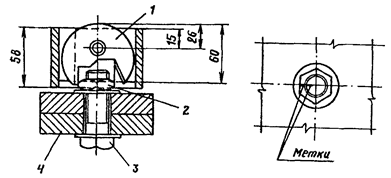
1 - punch; 2 - a nut; 3 - a high-strength bolt; 4 - package
2.3. The final tightening is carried out with a wrench adjusted at the time of tightening 1600 N⋅
m, while the nut should turn at an angle indicated in the table.
|
The number of gaps in the package |
Bag thickness, mm |
Rotation angle, degrees |
|
20-75 |
||
|
20-125 |
||
|
30-140 |
3. Calibration of wrenches by the angle of rotation of the nut
3.1. Calibration of wrenches should be performed on a special calibration package consisting of three bodies with a number of holes of at least 20.
High-strength bolts are inserted into the holes of the calibration package and tightened with a wrench until the nut stops turning. A group of bolts (calibration bolts) in an amount of at least 5 pieces. don't drag out.
The calibration bolts must be tightened manually with a mounting key with a handle length of 0.3 m to failure (initial position).
3.2. On the prepared calibration bolts, a wrench is calibrated.
3.3. The compressed air pressure is set so that when the nut is rotated through an angle of 180 ± 30 ° from the initial position, the wrench will fail.
Air pressure must be checked periodically.
Air pressure control should be carried out according to the GOST 2405-72 pressure gauge installed in the place where the wrench hose is connected to the line.
3.4. When calibrating the wrench (to monitor the angle of rotation of the nut), risks must be applied to its interchangeable head.
3.5. A wrench is considered calibrated if the angle of rotation of the nut during the tension of all bolts at the time of failure of the wrench is 180 ± 30 °.
3.6. The results of the wrench calibration must be entered in the wrench calibration log (see mandatory appendix 8).
3.7. In the event of a change in the compressed air pressure after eliminating the malfunction in the wrench, it is necessary to carry out a check calibration.
APPENDIX 3
Fire Post Equipment
|
Name of equipment |
Brief technical specification |
|
Burner GAO-60, GAO-2-72 GOST 17357-71 (1 pc.) |
Wide, multi-flame, working width 100 mm. |
|
Oxygen cylinders (3 pcs.) |
|
|
Acetylene cylinders (2 pcs.) |
|
|
Reducer balloon oxygen DKD15-65 or RKD-15-81 |
Maximum inlet overpressure - 1962⋅ 10 4 Pa; working overpressure - 78.48⋅ 10 4 Pa; throughput at maximum pressure - 23m 3 / h |
|
Reducer balloon acetylene RD-2AM, DAP-1-65 |
Maximum inlet overpressure - 245.25⋅ 10 4 Pa; working overpressure - from 0.981⋅ 10 4 Pa \u200b\u200bto 14,715⋅ 10 4 Pa; bandwidth - 5 m 3 / h |
|
Rubber-fabric sleeves for oxygen supply (GOST 9356-75) with an internal diameter of 9.0 and an external diameter of 18 mm |
Operating overpressure 147.15⋅ 10 4 Pa |
APPENDIX 4
Equipment, mechanisms and tools used for processing contact surfaces, connected elements and tensioning high-strength bolts
The vibration levels of electric and pneumatic grinding manual machines and wrenches (Table 1) do not exceed those established in GOST16519-79 (ST SEV 716-77) and GOST 12.1.012-78.
Table 1
| Name |
Brand Standard |
Appointment |
| Electric Impact Wrenches |
IE-3115A IE-3119U2 IE-3112A IE-3120A |
For tightening high-strength bolts during installation and assembly work |
| Pneumatic Impact Wrenches |
GOST 15150-69 IP-3106A IP-3205A GOST 10210-74 |
Also |
| Spanners |
TU 2838-62 |
To preassemble connections |
| Electric Grinding Hand Machines |
IE-2004UZ IE 2009 |
For stripping work |
| Electric angle grinder hand machines |
IE-2102A Sh1-175 (NRB) |
Also |
| Pneumatic Stripping Hand Machines |
IP-2104 UPCHR-1 |
For cleaning metal surfaces from rust and scale |
| Gas burners |
GAO-60 GAO-2-72 GOST 17357-71 |
For contact surfaces |
The noise levels of electric and pneumatic grinding manual machines and wrenches do not exceed those established in GOST 12.1.003-76. The vibration parameters and noise characteristics of electric and pneumatic manual machines used in the processing of contact surfaces of connected elements and for tensioning high-strength bolts are given in table. 2 and 3.
table 2
Vibration parameters
| Mark | ||||||||
|
31,5 |
1000 |
|||||||
|
Logarithmic levels of vibration velocity, dB |
||||||||
| IE-3115A | ||||||||
| IE-3119U2 | ||||||||
| IE-3112A | ||||||||
| IE-3120A | ||||||||
| IE 2009 | ||||||||
| IE-2004AUZ | ||||||||
| IE-2102A | ||||||||
Table 3
Noise characteristics
| Mark |
Geometrical mean frequencies of octane bands, Hz |
|||||||
| cars |
1000 |
2000 |
4000 |
8000 |
||||
|
Sound power level, dB |
||||||||
| IE-3115A | ||||||||
| IE-3119U2 | ||||||||
| IE-3112A | ||||||||
| IE-3120A | ||||||||
| IP-3106A | ||||||||
| IP-3205A | ||||||||
APPENDIX 5
The composition of the adhesive coating
|
Name |
Recipe |
Cooking method |
|
Epoxy polyamide adhesive |
ED-20 epoxy according to GOST 10587-76 (100 wt.h) |
A hardener and an accelerator are introduced into the epoxy resin; the resulting mixture is thoroughly mixed |
|
Hardener I-5M (I-6M) according to VTU OP-2382-65-60 (50 wt. H) Accelerator UP-606-2 according to MRTU 6-09-6101-69 (2 - 3 wt.) |
||
|
Abrasive material |
Carborundum powder of the KZ or KCh brand |
|
|
Solvent |
Acetone according to GOST 2768-79 |
APPENDIX 6
obligatory
Headquarters
_______________________________________
_______________________________________
Object name
_______________________________________
Manufacturer of structures, order no.
Journal of monitoring the implementation of mounting connections on high-strength bolts
|
date |
KMD drawing number and the name of the node, joint in the connection |
The number of bolts supplied in the connection |
Bolt certificate numbers |
The method of processing contact surfaces |
Standard tightening torque or angle of rotation of the nut |
Control results |
|||||
|
Contact surface treatment |
Number of bolts checked |
Torque Check Results |
Brand Name, Team Leader Signature |
Stamp number, signature of the person in charge |
Signature of customer representative |
||||||
Ch. installation engineer _______________________________________
Print place
assembly
the organization
APPENDIX 7
obligatory
_______________________________________
Headquarters
_______________________________________
Installation organization (trust, management)
_______________________________________
Object name
Journal 1
control calibration of keys for tensioning and control of tensioning of high-strength bolts
______________
1
The magazine is issued for all keys used when making installation connections at each facility.
During the control calibration, the journal must be kept by the person responsible for the work.
The responsible person fills out a journal after each key calibration check. The journal is kept until the delivery of the object.
|
date |
Change |
Key |
Tightening torque |
Key readings |
Signature of calibration person |
|
|
a type |
number |
|||||
In this journal __________________ pages are laced and numbered
Ch. Installation Engineer _
Print place
assembly organization
APPENDIX 8
obligatory
________________________________________
Headquarters
________________________________________
Installation organization (trust, management)
________________________________________
Object name
Journal 1
wrench calibration for tensioning high-strength bolts with force control by the angle of rotation of the nut or axial tension
________________
1
The magazine is drawn up for all wrenches used when making mounting connections at each site, designed to tighten high-strength bolts by the angle of rotation of the nut or by axial tension.
When calibrating the wrenches, the journal must be with the person responsible for the work.
The responsible person fills out a logbook after each control calibration of the wrenches.
The journal is kept until the delivery of the object.
|
date |
Change |
Overpressure of compressed air at the inlet of a wrench, Pa |
Set of plates in a tight-fitting bag |
Key for initial tension |
The angle of rotation of the nut with a wrench |
Signature of calibration person |
In this journal __________________ pages are laced and numbered
Print place
assembly
the organization
Content
1. General Provisions
2. Technical requirements
3. The content of the process
4. Acceptance rules and control methods
5. Security Requirements
Applications
1. Example of calibration of a torque wrench type KTR-3
2. Methods of tensioning high-strength bolts
3. Fire post equipment
4. Equipment, mechanisms and tools used to process contact surfaces, connected elements and tension high-strength bolts
5. The composition of the adhesive coating
6. Journal of monitoring the implementation of mounting connections on high-strength bolts
7. Journal of control calibration of keys for tensioning and control of tensioning of high-strength bolts
8. Wrench calibration log for tensioning high-strength bolts with force control by the angle of rotation of the nut or axial tension


