Engineering facilities of the native land. Kalinin NPP
When carrying out land management work, it is necessary to take into account the existing infrastructure of the area, the existing engineering structures for various purposes, and in conjunction with them correctly place the road network of local importanceby conducting a feasibility study of various options. Roads in rural areas are the most important factor and an integral part of a complex and multifaceted technological process agricultural production, and their absence or low quality is the main condition that restrains the socio-economic and demographic development of entire regions. Off-road significantly increases the cost of agricultural products.
Highway- This is a complex of engineering structures and devices designed for the safe movement of vehicles in all weather conditions.
The road must ensure the movement of vehicles with the required design speed at the lowest transport costs. The speed of the car is affected by the road conditions - strength, flatness and roughness of the road surface, longitudinal slopes, radiuses of the curves in the plan and longitudinal profile. The main elements of roads should provide the ability to move cars with high speeds: the lower the speed, the higher the cost of transportation and lower productivity of cars.
Currently, a developed network of roads has been created. Road network- the totality of all roads in the country, individual Union republics, territories, regions or regions serving all sectors of their integrated economy. The basis for compiling the network of roads are improved roads of national importance, which provide administrative, economic, cultural links between economic regions.
2.1.1 Classification of roads
In Russia, there are two classifications of roads: administrative and technical.
In accordance with the administrative classificationmotor roads (depending on the subjects of law on them) are divided into the following groups:
owned federal roads Russian Federation;
motor roads of the constituent entities of the Russian Federation (regional roads), which are their property;
municipal roads owned by municipalities;
special roads owned by legal entities.
Federal roadssubdivided into trunk and main.
To trunkthe most important roads of the country, connecting Moscow with large administrative and economic regions of the Russian Federation or such areas among themselves, are considered. All main roads have numbers.
The mainhighways of federal significance supplement the main roads and together with them form a skeletal diagram of the roads of the Russian Federation.
Regionalroads are roads located within a region (republic, territory, region) and providing communication between individual settlements in a given region.
Public roadssubdivided into urban, township and non-urban. There are also resort roads, used mainly for passenger traffic in resort areas.
In accordance with the technical classification, which is set depending on traffic intensity, all roads are divided into five categories.
To I-II categoriesthey include motor roads of national importance, the main trunk roads of republican significance, entrances from major cities to airports, river and sea ports with an average daily calculated traffic intensity: on roads of category I - more than 7000 cars, and on roads of category II with lower estimated traffic intensity - from 3000 to 7000 cars per day.
III categorythey comprise republican motor roads and the main regional roads connecting economic and administrative regions, industrial and cultural centers, transport hubs, large enterprises with traffic from 1000 to 3000 cars per day.
To IV-V categorythey include automobile roads, which in most cases have local economic and administrative significance with traffic intensity: on category IV roads - from 200 to 1000, on category V roads - less than 200 cars per day.
For each technical category of the road, certain technical standards are established, on the basis of which roads and artificial structures are designed and built on them. Such standards include the number of lanes, the width of the carriageway, the smallest radii of curvature in the plan, the largest longitudinal slopes of the road, and other standards.
According to the national economic importance, roads are divided into national, republican, regional and regional; local (district and agricultural) and departmental (industrial, forestry, etc.).
Agricultural roads. When considering the classification of agricultural roads, it is necessary to take into account the specifics of agricultural production, which is associated with the analysis of transportation carried out in order to ensure the production functions of farms and meet the cultural and domestic needs of rural residents. In this regard, in agricultural production usually distinguish between external and internal transportation.
To foreign economic transportationcarried out outside the given economy include: transportation of agricultural products from currents, farms and intermediate warehouses to procurement points or to the place of processing; delivery to the farm of various materials, machinery and equipment; import of chemical and mineral fertilizers, etc. The distance of such transportations for different regions of the country varies significantly, reaching 40-60 km for the middle lane, and 100 km on virgin lands. Cars are used as vehicles, and the speed of their movement is important to achieve the greatest possible transportation efficiency.
On-farm transportationperform within the given economy. These include: transportation to fields of organic fertilizers and seed, grain transportation from combines and current, transportation of crops to warehouses, transportation of people to and from work, food delivery to field mills, transportation of fuel and lubricants to tractor brigades. The average distance of on-farm transportation rarely exceeds 6 km. As vehicles used cars, trailers on tractor traction, self-propelled chassis, horse-drawn vehicles.
In this regard, agricultural roads by the nature of transportation and destination can be divided into external and internal.
To foreign economic roadsthey include the main roads and access roads necessary for connecting the economic center of state farms with the existing network of roads, with railways and waterways located outside the territory of this economy, with elevators, oil depots, delivery points for agricultural products, as well as with individual settlements of the region.
On foreign economic roads transported agricultural goods, goods necessary for agricultural production, as well as carry out passenger transportation. In practice, these roads are often common to several farms, as a result of which they are assigned to a common (district) network. Such roads are designed according to the standards for category IV roads. On-farm roadslocated directly on the territory of the economy. In accordance with the organization of production and the features of the improvement of rural settlements, they can be divided into the following groups:
a) roads connecting the economic center of an agricultural enterprise with its branches, teams, farms;
b) roads inside the estate itself, village roads;
c) field roads (for travel to the fields);
d) other roads (for access to currents, warehouses, etc.).
Field roadscan be divided into two groups:
1) permanent field roadsconnecting the field array with the central estates of farms and with warehouses; the directions of these roads do not change due to crop rotation, since their location is determined by the location of farm enterprises, the location of permanent field mills, currents, as well as the adopted land use system;
2) temporary field roadslaid in the circuit of a separate field array; they are characterized in that their direction may periodically change depending on changes in crop rotation fields.
On-farm roads are often located on valuable lands, so during the construction of roads the vegetative layer of soil must be removed and moved to nearby fields. After completion of construction, quarries or dumps of building soils are subject to reclamation.
When assigning a road to one or another category, the prospective traffic intensity is taken into account, counting it from the year the road was commissioned. The prospective traffic intensity when assigning a category of road is taken 20 years in advance.
Traffic intensity- the number of cars and other vehicles passing through a certain section of the road per unit of time (per day or hour). The traffic intensity changes during the day and seasons, as well as along the length of individual sections: increases near cities, large settlements, railway stations; significantly reduced at night.
When designing roads, they also take into account indicators of traffic volumes on the road - cargo turnover and cargo intensity.
Cargo turnover- the indicator of transport work during the carriage of goods, equal to the product of the mass of goods transported by the distance.
Road load- the total mass of goods and vehicles passing through this section of the road in both directions per unit time.
Road conditions significantly affect the basic performance of cars. Improving road conditions accelerates the movement of goods and passengers, changing economic relations. Road conditions affect the costs of maintenance and repair, as well as the norms of overhaul runs.
In order for the elements of the modern highway to ensure the movement of cars with calculated speeds, more sophisticated methods for the design and operation of roads are needed. Even in case of erroneous actions of the driver, the road should create safe operating conditions.
Road conditions are characterized by observing the width of the carriageway and shoulders, longitudinal and transverse slopes, creating the necessary roughness and evenness of the coating. They should provide good visibility of the road from the driver's seat with sufficient silhouette visibility in the direction of movement.
In addition to the requirements for traffic safety and the convenience of drivers and passengers, the designer must take into account environmental issues, for which purpose the legislative act “On measures to further improve the protection of nature and the rational use of natural resources” has been adopted.
In the process of implementing projects for the construction of the road it is necessary: \u200b\u200bto combine the road with the surrounding area; protect forests and ways of movement of wild animals; do not occupy valuable land under road constructions; provide for the restoration of lands occupied for temporary use; comply with sanitary standards in areas of cultural recreation; remove and preserve the vegetative layer of fertile soil on the road construction sites; provide for snow and decorative landscaping; organize the collection of water from the roadway and treatment within water protection zones; when going around settlements, provide measures to eliminate traffic noise, vibration, air and water pollution.
2.1.2 The main structural elements of the road and their purpose
Modern roads are a complex complex of engineering structures, which should ensure the operation of the road all year round, especially in spring and autumn, the movement of cars at any time of the day with high speeds and rated loads.
The road consists of the main elements: subgrade, pavement, man-made structures and road conditions.
Subgrade -road structure, which serves as the basis for the placement of layers of pavement and other elements of the road. Depending on the terrain, the subgrade is designed as embankments -massif artificially sprinkled from the ground above the surface of the earth, having the shape of a trapezoid (Figure 1, a), and in the form notches -earthworks below the surface of the earth, having a given shape and shape (Figure 1, b ).
On the sloping areas of the terrain, the subgrade is designed as half-half-dredgesby cutting with a ledge part of the natural soil using it in a half-mound.
Regardless weather conditions and the season, the subgrade must maintain its geometric shape.
The subgrade consists of: the upper part of the subgrade (working layer); embankment bodies (with sloping parts); sloping parts of the recess and the base of the recess; devices for lowering or draining groundwater (drainage); supporting and protective geotechnical devices and structures designed to protect the subgrade from dangerous geological processes (mudflows, avalanches, landslides, erosion).
The upper part of the subgrade (working layer)represents a part of the canvas, it is located on the site from the bottom of the pavement at 2/3 of the freezing depth, but not less than 1.5 m from the surface of the roadway surface. The working layer is designed together with the construction of pavement.
Figure 1 - The main elements of the road:
a - in the embankment; b - in the recess.
1
- subgrade; 2 - the base of the embankment; 3 - the body of the embankment; 4 - the upper part of the subgrade (working layer); 5 - pavement; 6 - roadway; 7 - roadside; 8 - slope of the embankment;9 - lateral drainage ditch; 10 - sloping part of the recess; 11 - drainage; 12 - groundwater level
Mound bodythe subgrade is located below the working layer and is often sprinkled on areas of high embankments using local or imported soil.
The base of the embankment isnatural soil with an undisturbed structure on which the subgrade is built, or an array of soil below the bulk layer; excavation base -soil mass below the boundary of the working layer.
Mound slope partsor notchesthey are lateral inclined surfaces that limit the artificially sprinkled earthen structure.
The subgrade includes the associated drainage structures necessary for the removal of surface water, ditches, side reserves, high-speed currents, and evaporation basins. Groundwater affects the strength and stability of the subgrade. Therefore, it is necessary to lower or intercept water by designing the drainage.
Road clothes -a multilayer structure that perceives the load from vehicles and transfers it to the soil base. Pavement consists of an upper layer (coating), a lower layer (base) and additional layers.
Road structures are constantly affected by the natural conditions of the area. Changes in air humidity, daily temperature fluctuations, the prevailing wind direction, snow depth and much more significantly affect the choice of subgrade marks and the construction of pavement. The service life of pavement depends on the strength of the materials of construction.
2.1.3 Artificial structures and their purpose
When constructing a highway on the ground, various obstacles have to be overcome: streams, rivers, ravines, ditches, dry lands, gorges, mountain ranges, existing roads and railways.
To ensure the continuous and safe movement of vehicles, artificial structures are provided: pipes, bridges, viaducts, tunnels, flyovers, viaducts, special structures on mountain roads (Figure 2).
The most common types of artificial structures on roads are pipes and bridges.
Pipeslaid in the body of the subgrade on dry land or at the intersection of small streams (the embankment above the pipes is preserved). They are designed to pass small volumes of water under the road. Pipes are also used under exits and crossings. In some cases, pipes (rectangular cross-section) are used to pass small roads under the main road. local roadsas well as cattle drives in the countryside.
Bridgeit connects sections of the road located on both sides of the river, and serves to cross a water barrier, gorges, dry lands. The bridge is interrupted by the roadbed, and the movement of cars is carried out according to the construction of the bridge, consisting of spans and supports.
Tunnelsused for laying a road through the thickness of a mountain range or under a water obstacle.
In mountainous areas, tunnels are designed through mountain ranges or along steep slopes, in the area of \u200b\u200blandslides, screes, landslides, steep mountain ledges. Underwater tunnels are laid instead of bridges.

Figure 2 - The main types of artificial structures:
a - pipe; b - bridge; in - the tunnel; g - overpass; d - viaduct; e - overpass; g - gallery; h - retaining wall.
1 - round pipe; 2 - road embankment; 3 - the foundation of the bridge; 4 - bridge span; 5 - mountain range; 6 - portal; 7 - intermediate support; 8 - prefabricated reinforced concrete wall
Overpassserves to pass cars through another road or railroad; by design it is a kind of bridge.
Viaductit is a bridge of great height, located above a deep gorge, hollow or ravine. Viaducts through narrow gorges are designed single-span due to expensive intermediate supports.
Overpasserect instead of a high embankment or to pass roads over a long length at difficult intersections of roads.
Galleriesthey are arranged on mountain roads to protect from avalanches and rockfalls, most often located on steep slopes, in places of already known snow and stone landslides. The walls of the gallery should be strong, the upper arch should have an inclined surface towards the slope. This is necessary for the free flow of snow, ice, stones through the gallery.
Retaining wallssupport the road on steep slopes in the highlands. They are arranged instead of slopes of the subgrade on steep slopes, in landslide areas, on the banks of mountain rivers, in areas of talus. Retaining walls are built of reinforced concrete, concrete and in the form of masonry.
2.1.4 Arrangement of a road for traffic and protective road structures
The arrangement of roads include technical means the organization traffic (fences, signs, markings, guides, lighting networks, traffic lights, automated traffic control systems), landscaping, small architectural forms.
Road barriers are divided into two groups:
- fencing barrier and parapet types;
- railings type, mesh.
Barrierthe fence consists of racks and a horizontal beam or profile steel tape (Figure 3, a – e).
Parapetthe fence is a reinforced concrete wall (Figure 3, g – i).
These types of fences are designed to prevent the exit of vehicles from the subgrade, the carriageway of bridges, overpasses, overpasses. The height of the fences is 0.75–0.80 m, they are installed on the side of the road along the roadway.

Figure 3 - Construction of fences on motor roads:
a, b, c - from steel profiled strips; d, d - from cables (in snow-bearing areas); e - from reinforced concrete beams; g, s, and - parapet type
The second group of fences is designed for the organized movement of pedestrians and prevent access to the carriageway of animals.
For confident driving, the driver should be oriented in the direction of the road at a great distance. Therefore, on the roadsides, guide devices are installed in the form of signal posts (Figure 4), pedestals with reflective elements.

Figure 4 - Signal columns:
a - left; b - right
To ensure traffic safety on the road and timely inform drivers and passengers, marking lines are applied and road signs are installed:
- warning signs inform traffic participants about the nature of the danger;
- priority signs are used to indicate the sequence of travel of various sections of the road;
- prohibiting - introduce restrictions on movement or their abolition;
- prescriptive - set driving modes;
- information and indicative - inform the participants of the movement about the features of movement on the road;
- additional information signs clarify or limit the operation of other road signs.
Horizontal and vertical markings are applied to road surface and support elements for bridges, viaducts, parapets, fences, borders. Together with road signs, marking significantly improves the organization of traffic.
In order to give a picturesque look to highways of all categories, landscaping is provided (Figure 5).
Gardening has a snow-protective and decorative purpose.

Figure 5 - An example of greening a road in an open area
Snow protection landscaping is a multi-row tree-shrub planting of a certain density. The design and placement of landings should correspond to the amount of snow transported to the road. Decorative landscaping consists in the picturesque arrangement of groups of trees and shrubs on the right of way or the creation of alley landings along the road.
Traffic lights are used when approaching large cities to regulate the entrance to certain lanes, at traffic control points (traffic police posts). Traffic lights are installed when moving through railway crossings, drawbridges, berths of ferry crossings.
Lighting networks provide for at intersections at the same and different levels with roads and railways, all areas and facilities for servicing drivers and passengers should also be lit.
2.1.5 Buildings and structures of road and road services
In the process of designing the main elements of roads and artificial structures, great attention should be paid to the design of a system for servicing traffic on roads.
For the organization of work on the maintenance and repair of roads, maintenance of freight and passenger traffic provide road service. For road service design administrative buildings and structures, residential buildings for workers and employees, production bases, quarries, factories, warehouses, garages.
Drivers and passengers are on the road for several hours, so they need periodic rest and meals. For this purpose, motor transport facilities are designed on roads: recreational areas, car pavilions, bus stations, motels, hotels, campsites, pavilions, canteens, shops, roadside cafes.
Recreation areas are performed away from the road with a good overview of the surrounding area, best at the edge of the forest, on the banks of a stream or lake. On such sites parking areas, a recreation area and a sanitary-hygienic area with a waste bin and toilet should be provided. There are also parking lots near roadside canteens and shops.
With the growth of intercity and suburban passenger traffic, the creation of car pavilions near settlements is required. The architectural design of the car pavilion depends on local national characteristics and climatic conditions.
Bus stations (bus stations) are usually arranged in cities and large settlements for long-distance passengers.
Motels are built on the border zone of large cities, in resort areas, as well as in places that attract a large flow of tourists. The motel has a hotel complex, garages and a parking lot, a gas station and a small service station.
In the summer, campsites operate for recreation of tourists and passengers - temporary bases from prefabricated houses or tents.
To service the rolling stock they build: gas stations, service stations, vehicle inspection sites, and washing stations.
Gas stations (gas stations) are designed to refuel vehicles with fuel, lubricants and some car care items. At the gas station there is a platform with a flyover for inspecting vehicles, minor repairs by the driver himself, and the discharge of used oil. A platform with a flyover for inspecting cars may be located in the parking area at the recreation site.
Service station (STO) performs maintenance and maintenance cars.
All these structures are designed to maintain normal road operating conditions.
For the traffic control service, traffic police checkpoints and traffic police checkpoints are being built.
2.2 Cross section of the road
2.2.1 Elements of the transverse profile of the road
Cross profileroad is called the image on a reduced scale of the section of the road with a vertical plane drawn perpendicular to the axis of the road (Figure 6). Important components of the transverse profile are the construction of the subgrade along with the drainage system and pavement. The subgrade serves as the basis for pavement. It must be strong, stable, withstand loads from rolling stock, counteract natural factors, ensure traffic safety.
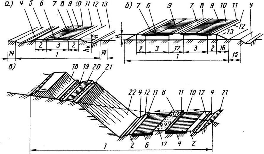
Figure 6 - Elements of the transverse profile of the road in the embankment and excavation:
a - embankment with one carriageway; b - an embankment with two carriageways and a dividing strip; in - a notch on the slope.
1 - subgrade; 2 - roadside; 3 - roadway; 4 - side ditch; 5 - external slope of the ditch; 6 - pavement; 7 - edge strip; 8 - axis of the road; 9 - axis of the carriageway; 10 - lane; 11 - the edge of the roadway; 12 - edge of the subgrade; 13 - slope of the embankment; 14 - a sawn-off shotgun; 15 - berm; 16 - the bottom of the slope; 17 - dividing strip; 18 - cavalier; 19 - upland ditch; 20 - banquet; 21 - edge of the slope of the recess; 22 - external slope of the recess; H is the height of the embankment; hk - depth of the side ditch
The upper part of the subgrade in the areas of the carriageway and curbs should have a transverse slope for quick discharge of water. The transverse profile of the road can be gable - with slopes symmetrically descending from the axis of the road to the edges of the roadbed, and gable - with a slope descending from one side of the roadbed to another.
All dimensions of the elements of the transverse profile are tied to the axis of the road. Axis of the road- a conditional line passing in the middle of the carriageway or dividing strip (for roads of category I).
Carriageway- the main element of the road on which the movement of vehicles takes place.
Depending on the traffic intensity, the carriageway can be single, double, triple or multi-lane. The width of the carriageway is measured between the edges of the pavement. It depends on the category of road and the number of lanes and is set in accordance with SNiP 2.05.02-85 “Roads”.
The edge of the roadway is a longitudinal line separating the roadway from the curb. The longitudinal lane of the carriageway along which the vehicles move in one row is lane.The lane width is set according to SNiP and ranges from 3.00 to 3.75 m.
Along the roadway on roadsides and dividing lanes edge stripsincreasing the strength of the edges of the pavement and improving traffic safety. The width of the edge strip is from 0.50 to 0.75 m.
To separate two adjacent carriageways of the road or two opposite directions of traffic, dividing strip.
Roadside- a side strip of the subgrade on each side between its edge and the edge of the roadway. The curb is designed to protect the edges of the pavement from destruction, a forced stop of the car in the event of a malfunction, the placement of stopping strips, barrier fences, and signaling devices. Roadsides can be arranged without special treatment or reinforced with local materials (gravel, gravel, slag). The width of the curb is from 1.75 to 3.75 m.
The interface line between the surface of the slope and the curb is called browsubgrade. Using this line, you can set the height of the embankment or the depth of the excavation in relation to the surface of the earth. Embankment height- the distance measured along the axis of the road from the surface of the earth to the edge line of the subgrade. The depth of the excavation is determined in the same way as the height of the embankment. In the longitudinal profile, the height of the embankment or the depth of the excavation Nare called working marks(figure 7).
![]()
a - in the recess; b - in the embankment;
1 - land mark;2 - mark the edge of the subgrade
Subway Width- the distance between the edges of the subgrade. It includes a roadway and two curbs, and for the I category of roads, a dividing strip is added.
The main parameters of the transverse profile of the carriageway and roadbed of roads, according to SNiP 2.05.02-85, are shown in table 1.
The lateral inclined surfaces of the subgrade are called slopesthat end in the side ditches.
Flat slopes allow the vehicle to exit the road without tipping over in the event of an emergency. Side ditches run along the roadbed and are designed to collect and drain surface water flowing from the roadway and the roadbed. A variety of ditches are lateral reserves - shallow workings along the road, from which the soil is used to fill the embankment. Lateral reserves are arranged on one or two sides of the road.
Table 1 - the main parameters of the design of roads

In areas where the road passes along the slope, in the embankment or in the excavation, it is necessary to provide for ditch ditchto intercept the water flowing down the slope and divert it from the road. Banquetrepresents a triangular-shaped shaft, sprinkled from the soil of the upland ditch, along the upper edge of the recess. The banquet is designed to hold water in the event of an overflow of a ditch.
A site located outside the subgrade and designed to accommodate linear buildings, sidings and bypass routes, green spaces, is called edge of the road. Minimum cutting width 1 m.
Berm- a narrow strip (platform) from the base of the embankment to the side ditch, interrupting the slope of the subgrade with a large length and steepness in order to protect the slopes from possible slipping under their own weight.
In cases where the soil from the excavation is not suitable for embankment construction, its surplus is piled away from the road in cavalierrepresenting a dump of soil of a geometric prism.
The elevation of the earth’s surface is fixed along the axis of the road and determined by leveling on the ground. The design mark of the subgrade is determined by calculation and fixed on the edge line of the subgrade. The height of the embankment or the depth of the excavation (working elevations) is determined by the difference between the design elevation and the elevation of the earth along the axis of the road (Figure 7).
The main scale of the transverse profiles of the subgrade 1: 200. A scale of 1: 100 is allowed when substantiating for difficult terrain conditions.
2.2.2 ROW
The plot of land on which the subgrade is located with pavement, artificial structures, transport and road maintenance facilities, means of registration of the road, called right of way(figure 8).
The width of the right of way for constructed and reconstructed roads is set according to the “Land allotment standards for roads” (SN 267-74) and is usually limited by the actual boundaries of the subgrade, increased by 1 m on each side. The category of road, the number of lanes, the height of the embankment or the depth of the excavation, the terrain and its transverse slope, the laying of the slopes of the subgrade.

Figure 8 - Scheme of land allocation for the road:
a - profile with ditches-reserves; b - profile with a small reserve device next to the side ditch.
1 - placement of a dump of vegetable soil during the construction of the road; 2 - distance ensuring the normal operation of earth-moving machinery; 3 - a layer of laid back vegetable soil; 4 - a layer of plant soil, removed before the construction of the embankment
The main document in the allocation and use of land for roads are the "Fundamentals of land legislation." All land is part of a single land fund and is divided by purpose: into land of agricultural importance, land of reserves, settlements, state reserves. Therefore, the right of way for the construction and operation of the road is provided for permanent or temporary use. Permanent land use of land during the operation of the road is carried out without predetermined deadlines.
The averaged indicators of land allotment areas for a road per 1 km of its length are given in table 2.
The road construction project establishes additional stripes of land allotted for permanent use. This is necessary: \u200b\u200bto accommodate drainage structures (pipes, bridges, upland ditches); a cut of soil and deforestation in order to ensure visibility in the plan; accommodation facilities for the rest of the driver and passengers, technical assistance facilities; planting of decorative plantings; facilities of the road maintenance service.
When designing roads on very valuable agricultural land occupied by perennial fruit plantations and vineyards, arable land located on irrigated or drained lands, forest shelter belts, it is not allowed to design lateral reserves and cavaliers.
Temporary use of land is carried out for the period of construction of the subgrade in the process of creating soil reserves along the road and soil pits outside the ROW.
Table 2 - Indicators of land allotment areas for a road per 1 km of its length

After completion of construction work, the right of way for temporary use is returned to a condition suitable for use in agriculture or forestry. Bringing land to a usable condition is carried out during the construction of the road. It is imperative to remove and store the fertile humus layer of soil in order to use it to restore land along the subgrade. Plant soil is stored within the right of way at its border, which is fixed by boundary signs.
End of fact sheet. Full version
| Parameter Name | Value |
| Topic of the article: | Engineering facilities |
| Category (thematic category) | Architecture |
Engineering constructions include all construction objects, except for buildings, for example, a bridge, water supply, overpass, gallery, pipeline, whatnots, water towers, etc. At industrial enterprises, engineering structures differ based on the nature of production. Οʜᴎ can be located both inside and outside industrial buildings, as well as independently of buildings, having independent significance.
Engineering structures should be distinguished from technological and engineering equipment, buildings, engineering support systems, production facilities. Unlike engineering structures in industrial buildings, the technological process is carried out to obtain the main and intermediate product of production, but they are erected, like engineering structures, by construction methods.
Technological and engineering equipment is erected in most cases by mechanical engineering methods, i.e., it is mounted from elements manufactured at enterprises of machine-building industries.
The main types of engineering structures and their functional purpose are shown in Fig. 1.17.
Supports and overpasses. Pedestals for horizontal and vertical equipment are intended for various devices in which various chemical and other processes can take place. They are most often found in the chemical, oil refining, and rubber industries, in factories of yellow concrete and plastic products. Free-standing supports and trestles for pipelines are used in those cases when industrial communications are laid in an open way.
Pipelines are used with diameters from a few centimeters to 2-3 m for gas pipelines. Pipelines of medium and large diameters are beams of cylindrical section and have a large bearing capacity, which allows them to be supported on separate supports with steps of 6-12-18 m. Pipelines of small diameters require more frequent supports, therefore it is extremely important for them to use flyovers with spans, on which transverse traverses are supported with steps of 3-4-6 m.
Pipelines can be located at three levels:
On yellow concrete sleepers laid on a sand cushion along the ground;
On low yellow concrete supports 0.9-1.2 m high;
On high yellow concrete or steel supports and overpasses with a height of 5-6 m or more.
Single-tier and two-tier freestanding supports are, as a rule, prefabricated yellow concrete. With a width of traverse up to 1.8 m, they are made single-columned T-shaped, and with a width of up to 2.4 m single-columned with separate traverses.
With a larger width, the traverse of the support is made two-post.
Multi-level supports, and in the northern and inaccessible areas - all supports, can be made of steel. The height of the supports to the top of the lower beam is taken to be 5.4; 6; 6.6; 7.2 and 7.8 m.
Typical two-tier flyovers with a span of 18 m are yellow concrete with segmented dividing trusses, with steel grating trusses resting on yellow concrete or steel columns. Temperature blocks can have a length of up to 72-75 m.
Two-tier overpasses in precast reinforced concrete are heavy, complex, and have low repeatability of elements; in this connection, such overpasses are made in most cases by steel.
Three-tier overpasses, as well as overpasses in hard-to-reach areas and overpasses with spans of more than 18 m, are made of steel.
Yellow concrete reinforced support columns are usually made rectangular, with a cross section of 400´400 mm, pinched into separate foundations, in the form of separate pile columns driven into the ground, pile columns joined into flat or spatial systems by setting up steel cross ties. Columns installed on single-pile foundations from pile-shells or bored piles are also used. With small loads and dense soils, the columns can be installed in wells drilled into the ground with subsequent concreting. Pile columns are the most economical type of support.
Posted on ref.rf
They are recommended in all cases that are permissible in soil conditions.
Columns of steel supports are made rigidly connected to the foundations. The use of articulated bearing on foundations is allowed provided that the supports are stable in the longitudinal direction.
Supports and flyovers are designed using the following regulatory and technical documents: Construction Norms and Regulations 2.09.03-85 “Structures of industrial enterprises”; GOST 23235-78. ʼʼEstacades are single-tiered for technological pipelines. Types and main dimensionsʼʼ; GOST 23236-78. ʼʼ Two-tier overpasses for technological pipelines.
Types and main dimensionsʼʼ; GOST 23237-78. ʼʼ Supports separately standing under technological pipelines. Types and main parametersʼʼ.
Unloading racks are intended for unloading various materials from railway cars, transporting materials (coal, peat, wood, sawdust) and laying pipelines.
An overpass is an open horizontal or inclined structure, consisting of a number of supports and a span, designed for laying railways, roads and pedestrian roads and communications. Flyovers for unloading various materials from railway cars can be made of their precast concrete and steel structures. Overpasses designed for laying pipelines with flammable combustible liquids and gases must have fireproof supporting and enclosing structures.
Open crane racks are intended for servicing warehouses equipped with bridge electric cranes with a lifting capacity of 10-50 tons or more. Steel crane beams are used in heavy duty cranes or with a lifting capacity of 50 tons or more.
Galleries.Galleries - a ground or elevated, horizontal or inclined lengthy structure intended for engineering or technological communications (conveyors, cable cables, pipelines), as well as for the passage of people.
The most widespread are conveyor belts and, to a lesser extent, pedestrian galleries. The passage of cables and pipelines is usually done along the way in combined galleries combined with conveyor or pedestrian ones.
The width of the pedestrian galleries is determined by their capacity in one direction at the rate of 2 thousand people. per hour per 1 m of width, but not less than 1.5 m.
The height of the galleries from the floor to the bottom of the protruding coating structures is at least 2 m (in inclined galleries, the height should be measured normal to the floor).
Conveyor (transport) galleries are used in the mining, coke and chemical industries, the industry of building materials and products, in boiler rooms and other industrial facilities. The basis of the conveyor gallery is conveyor (continuous) transport. The height of the galleries is 18, 24, 30 m. The slope of the galleries is from 1 to 20 ° based on technological requirements.
Canals and tunnels.Canals and tunnels - underground, enclosed, horizontal or inclined lengthy structures designed for laying communications (conveyors, pipelines, cables) or for the passage of people.
Channels arrange impassable, semi-pass and pass through with a passage width of at least 0.6 m. The height of the impassable channels is 0.3; 0.6 and 1.2 m, semi-aisles - 1.2-1.8 m. In channels 1.2-1.8 m high and more, hatches of 600-800 mm in size are provided, with a distance between them of no more than 60 m.
Plates covering the channels passing through the building with pipelines for flammable liquids and gases must be fireproof. Open channels placed in the workshops should be fenced along the entire long railing with a height of at least 600 mm with the device in the necessary crossing points.
The channels have a height up to protruding parts of less than 2 m, as a result of which people are not allowed into them. For inspection and repair of communications, digging and opening of channels is necessary.
The tunnels have a height of 2 m or more, allowing inspection and repair of communications during operation. They should include walkways, entrances and hatches, lighting, and, if necessary, ventilation to ensure the safety of those working in tunnels.
Tunnels and channels should be designed according to SNiP 2.09.03-85. ʼʼConstruction of industrial enterprisesʼʼ and performed, as a rule, with reinforced concrete prefabricated structures of standard designs.
The routes of tunnels and channels should have the smallest length, the least number of turns, as well as intersections with roads and other communications, and will be executed in accordance with the requirements of SNiP II-89-80. ʼʼGeneral plans of industrial enterprisesʼʼ. The tunnels and channels in which the cables are located should be designed taking into account the “Electrical Installation Rules” of the Ministry of Energy of Russia.
Bunkers and silos.Silos and silos - containers for bulk materials. The shape of the hopper depends on its purpose, layout of the structure, the required stock of material, physical properties of bulk material, type of supporting structures, etc.
Posted on ref.rf
Recommended forms of bins: pyramidal-prismatic, conical-cylindrical, chute, parabolic.
The bunkers are open and closed. Open silos are cheaper than closed ones, but they are used only for materials that are not susceptible to atmospheric precipitation and do not emit dust that is harmful to human health and the environment.
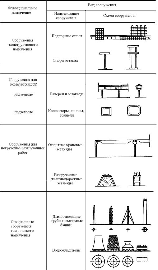
Fig. 1.17. Kinds

engineering structures
In closed hoppers with a conical coating there are no empty zones when filling. In hoppers with flat coatings, there are always empty areas, especially with a lateral arrangement of the feed opening. Empty areas not only reduce the volume of the hopper, but also pose a danger when explosive gases and dust accumulate in them.
The parameters of the bunker (shape, size and volume) should be established in conjunction with the space-planning decisions of buildings and structures, while uniform grid of columns and the height of the floors of the bunker span should be adopted. The grid of columns of bunkers is taken 6´6, 6´9, 6´12 m.
According to the type of load-bearing structures, yellow-concrete, steel and combined bins are distinguished. As a rule, bunkers are designed with yellow concrete. It is allowed to design funnels from steel, tapered parts of hoppers, parabolic hoppers, as well as hoppers, which are subject to mechanical, chemical and temperature influences of bulk material under technological conditions and are not made of yellow concrete.
When operating bunkers in an aggressive environment, their outer surfaces protect against corrosion in accordance with the requirements of SNiP 2.03.11-85. To protect the walls and bottom of the bunker from shock when loading large and medium-sized material, protective steel gratings are arranged above it. The inner surfaces of the silos, which are subject to wear from impact and abrasion, are protected by a lining of various materials. At high temperature or aggressiveness of the bulk material provide a special wear-resistant protection.
When calculating silos, the friction of bulk material on the wall surface is taken into account, which reduces the vertical pressure of the upper layers to the lower ones, which leads to a decrease in horizontal pressure. Separate silos are combined into silos, which are used as warehouses for finished products and as intermediate containers for raw materials and semi-finished products. To dedust the air leaving the silos when they are loaded, filters are usually installed on the silo coating.
Silos are not suitable for storing materials that are capable of caking, spontaneously ignite, or have a structure that breaks down at significant pressure. The dimensions of the silos, their shape, the number in the housing, as well as the layout in the plan are assigned in accordance with the requirements of the technological process, loading and unloading conditions, technical and economic considerations, as well as the unified construction parameters existing for silo warehouses. In Russia, silos are used predominantly round and square. Preference is given to round silos, the walls of which work mainly for central tension. When a large number of small silos are required to store different materials or the same material of different grades, then square-section silos are used, which are rational with side sizes not exceeding 3-4 m. Housings from hexagonal, octagonal and other sections of silos are found abroad.
Silos are free-standing or interlocked in silos and have a single or multi-row arrangement. A common arrangement of round silos is one or two rows; at the same time, the simplest mechanization of supply and shipment of the stored material is achieved.
For large volumes, as well as for the best use of the site, a multi-row arrangement of silos is used. In this case, cavities are formed between the silos - the so-called "stars" - which can be used as additional containers for storing incoherent material or for arranging stairs in them, installing process equipment and allowing various pipelines to pass through. Today, the following types of silos are used, differing mainly in bottom designs:
Flat-bottomed and plated;
With a flat bottom, a steel half-funnel and a sketch;
With a steel funnel;
With yellow concrete funnel.
In the cement industry, two-tier silos are used. In order to ensure uniformity of space-planning and structural solutions for silos, the Gosstroy of Russia approved unified construction parameters, in accordance with which the following forms and sizes of silos are recommended: round - with a diameter of 3, 6 and 12 m; square - with a grid of 3´3m. Designing of yellow concrete silos with a diameter of 18, 24 and more meters (multiple of 6) is allowed. The grid of center axes passing through the centers of the silos in the buildings must be a multiple of 3 m. The height of the walls of the silos from the bottom plate to the bottom of the silo floor slab is taken to be 10.8; 15.6; 18; 20.4; 26.4 and 30 m. Other wall heights are allowed, differing by a multiple of 0.6 m. The height of the sub-floor floor (from the floor to the bottom of the bottom plate or the yellow concrete reinforced support ring of the funnel) is assumed to be 3.6; 4.8; 6; 10.8; 14.4 meters
Columns of the storey floor with a diameter of silos up to 6 m and the arrangement of funnels for its entire diameter are installed along the perimeter of the walls of the silos. If the diameter of the silo is more than 6 m, if a flat bottom is arranged, the columns are also installed inside the silo circuit. The distance between the columns is prescribed taking into account the dimensions of the approximation of vehicles. Columns of square silos are installed in the corners of the intersection of the walls. The width of the flights of stairs, when there is an elevator for lifting people and equipment up to the silos, it is recommended to take a cleanliness of at least 0.8 m, with an incline of not more than 45 °.
In accordance with the unified construction parameters, standard разработаны Designs of yellow concrete reinforced silos with a diameter of 6 and 12 m for storing bulk materials разработаны were developed.
Metal tanks and gas holders. Metal tanks are used for storage and technological processing of oil and oil products, water, chemical products, mineral fertilizers, liquefied gases, ore pulp, coal and other liquid and semi-liquid products. The tanks are recessed, round and rectangular.
Tanks in the form of tanks of cylindrical or drop-shaped tanks are used at industrial enterprises for the closed storage of flammable liquids: oil, kerosene, gasoline, oil, alcohol, etc. Tanks and tanks are underground, semi-underground and above-ground.
The location of the fuel tanks in the master plan should be linked to the rail and by road, water and coastal devices. Vertical cylindrical tanks are constructed in three types: with a fixed roof, a fixed roof and a pontoon, and with a floating roof. Such tanks have a volume of up to 50 thousand m 3, a diameter of 4.7-60.7 m, a height of 3-18 m.
Designs of vertical tanks with a volume of 100, 120 and 150 thousand m 3 were developed. Vertical tanks with a fixed roof are intended for storing weakly evaporating products and consist of a cylindrical wall, bottom and coverings of various types (conical, spherical, “non-momentous”, etc.). The “non-momentary” coating is a shell of negative Gaussian curvature.
Similar tanks with a fixed roof and a pontoon differ from the described tank by the presence of a special design floating on the product inside the tank of the pontoon, which reduces evaporation during storage of volatile products. The pontoon moves along two vertical tubular guides, when emptying the tank, it is installed on the bottom on racks.
The space between the wall and the contour of the pontoon is sealed with a sealing valve of various types. Vertical tanks are intended for the storage of petroleum products and are widely used in oil refineries, oil pumping stations of oil pipelines.
Vertical tanks with a floating roof are designed, like tanks with a pontoon, for storing volatile products. In tanks of this type, the functions of the pontoon and the fixed roof are combined in one design, which, unlike the pontoon, is designed for weather loads. In this regard, in the floating roof there is a "water discharge" - a tubular design that provides water drainage from the roof surface outside the tank.
All vertical tanks are manufactured at specialized tank metal fabrication plants using the method of rolling walls, bottoms, central parts of floating roofs, pontoons and “non-momentary” stationary roofs.
Roof elements of other types, as well as other non-rollable structures (crown of pontoons and floating roofs, stiffening rings, etc.) are manufactured by industrial methods in the form of finished large elements. Assembling the tanks is preceded by the deployment of rolls and their installation in the design position. Tanks with floating roofs are designed to store oil. Οʜᴎ effective and applied in southern and temperate regions. Their metal consumption is on average 20% lower than the metal consumption of tanks with a fixed roof and a pontoon.
Vertical isothermal tanks, double-walled and single-walled, are designed to store liquefied gases under atmospheric pressure and at low negative temperatures (-34 o C for ammonia, -46 o C for propane, -106 o C for ethylene, -160 o C for liquefied natural gas, -196 ° C for oxygen).
In double-walled isothermal tanks, the outer casing is made of ordinary carbon or low-carbon steel and is designed for atmospheric and thermal insulation loads in the inter-wall space. The inner casing, as well as the casing of single-wall isothermal tanks, are made of cold-resistant steel grades and are designed for loads from hydrostatic pressure due to the liquefied product͵ overpressure in the vapor-air space, pressure from thermal insulation and vacuum. Isothermal tanks are fabricated at tank metal plants using the wall roll method, as well as by assembly from separate sheets.
Spherical (spherical) tanks and gas holders with a volume of 6 and 2 thousand m 3 are designed to store liquid and gaseous products at high internal overpressure from 0.25 to 1.8 MPa.
The calculation of ball tanks and gas holders is performed on the hydrostatic pressure of the liquid, overpressure in the gas space, atmospheric and other loads, taking into account the requirements of the Gosgortekhnadzor of Russia. The shell of such a reservoir (gas tank) is made of individual petals made by cold rolling. The assembly of the shell at the installation is carried out using a special manipulator or in another way. Assembly welding - automatic.
The reservoir (gas holder) is installed on tubular racks (supports) having connections between each other.
Spherical reservoirs (gas holders) are equipped with external mine ladders, internal rotating inspection ladders, and also platforms for equipment maintenance. Several such reservoirs (gas holders) are combined into parks and connected by transitional sites.
Gas storage tanks of variable volume (constant pressure) are divided into gas storage tanks with a water basin (wet gas storage tanks) and cylindrical piston storage tanks (dry gas storage tanks).
Wet gas holders consist of a vertical cylindrical tank filled with water, and one or two moving links - a telescope and a bell. In a large volume gas tank there should be several similar links.
In gas holders, there is no small amount of telescope. The change in volume is achieved by the extension of the movable links when filling with gas and lowering them back as it is spent. The pressure in the gas tank (~ 5 kPa) is supported by special weights and a mass of moving links. The tightness of adjacent links is ensured by water locks.
In dry gas tanks, the volume changes by moving the piston (washer) inside the gas tank.
Reservoirs of underground location, trench and casemate type with a volume of up to 10 thousand m 3 are intended for long-term storage of light oil products and liquid raw materials for food products.
Cooling towers, water towers. Cooling towers, spray pools and cooling ponds - facilities designed to cool water. In tower drip towers, high temperature water entering the sprinkler, falling, passes through the grate system, is crushed into droplets and cooled. Chilled water accumulates in the tank, from where it goes to production.
The main structural element of tower cooling towers is an exhaust tower. Cooling towers are made of steel and monolithic reinforced concrete. Precast concrete towers were not widely used due to possible destruction at the joints. Previously constructed low-capacity cooling towers have exhaust towers made of wood.
For small and medium-sized cooling towers, towers in the form of a spatial steel frame with a sheathing of the inner side with wooden shields or asbestos-cement corrugated sheets gained predominant distribution. All these cooling towers are pyramidal in shape, with the lower tier of the tower having a vertical arrangement. Structurally, the exhaust tower of the frame-sheathing type is a multifaceted lattice structure.
The spatial rigidity of the frame is ensured by horizontal lattice rings located along all tiers, corner struts-trusses and diagonal ties (braces) located along the inner faces of the frame. The structural solution of the frame is subordinated to the possibility of mounting the tower in enlarged blocks, equal in height to one tier, and in width - to one face of the tower. The overall dimensions of the exhaust tower are determined based on the performance of the cooling tower. So, the exhaust tower of a cooling tower with an irrigation area of \u200b\u200b1600 m 2 has a height of 54 m, the radius of the inscribed circle below 23 m, and above - 15.2 m. In terms of the tower represents a regular twelve-sided tower, and is divided into five tiers in height.
The drainage basin of tower towers is usually made of monolithic reinforced concrete. Its inner surface is protected by waterproofing (a layer of cold asphalt mastic, etc.). In “dry” cooling towers there is no drainage basin. The supporting structures of the sprinkler are made of prefabricated yellow concrete columns with a cross section of 300´300 mm with columns, crossbars of 300´400 or 300´600 mm, a span of up to 4.8 m, and beams carrying a sprinkler with a cross section of 200´400 mm.
Two types of film sprinkler are widely used in irrigation devices (on the same yellow concrete frame): a single-tier block sprinkler of wooden antiseptic parts and a two-level sprinkler of flat asbestos-pressed pressed sheets (1.6´1.2´0.06 m in size) ) Installation of metal structures is carried out by the usual method.
Yellow concrete towers usually have a single-cavity hyperboloid shape that is most rational from an aerodynamic point of view.
Given the dependence on the design of the irrigation device and the method by which the surface of contact of water with air is increased, the cooling towers are film, drip spray and mixed drip and spray types. Structurally, the drip sprinkler is made of cross rails of a special shape; film - from asbestos-cement sheets located vertically at a small distance from each other.
The direction of air movement in relation to the cooled water in the sprinklers of cooling towers should be: countercurrent (counter); transversely accurate; mixed (transverse countercurrent).
A special type of cooling tower is radiator coolers, sometimes called “dry” cooling towers. The water cooled in them transfers heat to the air passing through the cooler by heat transfer through the walls of the radiators. The advantage of these cooling towers is the complete protection of the environment from the steam emitted by all other cooling towers.
Fan cooling towers have different volumes and shapes in plan: round, square, rectangular, and polygonal. Of these, single-fan cooling towers, round and polygonal in plan, have the most plastic volume.
It is advisable to use fan cooling towers in the following cases:
If it is extremely important to reduce the area for placement of water cooling facilities or to place them on a site with adverse conditions for the movement of air (the presence of tall buildings around the tower, a significant number of windless days in the warm season, etc.);
When cooling the circulation water in a hot climate.
Cooler ponds are usually referred to as off-site facilities; other types of water coolers are placed directly on industrial sites.
Water towers - ϶ᴛᴏ structures designed to increase the pressure of water in water supply networks in the absence of pumping stations and in emergency cases, as well as to regulate water consumption. They are used in drinking water, industrial and fire water supply systems of industrial enterprises, agricultural complexes and populated areas.
The main elements of a water tower are a tank (or tank) and a support. Given the dependence of the capacity of the tank and the height of the support (to the bottom of the tank), the overall patterns of the water towers are determined. The architectural appearance of the structure depends on the shape of the tank and the support and their proportional relationship with each other.
For mass construction, as a rule, towers are used without tents, with steel tanks and supports made of yellow concrete, brick or metal.
The tank capacity is 15, 25, 50 m 3 at a support height (from ground level to the bottom of the tank) that is a multiple of 3 m, and 100, 150, 200, 300, 500 and 800 m 3 at a support height that is a multiple of 6 m. it is possible to use towers with a large tank volume.
Tanks are spherical, conical, drop-shaped, cup-shaped and other forms; trunks - from shells of a cylindrical, conical shape and hyperbolic outlines, as well as from lattice structures. Monolithic reinforced concrete and metal should be used as basic structural materials. Sometimes, based on architectural considerations, the tower is designed with a tent. Unique towers of monolithic reinforced concrete are erected using sliding formwork. The tank can be mounted on the ground with its subsequent rise to the design level.
Chimneys. Chimneys are designed to exhaust flue gases generated in industrial heat power plants.
The trunk of a brick chimney consists of individual belts in height. The transition from one belt to another is carried out by reducing the thickness of the masonry with the formation of a step on the inside of the trunk. The thickness of the walls of the trunk of the upper belt is not less than 1.5 bricks. For the perception of internal stresses from the outside of the barrel, clamping rings made of strip steel are installed.
Monolithic yellow-concrete chimneys are currently being designed up to a height of 420 m, with a lining made of light polymer-cement concrete. Gas exhaust trunks are made of steel, ceramics, plastics and other materials.
Today, there has been a trend towards the use of multi-barrel pipes. In such pipes, each industrial unit is connected to a separate gas outlet trunk, which allows repairing pipes without stopping all units.
Engineering structures - concept and types. Classification and features of the category "Engineering structures" 2014, 2015.
Presentation about Kalinin NPP.
Download:
Preview:
To use the preview of presentations, create yourself a Google account (account) and log in to it: https://accounts.google.com
Slide captions:
Pupil of the 5th “A” class of the Moscow State Educational Institution of Higher Education and Science of the city of Kalyazin Krasikov Dmitriy Head Bardina L.N.
The advantages of nuclear power plants (NPPs) over thermal (TPPs) and hydroelectric power plants (HPPs) are obvious: there is no waste, gas emissions, there is no need to carry out huge volumes of construction, to build dams and bury fertile land at the bottom of the reservoirs. Perhaps more environmentally friendly than nuclear power plants, only power plants that use the energy of solar radiation or wind, but they are low-power and cannot meet the needs of people in cheap electricity - and this need is growing faster.
Nuclear energy is one of the most promising ways to satisfy the energy hunger of mankind.
Preview:
Engineering facilities native land. Kalinin NPP.
Slide 1
Project
"Engineering facilities of the native land"
Kalinin NPP
Slide 2
Kalinin Nuclear Power Plant
Slide 3
Geographical position:
Kalinin NPP (also known as Udomel NPP) is named after the former name of the city of Tver - Kalinin. The station is located in the north of the Tver region, on the shores of Lake Udomlya, 125 kilometers from Tver. Kalinin Nuclear Power Plant is located at a distance of 260 km from the city of Moscow and 320 km from the city of St. Petersburg.
Slide 4
The atomic station in Udoml was founded in 1974. Total station
consists of four power units with VVER-1000 reactors, which were commissioned in 1985, 1987, 2005 and 2012, respectively. Total current capacity is 4,000 MW.
Slide 5
Like all nuclear power plants in the Russian Federation, it is part of the Rosenergoatom concern.
Slide 6
Kalinin NPP generates 70% of the total electricity generated in the Tver region. The nuclear power plant supplies power to the Unified Energy System of the Center of Russia and further along high-voltage lines to Tver, Moscow, St. Petersburg, Vladimir, Cherepovets.
Slide 7
Modern civilization is unthinkable without electric energy. The generation and use of electricity is increasing every year, but the “ghost” of impending energy starvation is looming before humanity due to the depletion of fossil fuels. The energy released in nuclear reactions is millions of times higher than at other stations. The advantages of nuclear power plants (NPPs) over thermal (TPPs) and hydroelectric power stations (HPPs) are obvious: there is no waste, gas emissions, there is no need to carry out huge volumes of construction, to build dams and bury fertile land at the bottom of the reservoirs. Perhaps more environmentally friendly than nuclear power plants, only power plants that use the energy of solar radiation or wind, but they are low-power and cannot meet the needs of people in cheap electricity - and this need is growing faster.
Slide 8
Accidents at nuclear facilities are the most painful issue in the operation of nuclear power plants. However, despite their severity, in general, the probability of such accidents is small. Since the advent of nuclear energy, no more than three dozen accidents have occurred, and only four cases have been the release of radioactive substances into the environment. Nuclear energy is one of the most promising ways to satisfy the energy hunger of mankind.


