Install the intermediate support along the line of the existing power line. Reinforced concrete support: main varieties and features of application
Lighting pylons and power lines have been used since the emergence of electricity and lighting everywhere. And, if at first the posts for wiring were made primarily of wood, then at present, more technologically advanced materials are used to manufacture these structures.
However, this is not surprising, since metal and reinforced concrete supports, in comparison with structures characteristic of the first half of the last century, are becoming higher, stronger and more resistant to significant loads.
Let's consider what are the features of modern lighting poles and power lines, as well as from what and how they are made.
Features of lighting poles and power lines
It is no secret that power lines are cable (buried in the ground) and overhead. Special reinforced concrete light poles have found widespread use in the installation of overhead power lines.
Reinforced concrete supports can be installed in those regions where the calculated air temperature does not fall below -55 ° C. This limitation is due to the main features of the production material. Concrete is characterized by the presence of multiple micropores and, as a consequence, the tendency to fracture during critical temperature fluctuations.
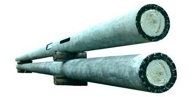
The basis of such structures is a centrifuged or vibrated stand made using dense heavy cement mortarsreinforced with welded metal structures.
Important: Structures erected using centrifuged racks are characterized by special strength and durability (they are used for the construction of 35-110 kV power transmission lines).
Power transmission towers, in addition to centrifuged and virion racks, may consist of the following structural elements:
- struts;
- prefixes;
- support and anchor plates;
- crossbars;
- anchors for fixing guy wires;
- bottom concrete cover (thrust bearing);
- a wide range of metal structures, including cable racks, traverse extensions, headband, clamps, guy wires, internal connections, attachment points.
Installation of reinforced concrete supports in the ground is carried out by installing the structure in a pre-drilled foundation pit of a cylindrical shape, followed by backfilling the sand-gravel mixture in the sinuses that have formed.
In order to provide the necessary strength of the installation of the structure on soft soils, the underground part of the OHL towers is strengthened by means of crossbars caught by half-clamps. For fastening hinged metal structures, clamps or through bolts are used.
Main characteristics
Reinforced concrete supports - are made using high-quality concrete reinforced with wire rod and reinforcing bars.
Among the main advantages of these structures, the following qualities should be noted:
- reasonable price, in comparison with all-metal analogues;
- resistance to corrosion;
- resistance to long-term exposure to chemicals;
- resistance to excessive moisture;
- resistance to temperature fluctuations.
Important: The main disadvantage of supports made using reinforced concrete is the low strength in accordance with the weight of the structure as a whole.
In addition, the high weight and dimensions of such products result in significant expenses during transportation.
Main varieties
In addition to the fact that reinforced concrete lighting poles are widely used, poles for power lines are used.
Such structures are divided into the following categories:
- Intermediate support - used in the arrangement of direct sections of the route of overhead lines.
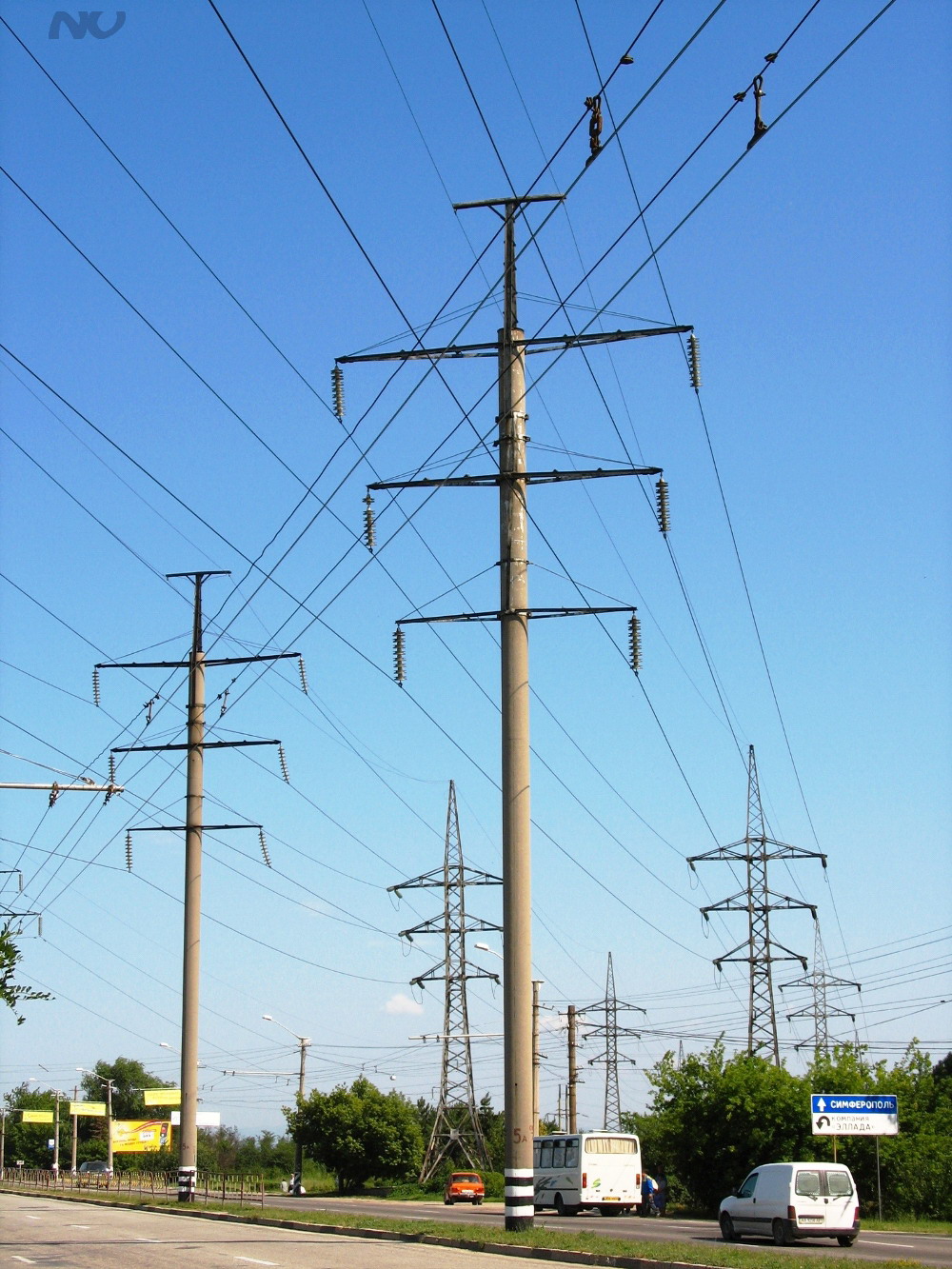
In the photo - columns of an intermediate type
Such structures are not designed for the load directed along the power transmission lines and are used exclusively for the installation of wires and fixing cables. To date, about 80% of all power lines are mounted on.
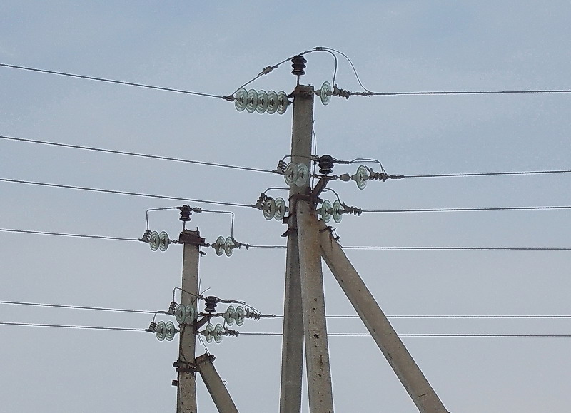
- Anchor Support used in the arrangement of direct sections of the route of overhead lines to ensure the passage through natural barriers or engineering structures. Also, these poles are widely used in those sections of the route where it is necessary to change the number, brand and cross-section of wires.
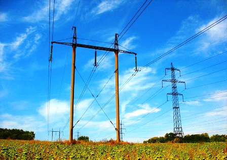
In the photo - anchor posts
- Angular support - are installed in those areas where the track changes its direction. Pillars of this type account for the resulting load of the gravity of the wires from the inter-adjacent adjacent spans.
If the track is characterized by a small angle of rotation (not more than 30 °), then the loads on the supports are small, and therefore angular intermediate supports can be used. For large angles above 30 °, angle anchor supports are used with a more robust design and wire anchoring.
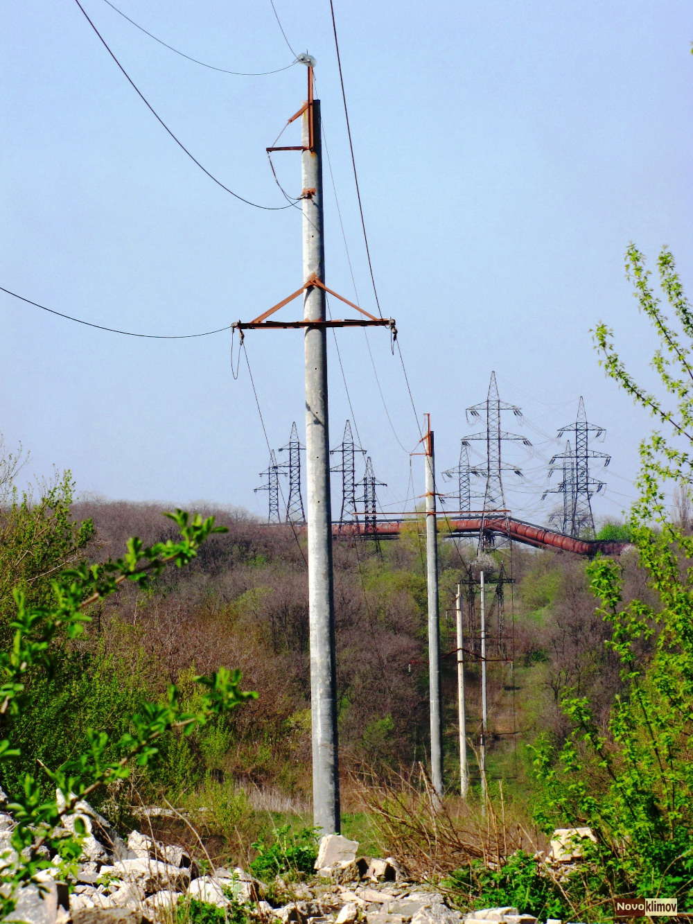
- End support - This is a kind of anchor posts.
Such structures are located mainly at the beginning and end of power lines. Structures of this type are designed for unilateral loads.
- Special Support used to perform special tasks.
Design features
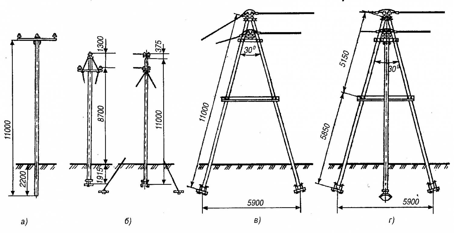
In accordance with the design features, reinforced concrete supports of overhead lines are divided into the following categories:
- gantry with guy wires;
- gantry with internal connections without braces;
- single and multi-rack with guy wires;
- single and multi-rack without guy wires.
Manufacturing technology of VL supports from concrete reinforced with metal
So, after we have decided on the technical and operational characteristics of reinforced concrete supports intended for laying overhead lines, we will consider the technology of their manufacture using the modification of CB 95 as an example.
The production instruction is phased. The first - the preparatory phase provides for the following work.
Preparation of the working mixture:
- Preparation of Portland cement, inert materials, chem. additives and water in accordance with the proportions given in the design documentation;
- Dosing of components and loading into a concrete mixer;
- Bringing the mixture to a homogeneous consistency and unloading in a paver.
Preparation of reinforcing metal structures:
- Trimming reinforcing rods of the required class into segments of the desired size;
- Preparation of anchor heads;
- The formation of contour spirals;
- Loop forming and ground rod preparation.
Cooking forms:
- Cleaning the internal volume of the form;
- Lubrication of the internal volume by means of preventing sticking of concrete;
- Distribution of spirals;
- Carrying out isothermal heating of the rods;
- Distribution of heated rods on previously laid out stops;
- Threading the spiral between the rods, followed by attaching to the rods at three points;
- Distribution of loose leaves on the ends of the form;
- Installation of tubes and process loops with their mandatory fixation to the inner surfaces of the formwork.
The second stage is production. At this stage, the working mixture is filled and the finished product is formed.
In the process, the following work is performed:
- The conveyor of the paver is installed in the working position and the pre-prepared form is filled with mortar. Form filling with concrete is carried out by moving the stacker along.
- Using a depth vibrator, the mixture is compacted to prevent the formation of voids.
- DIY workers by means of a rule or trowel level the surface of the laid material in the mold.
In the third stage, the product is subjected to isothermal treatment.
This is done as follows:
- Thermal insulating material is laid on top of the filled formwork.
- The system of heating the internal formwork volume is turned on. The system automatically controls the temperature, time, etc. Therefore, the influence of the human factor on product quality is minimal.
- Cover material is removed.
At the final stage, the mold is dismantled, reinforcement is trimmed, quality control and finished product are shipped to the warehouse.
Conclusion
So, we examined the general information about how the production of reinforced concrete supports is carried out. We also found out what these structures are, what are their technical and operational characteristics.
Still have any questions that need clarification? You can find more useful information by watching the video in this article.
Pylons are the main element of power lines. The operability and functionality of power lines, as well as the safety of their operation, largely depend on their quality and on the quality of their installation. Thus, the installation of power transmission line supports plays a huge role in ensuring uninterrupted power supply to consumers.
Installation of power transmission towers requires preliminary design work. Design should be carried out taking into account the types of supports, types of soil, terrain features and many other factors. Design work is of great importance for the quality of installation and reduce the level of costs for installation work. One of the important design stages is the calculation of the parameters of the foundation on which the installation of power transmission line supports will be carried out.
Installation of power transmission line supports is a rather complicated technological operation. A necessary condition for its implementation is the availability of specialized equipment to perform work related to lifting and moving goods, installation and high-altitude work. The level of technical equipment of the company, which carries out the installation of power transmission line supports, should ensure high accuracy of installation. The most common type of equipment for installing power transmission towers is lifting and drilling mechanisms. The stroke and reach of the crane jib should provide the ability to fully raise and hold the support in a vertical position until it is fixed to the foundation. Before fixing the supports, their position must be carefully verified vertically, the adjustment of the position of the supports is provided with the help of additional equipment. In addition, high-quality installation of power transmission line poles is impossible without an appropriate level of qualification of personnel engaged in installation works.
CB supports
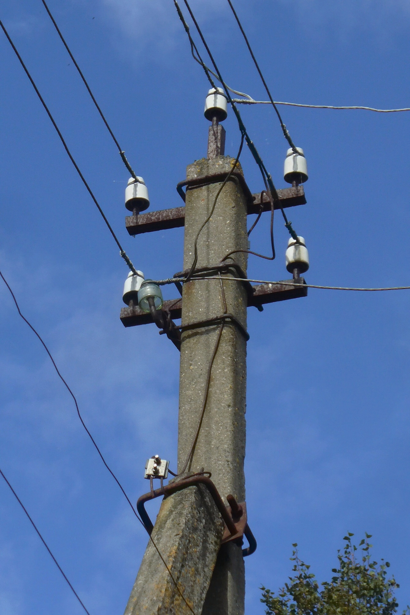
Reinforced concrete supports VL necessary to secure electrical lines to them. They hold the wires fixed to them at the desired distance from the ground. The wires themselves are fixed on supports through insulators to traverses and special consoles. Reinforced concrete has several advantages over other materials used for the manufacture of supports, such as wood or metal. Reinforced concrete is very resistant to the negative effects of the environment, is not subject to corrosion, chemicals. If the line load is from 35 kV or more, then centrifuged concrete is used. It is possible to operate reinforced concrete supports of power lines CV for more than fifty years.
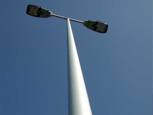
Insulator it is used for fastening and insulating suspended cables on the supports of power transmission lines SV. Insulators and other devices for fixing wires are installed on the traverse. In order to install lamps on the support that will illuminate the street, a bracket is installed at the very top of the support. This allows you to mount one or more lighting spotlights.
These structures are marked with letters and numbers.
For instance, CB 110 - 3.5 It is deciphered as follows: the stand is vibrated, its length is 11 m, and the calculated moment (maximum) is 3.5. Reinforced concrete light poles are most often installed by the letter A.
Depending on the method of suspension of wires, supports are divided into two main groups:
- intermediate supports on which wires are fixed in supporting clamps;
- anchor type supports for tensioning wires; on these supports wires are fixed in tension clamps.
These types of supports are divided into types having a special purpose.
- Intermediate direct supports are installed on straight sections of the line. On intermediate supports with suspended insulators, the wires are fixed in supporting garlands hanging vertically; on supports with pin insulators, the wires are fixed by wire binding. In both cases, the intermediate supports perceive horizontal loads from the wind pressure on the wires and the support and vertical ones - from the weight of the wires, insulators and the own weight of the support.
- Intermediate angular supports are installed at the angles of rotation of the line with the suspension of wires in supporting garlands. In addition to the loads acting on the intermediate direct supports, the intermediate and anchor-angle supports also absorb loads from the transverse components of the tension of wires and cables. At angles of rotation of the power line more than 20 °, the weight of the intermediate corner supports increases significantly. At large angles of rotation, anchor-angle supports are installed.
When installing anchor supports on straight sections of the route and suspension of wires on both sides of the support with the same tension, the horizontal longitudinal loads from the wires are balanced and the anchor support works in the same way as the intermediate one, that is, it accepts only horizontal transverse and vertical loads. If necessary, the wires on one and the other side of the support can be tensioned with different strands of wires. In this case, in addition to horizontal lateral and vertical loads, the horizontal longitudinal load will affect the support.
When installing anchor supports at the corners, the anchor corner supports also perceive the load from the transverse components of the tension of the wires and cables.
End supports are installed at the ends of the line. From these supports wires hanging on the portals of substations depart.
By appointment
Intermediate supportsthey are installed on direct sections of the overhead line, they are designed only to support wires and cables and are not designed to withstand the stress of wires along the line. Usually they make up 80-90% of all OHL supports.
Corner supports they are installed at the turning angles of the overhead line route, under normal conditions they perceive the resultant of the tensile forces of wires and cables of adjacent spans, directed along the bisector of the angle, supplementing the angle of rotation of the line by 180 °. At small rotation angles (up to 15-30 °), where the loads are small, angular intermediate supports are used. If the rotation angles are larger, then angular anchor supports are used, which have a more rigid structure and anchor fastening of the wires.
Anchor Supports they are installed on straight sections of the route for crossing over engineering structures or natural barriers, they perceive the longitudinal load from the tension of wires and cables. Their design is stiff and durable.
End supports - A type of anchor and are installed at the end or beginning of the line. Under normal operating conditions of OHL, they perceive the load from the one-sided tension of wires and cables.
Special supports:
- transpositional - to change the order of the wires on the supports;
- branch - for the device branches from the trunk line;
- cross - at the intersection of overhead lines in two directions;
- anti-wind - to enhance the mechanical strength of overhead lines;
- transitional - when crossing overhead lines through engineering structures or natural barriers.
The production of reinforced concrete supports for power transmission lines is carried out in strict accordance with the requirements of GOST. Poorly executed light support can quickly collapse, which will lead not only to financial costs associated with the restoration of a tattered section of the power line, but can also lead to tragic consequences associated with the death of people.
Assembly and installation of power transmission towers
All work on the assembly and installation of supports is carried out according to the projects for the production of work developed in accordance with SNiP 12-01-2004. Prior to the commencement of the assembly and installation of the supports, the site on which the work will be carried out must be prepared, the support elements must be delivered to it. All sites should have temporary entrances for vehicles and construction equipment.
The process of assembly and installation of supports includes: laying reinforced concrete racks and individual elements of steel supports, assembling the support, installing the support in the design position, aligning and securing it.
As a rule, the calculation of the support and its elements is carried out along the VL axis. In some cases, based on the terrain and the conditions of its rise to a vertical position, the calculation and assembly of the support is carried out across the axis of the overhead line.
On slopes, the calculation and assembly of supports must be carried out along the VL axis, with traverses in the direction of the slope rise. At the intersections of the power line with roads and railways, rivers and ravines, as well as communication lines, the supports are laid along the axis of the line, traverses and cable-resistant towards the intersected objects at a distance from the center of the support installation to the intersection of at least 1.5 of the height of the support.
This distance is considered:
- from the center of the support to the edge of the cuvette at the intersection with highways;
- with railways - to the projection of communication lines and self-locking, and in their absence - to the edge of the main subgrade;
- with ravines - to their edge;
- with rivers - to the edge of the water;
- with communication lines and overhead lines - to the projection of their outermost wire.
If during the inspection of the support before assembly separate elements of the supports are found to be damaged, then it is forbidden to proceed with assembling it before fixing and replacing these elements or parts.
Reinforced concrete support installation
Installation of reinforced concrete supports is usually carried out by jib cranes and installation cranes of supports of the KVL type. If necessary, pull up the racks using a tractor. The diameter of the cylindrical drilled pit should not exceed the diameter of the rack by more than 25%. With a larger difference, the upper crossbar is installed. Crossbars on intermediate support are located along the axis of the power transmission line.
The time between the device of the pit and the installation of the support in it should not exceed one day.
When installing two-pillar and portal reinforced concrete supports, one and the second pillars are installed in series, then the traverses, the upper ends of the cross connections between the posts and the lower ends of the cross connections are fixed.
After lifting and installing the crane free-standing supports in the excavated pits, the supports should be temporarily unfastened by guy wires, and then the lower and upper crossbars are installed. The final fixing of the supports is carried out by backfilling with soil only after they are verified by filling in the sinuses of the soil with layer-by-layer tamping. In winter, the mixture for filling the sinuses is protected from freezing by mats of slag or other heaters.


