Umbrellas. Self-repair of an umbrella How to disassemble an umbrella the machine does not close
The present invention relates to an automatic opening umbrella, in particular to a locking device for an automatic opening umbrella. The object of the invention is to provide a locking device for an automatically opening umbrella that prevents unwanted opening of the umbrella during the retraction of the telescopic central rod and has a simplified design. A blocking device for an automatically opening umbrella is claimed, wherein the umbrella contains a central rod containing an upper and lower tubes telescopically connected to each other along the longitudinal axis. The above-mentioned central rod has an upper end side and a lower end. The aforementioned umbrella also includes an upper sleeve and a handle housing fixed to the upper end side and the lower end of the central rod, respectively. The umbrella contains a slider mounted on the central rod and made with the possibility of sliding between the upper and lower positions, respectively, away and near the specified lower end. The aforementioned umbrella also includes an opening spring installed in the central rod, designed to shift the upper tube for movement from a retracted position, in which the upper sleeve is close to the handle body, to an extended position, in which the upper sleeve is distant from the handle body. The umbrella comprises a rib-and-strut system linking the top sleeve and the slider and configured to deploy when the slider is moved to the top position and folded when the slider is moved to the bottom position. The aforementioned umbrella includes a locking member for preventing the top tube from moving to an extended position by counteracting the biasing mechanism of the opening spring. Moreover, the specified blocking device contains a pull cord having a tightly fixed end, made with the possibility of moving with tension with the upper sleeve, and the first segment of the cord, which passes from the tightly fixed end to the slider and which is wound on the slider. Moreover, the first segment of the cord passes up through the upper sleeve, and then down to form the second segment of the cord, which passes into the central rod and along the direction of travel and which ends with a fixed end located in the handle body. The above locking device comprises a drum element rotatable around the winding axis in the handle body. At the same time, the end of the pull cord is fixed in such a way that the second segment of the cord unwinds when the upper tube is moved to the extended position, and winds when the tube is manually actuated to move it to the retracted position. The blocking device also includes a reel biasing spring for displacing the reel for winding the second cord segment when the top tube is manually actuated to move it to a retracted position. The above blocking device includes a push button, configured to be actuated manually to perform a pressing action relative to the body of the handle. In this case, the locking element splits and the upper tube moves to the extended position. The technical result of the invention is the creation of a locking device for an automatically opening umbrella, which prevents undesirable opening of the umbrella during retraction of the telescopic central rod and has a simplified design. 8 w.p. f-ly, 9 ill.
The present invention relates to an automatic opening umbrella, in particular to a locking device for an automatic opening umbrella.
The conventional automatic umbrella disclosed in Chinese Patent Application No. 200710009892.1, as shown in Fig. 1, includes a telescopic central rod 1, an opening spring 2 located in the central rod 1, a handle 3 fixed to the lower end of the central rod 1, a control unit 4 mounted in the handle 3, and the drive 5 fixed between the handle 3 and the central rod 1. The control unit 4 includes a drum 401, a cord 402 wound around the drum 401, a coil spring 403 and a unidirectional clamping device 404 located between the drum 401 and the handle 3. While retracting the central rod 1 to close the umbrella with the help of the coil spring 403, the cord 402 can be wound so that if the user, by pressing the central rod 1, unwittingly allows the umbrella to slip out of his/her grip, the clamping device 404 can prevent the unwinding rotation of the drum. 401, to thereby prevent undesirable stretching of the central rod 1. However, the control unit 4 has a complicated structure, so that the handle 3 is rather bulky.
It is an object of the present invention to provide a locking device for an automatically opening umbrella, which can prevent unwanted opening of the umbrella during retraction of the telescopic center rod, and which has a simplified structure.
In accordance with the present invention, a locking device for an auto-opening umbrella comprises a force-transmitting cord, a drum element, a drum-biasing spring, a push button, a unidirectional locking device, and a gripping device. The umbrella contains a telescopic central rod, an upper sleeve and a handle body, fixed respectively on the upper end side and the lower end of the central rod, a slider sliding along the central rod between the upper and lower positions for deploying and folding the rib-and-strut system, and a locking block, disposed to releasably delay movement of the top tube of the center rod to the extended position by counteracting the biasing mechanism of the opening spring.
The pulling cord has a tightly fixed end, which is moved with tension from the upper sleeve, and the first segment of the cord, which passes from the tightly fixed end to the slider and which is wound around the slider. The first cord segment further extends upward through the top sleeve and then downward to form a second cord segment which is further passed into the center shaft and along the direction of travel and which terminates in a fixed end located in the handle housing.
The drum member is freely rotatable in the handle housing and is designed such that the end of the pull cord is secured such that the second cord segment unwinds when the top tube is moved to the extended position and rewinds when the top tube is manually moved to the retracted position.
A drum biasing spring is provided to bias the drum member to wind the second cord segment when the top tube is manually pressed to a retracted position.
The push button is manually actuated to perform a push movement against the handle body to release the lock block so that the top tube can move to the extended position.
The unidirectional locking device is positioned between the push button and the reel element and is movable, in response to the pressing movement of the push button, from a locking position in which the reel element is protected from making an unwinding movement to a free rotation position in which the reel element is allowed to unwind the second cord segment .
The gripping device is located in the central rod and contains a shutter element and a locking body. The closure element is located in the top tube and overlaps the direction of travel to separate the direction of travel into a capture zone and a travel zone. The closure has an inlet which is designed to allow the second segment of cord to pass through in the normal state and which is shaped to be expandable to fit in the expanded state. The stop body is located in the movement zone when the slider is in the up position and is movable with the second cord segment so that if the slider moves from the up to the down position, the stop body is forced to push through the inlet to provide an expanded state of the inlet and accommodate in the capture zone. The retaining body remains in the gripping area after the inlet is returned to its normal state. Thus, undesirable stretching and opening of the umbrella, which may cause harm to the user or a neighboring person, can be eliminated.
Additional features and advantages of the present invention will become apparent from the following detailed description of a preferred embodiment of the present invention with reference to the accompanying drawings, in which the following is presented:
figure 1 - the handle of a conventional automatic umbrella, in section;
Fig. 2 shows an automatically deployable umbrella in a closed state, comprising a locking device in accordance with a preferred embodiment of the present invention;
Fig. 3 is a schematic view of a preferred embodiment of the present invention, on an enlarged scale;
Fig. 4 is a detailed view of a preferred embodiment of the present invention;
Fig. 5 is a sectional view of a gripping device according to a preferred embodiment of the present invention;
Fig. 6 shows an automatically deployed umbrella in an open state, in accordance with a preferred embodiment of the present invention;
Fig. 7 is an enlarged view of the preferred embodiment of the present invention when the push button is pressed;
Fig. 8 is a sectional view of an automatically deployed folded umbrella in accordance with a preferred embodiment of the present invention;
Fig. 9 is a sectional view of a gripping device, in accordance with a preferred embodiment of the present invention.
Figures 2, 3 and 6 show a preferred embodiment of a locking device in accordance with the present invention, included in an automatic opening umbrella. The umbrella typically includes a central shaft 300, an upper sleeve 500, a handle body 200, a slider 600, an opening spring 400, a rib-and-strut system 700, and a locking block.
The central rod 300 contains the upper, middle and lower tubes 330, 320, 310, which are telescopically connected to each other along the longitudinal axis. The upper and lower tubes 330 and 310, respectively, have an upper end side and a lower end as part of the central shaft 300. The lower tube 310 has a tapered support portion 340. The upper sleeve 500 and the handle body 200 are fixed to the upper end side and the lower end of the central shaft 300, respectively. The handle body 200 defines a guide rail 210 extending along a straight path parallel to the longitudinal axis. The slider 600 is mounted on the central rod 300 and is sliding between the upper and lower positions, which are respectively far and near the lower end. An opening spring 400 is installed in the center rod 300 to bias the top tube for movement from a retracted position in which the top sleeve 500 is close to the handle body 200 to an extended position in which the top sleeve 500 is removed from the handle body 200. The rib-and-strut system 700 interconnects the top sleeve 500 and the runner 600 and is designed to be deployed when the runner 600 is moved to the top position and collapsed when the runner 600 is moved to the bottom position. The locking block includes a hook hole 330 / , which is formed on the lower portion of the top tube 330, and a blocking ring 920, which is movably located in the handle body 200 for releasable connection with the hook hole 330 / to prevent the top tube 330 from moving to the extended position by counteracting opening spring bias mechanism 400.
As shown in FIG. 4, the locking device includes a pull cord 800, a drum member 10, a drum biasing spring 20, a push button 910, a unidirectional locking device 30, and a gripping device 40.
The pull cord has a tight end 801 tautly moved with the top sleeve 500 and a first cord segment 802 that extends from the tight end 801 to the runner 600 and which is wound around the runner 600. The first cord segment 802 further extends upward through the top sleeve 500 and then down to form a second cord segment 803 which is passed into the center shaft 300 and along the direction of travel and which terminates in a fixed end 804 located in the handle body 200.
The drum member 10 is freely rotatable in the handle body 200 about the winding axis, with the end 804 of the pull cord 800 secured in such a way that the second cord segment 803 unwinds when the top tube 330 is forced to move to the stretched position and winds up when the top tube 330 is manually pressed into the retracted position. The drum biasing spring 20 is designed to bias the drum member 10 for winding the second cord segment 803 when the top tube 330 is manually pressed to a retracted position.
The push button 910 is manually actuated to perform a pushing movement against the handle body 200 so as to disengage the stop block, thereby allowing the top tube 330 to be moved to the extended position. In this embodiment, the blocking ring 920 of the stop block is integral with the push button 910.
The unidirectional locking device 30 includes a ratchet wheel 31, a ratchet pawl 32, a pawl biasing element 34, a lever 33, and an actuating pin 930. The ratchet wheel 31 is mounted on and rotates with the drum element 10 and has a row of ratchet teeth 311 arranged at an angle to each other. to each other around the axis of the drum. The pawl 32 of the ratchet has a protruding driving part 323, two sliders 322 mounted on the guide bar 210 and sliding along a straight path that is perpendicular to the direction of pressing movement of the push button 910, and a stop end 321 moving relative to the ratchet wheel 31 between the locking position, as shown in Fig. 3, where the stop end 321 is engaged with one of the ratchet teeth 311 so as to prevent the unwinding movement of the drum member 10, and the free rotation position as shown in Fig. 7, where the stop end 321 is disengaged from the ratchet wheel 31 so as to allow drum member 10 to unwind second segment 803 of pull cord 800. Pawl biasing member 34 is positioned to bias ratchet pawl 32 toward the locking position. The lever 33 is hinged to the handle body about a pivot axis parallel to the winding axis of the drum member 10 and has a drive end 333 that engages with the drive portion 323 so as to move the stop end 321 of the ratchet pawl 32 from a locking position to a free rotation position, and a force-transmitting end 332 which is actuated by a pressing movement of a push button 910. The actuating pin 930 is integral with the push button 910 to be moved with it so as to transmit the pressing movement to the force-transmitting end 332 of the lever 33. In In this embodiment, the push button 910, the blocking ring 920, and the actuating pin 930 are formed as an integral switch assembly 900.
Referring to Fig.5, the device 40 capture is located in the Central rod 300 and contains the closure element 41, the locking body 45, the clamping head 43 and the tubular actuator 44. The closure element 41 is fixed in the upper tube 330 and blocks the direction of travel of the second segment 803 of the pull cord 800 for dividing the direction of travel into capture and movement zones (A, B) that are respectively near and away from the upper sleeve 500. The closure element 41 has a left and right closure halves that together define an inlet 47 allowing the second segment 803 of the cord to pass through it in the normal state, and which move away from each other radially so as to provide an expanded state of the inlet 47. Two gate springs 42 bias, respectively, the left and right gate halves 411 to move towards each other. The left and right closure halves 411 further jointly define an opening 48 which is spatially associated with the inlet 47 and which is designed to flare downwards. The lock body 45 is movably secured to the second segment 803 of the pull cord 800. As shown in FIG. The pressing head 43 is tubular for extending a pull cord 800 through it and has an engaging edge 432 which tapers towards the closure 41 and which is matingly engaged with the opening 48 of the closure 41, and a push end 433 which is opposite the engaging end 432. The tubular actuator 44 has an upper end 441 that engages with the pressing end 433 of the pressing head 43, and a lower end 442 that is positioned to butt against the stop portion 340 of the lower tube 310 when the upper tube 330 moves to the retracted position, as shown in FIG. 2, so as to generate an upward pressure force which is transmitted to the pressing head 43 such that the engaging edge 432 is pressed against the shutter member 41 so as to move the left and right shutter halves 411 radially apart, thereby providing an expanded state of the inlet 47 Head spring 46 is provided to bias engagement edge 432 away from opening 48.
When the umbrella is in the closed state, as shown in FIGS. 2-4, the top tube 330 is in the retracted position so that the locking ring 920 is engaged in the engagement hole 330/ and the rib-and-strut system 700 is folded. At the same time, the opening spring 400 is compressed, and the pawl 32 of the ratchet mechanism is engaged with one of the teeth 311 of the ratchet wheel 31, and the pull cord 800 is wound.
Consider Figs. 6 and 7. When the push button 910 is pressed, the locking ring 920 is extended from the engagement hole 330 / and the lever 33 is pivoted due to the engagement between the drive pin 930 and the force-transmitting end 332 to cause the pawl 32 of the ratchet mechanism to move to the position of free rotation. . At this point, the center rod 300 can be pulled into an extended position by the bias mechanism of the opening spring 400, and the slider 600 moves upward by pulling on the pull cord 800 and rotating the drum member 10, thereby deploying the umbrella rib-and-strut system 700. It should be noted that when the slider 600 moves to the top position, the lock body 45 moves to pass through the inlet 47 to the movement zone (B), and the inlet 47 is set in the normal state, since the lower end 442 of the tubular actuator 44 is not in contact with the support section 340 of the lower tube 310.
Consider Figs. 8 and 9. To close the umbrella, the push button 910 is pressed and the slider 600 is pulled down to the lower position so that the lock body 45 is forced to push through the inlet 47 in order to set the inlet in the expanded state, and thus placed in the area (A) capture. The retaining body 45 remains in the capture area (A) after the inlet 47 returns to its normal state. Therefore, the rib-and-strut system 700 cannot be deployed at this stage.
Referring again to FIGS. 8 and 4, when it is desired to telescopically fold the umbrella, a pressing force is applied to cause the handle body 200 and the top sleeve 500 to move towards each other. Due to the bias mechanism of the drum bias spring 20, the ratchet wheel 31 rotates to wind the pull cord 800 around the drum member 10 and strikes intermittently against the ratchet pawl 32 so as to provide audible and perceptible feedback to the user until the engagement hole 330 / in the slider 600 will not catch on the blocking ring 920 and the umbrella will be in the closed state, as shown in Fig.2. It should be noted that the inlet 47 is forced to be in an expanded state when the stopper body 45 passes during the opening of the umbrella.
During the folding of the umbrella, as shown in FIG. 8, if the user has inadvertently lost grip on the center bar 300 due to the engagement between the ratchet pawl 32 and the ratchet wheel 31, the movement of the pull cord 800 is delayed in order to hold the slider 600, the center bar 300 and rib-and-strut system 700 in place. Thus, undesirable stretching and opening of the umbrella, which may cause harm to the user or a person nearby, can be eliminated. In addition, since the lock body 45 remains in the gripping area (A) when the slider 600 is in the down position, the slider 600 can be prevented from moving to the up position so as to keep the rib-and-strut system 700 in the folded state. Meanwhile, the unidirectional locking device 30 has a simple structure in order to make the handle body 200 compact and lightweight.
Although the present invention has been described in terms of what is considered the most practical and preferred embodiment, it should be noted that this invention is not limited to the disclosed embodiment, but is intended to cover various constructions without going beyond the spirit and scope of broad interpretations and equivalent devices.
1. A locking device for an automatically opening umbrella, while the umbrella contains
a central rod (300) comprising upper and lower tubes (330, 310) telescopically connected to each other along the longitudinal axis, the central rod (300) having an upper end side and a lower end;
the upper sleeve (500) and the body (200) of the handle, fixed respectively on the upper end side and the lower end of the Central rod (300); a slider (600) mounted on the central rod (300) and configured to slide between the upper and lower positions, respectively, away from and near the specified lower end; opening spring (400) installed in the central rod (300), designed to bias the upper tube (330) to move from a retracted position, in which the upper sleeve (500) is close to the body (200) of the handle, to an extended position, in which the upper the sleeve is distant from the body (200) of the handle;
a rib-and-strut system (700) connecting the top sleeve (500) and the slider (600) and configured to deploy when the slider (600) is moved to the top position and foldable when the slider (600) is moved to the bottom position;
locking element (330"), designed to prevent movement of the upper tube (330) to the extended position by counteracting the biasing mechanism of the opening spring (400); moreover, the specified blocking device comprises:
a pull cord (800) having a tightly fastened end (801) configured to move under tension with an upper sleeve (500), and a first segment (802) of the cord that extends from the tightly fastened end (801) to the slider (600) and which is wound around the runner (600), with the first cord segment (802) extending upward through the top sleeve (500) and then downward to form a second cord segment (803) which extends into the center shaft (300) and along the direction of travel and which ends with a fixed end (804) located in the body (200) of the handle;
a drum element (10) rotatable about a winding axis in the handle body (200), wherein the end (804) of the pull cord (800) is fixed in such a way that the second segment (803) of the cord unwinds when the upper tube (330) moves to the extended position, and coils when the tube (330) is manually actuated to move it to the retracted position;
a drum biasing spring (20) for biasing the drum member (10) for winding the second cord segment (803) when the top tube (330) is manually actuated to move it to a retracted position;
a push button (910) configured to be manually actuated to apply pressure against the handle body (200), while the locking element (330", 920) splits and the top tube (330) moves to the extended position; unidirectional locking device (30) located between the push button (910) and the drum element (10) and configured to move in response to the impact of the push button (910) from the blocking position, in which the drum element (10) is protected from performing an unwinding movement, to the position free rotation, in which the specified drum element unwinds the second segment (803) of the cord; and the device (40) of the capture located in the Central rod (300) and containing
a shutter element (41) located in the upper tube (330), blocking the direction of travel to separate the direction of travel into the capture zone and the movement zone (A, B), which are respectively located near and away from the upper sleeve (500), and the shutter element ( 41) has an inlet (47) through which the second cord segment (803) passes in the normal state and which is expandable to be positioned in the expanded state, and
a stop body (45) which is located in the movement zone (B) when the slider (600) is in the upper position and moves with the second cord segment (803), the stop body (45) being formed so that if the slider (600) moves from the upper position to the lower position, the locking body (45) is pushed through the inlet (47) to bring the inlet (47) to the expanded state and is located in the capture zone (A) and the locking body (45) remains in the zone ( A) capture after the return of the inlet (47) to its normal state.
2. The device according to claim 1, characterized in that the gripping device (40) comprises a clamping head (43) having an engaging edge (432) engaged with the closure element (41) and a pressing end (433) which is located opposite to the engaging edge (432), wherein if the top tube (330) moves to the retracted position, the engagement edge (432) is pressed against the closure element (41) by an upward pressing force transmitted to the pressure end (433) to form an expanded state of the inlet (47 ).
3. The device according to claim 2, characterized in that the gripping device (40) comprises a tubular drive (44) having an upper end (441) engaged with a pressure end (433) of the pressing head (43), and a lower end (442) which abuts against the lower end of the central rod (300) when the upper tube (330) is in the retracted position to generate an upward pressure force.
4. The device according to claim 3, characterized in that the engaging edge (432) tapers towards the closure element (41) and the closure element (41) has left and right closure halves (411) which define the inlet (47) and which made with the possibility of radial movement from each other to bring the inlet (47) into an expanded state, and the left and right shutter halves (411) limit the opening (48), which is in spatial interaction with the inlet (47) and which diverges or articulates with an engaging edge (432) so that when the upward pressure force is transmitted to the pressing end (433) of the pressing head (43), the left and right shutter halves (411) move radially apart to bring the inlet (47) into an expanded state.
5. The device according to claim 4, characterized in that the gripping device (40) contains two gate springs (42) designed to shift the left and right gate halves, respectively, to bring them closer to each other, as well as the spring (46) of the head, designed to push said engaging edge (432) away from the shutter element (41).
6. The device according to claim 1, characterized in that the unidirectional locking device (30) contains
ratchet wheel (31) rotatable with drum element (10) and having a number of ratchet teeth (311) arranged at an angle to each other around the axis of the drum,
a ratchet pawl (32) having a stop end (321) and movable relative to the ratchet wheel (31) between a blocking position in which the stop end (321) is engaged with one of the ratchet teeth (311) to prevent the drum element from unwinding (10) and a free rotation position in which the stop end (321) is disengaged from the ratchet wheel (31), and
a lever (33) hinged in the handle body (200) and having a drive end (333) for moving the ratchet pawl (32) from a locked position to a free rotation position, and a force-transmitting end (332) that is activated by a pressing movement push button (910), while the drive end (333) moves the pawl (32) of the ratchet to the position of free rotation.
7. The device according to claim 6, characterized in that the unidirectional locking device (30) comprises an actuating pin (930) movable with a push button (910) to transmit a pressing movement to the force-transmitting end (332) of the lever (33), and also a pawl displacing element (34) for displacing the pawl (32) of the ratchet mechanism to the blocking position.
8. The device according to claim 7, characterized in that the lever (33) is hinged in the housing (200) of the handle, around the axis of rotation, which is parallel to the axis of winding of the drum element (10), and the pawl (32) of the ratchet mechanism is movable relative to the ratchet wheel (31) along a linear path that is perpendicular to the direction of the pressing movement of the push button (910).
9. The device according to claim 8, characterized in that the drive pin (930) is made in the form of a single unit with a push button (910), and the body (200) of the handle limits the guide rail (210) to guide the movement of the pawl (32) of the ratchet mechanism along a linear path.
A device for opening/closing an automatic umbrella contains: a rod assembly, a frame, a socket, a first slider, a second slider, a drive mechanism and a handle. The stem assembly includes a first tube and a second tube; the frame is connected to the socket and the second engine; the drive mechanism includes a screw rod and a pusher. The pusher has a drive part and an internal threaded element; the pusher is connected to the first tube by means of a connecting element, which is inserted into the second tube, and in the second tube there is a slot made along its outer wall in such a way that the connecting element moves up and down along this slot, the pusher has a drive part, a connecting part and a deformable part, wherein the deformable part is rigid in the axial direction and retains a cylindrical shape, but deforms and recovers its original shape in the torque direction. 7 w.p. f-ly, 7 ill.
Locking device for automatic opening umbrella
If you have an umbrella, but it turned out that it has become unusable, then a few tips will help you repair it.
So, it is not at all necessary to buy a new umbrella, you can repair an existing one. The weather is sometimes unpredictable, and seemingly drizzling rain can turn into a torrential downpour with gusts of wind that can make the umbrella unusable. When you finally get home, prepare everything you need to repair the umbrella. Rummage through the bins and you will surely find a couple of broken and long abandoned umbrellas, the details of which can be used.
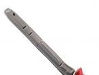
Spokes - frequent breakage
As practice shows, grooved spokes are the most frequent breakdown in modern umbrellas today.
For repair, you need to take a metal tube with a diameter of 6 mm and cut off a piece about 3 cm long from it. The tube can be a knitting needle from another umbrella, an antenna from an old TV or radio. We straighten the broken spoke of our umbrella, put our “new” prepared knitting needle on top of it and clamp it with pliers. Next, you need to put on the umbrella cover and try to open and close the umbrella several times. If the spoke does not fall out, then you did everything right and you can go out into the street in the pouring rain.
Damaged needle ends
There are also cases when the tips on the knitting needles themselves break off and the material stops holding, exposing the knitting needle. This can be dangerous for both you and those around you. The needle is thin enough and can damage the clothes of someone around or scratch, which is even worse. So, for repair, you need to take a stainless wire, thread it into a knitting needle, then stretch the fabric and twist it into a ball.
Get very original. The main thing is to twist the wire as tight as possible so that the homemade tip does not fly out under a gust of wind or from the constant opening and closing of the umbrella.
Replacing the automatic umbrella tape
The design of such umbrellas provides for a tape that can break off. But, it's not scary either. It can be repaired. To do this, unscrew the top plug of the umbrella, remove the canvas and remove the fixing nail from the top assembly. Next, you should disassemble the entire assembly by placing your hand to the open tube and removing it with great care. You need to be very careful and careful, as there is a rather tight spring inside, which can suddenly fly out and hit you in the hand. After the operations, we take out the roller and change the broken tape.
Traction failure
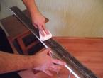
A fairly common breakdown is the failure of the thrust at the point of their hinged connection. It is worth remembering that it is possible to start repairing such a node only after loosening all connections and removing the hooks. Otherwise, you risk injury or injure someone who is nearby. We cut out a small plate about 4 * 1.2 cm in size from a piece of tinned tin and bend it along the length, thereby obtaining a small trough.
See if one of the halves of the rod is deformed. In case of deformation, it is necessary to carefully straighten it. Next, you need to tin the ends and install the overlay and do not forget to solder the repaired area along the entire length. That's it, you're done.
Retainer repair
In modern umbrellas, there is often a breakdown of the latch, which ceases to hold the umbrella closed. This problem can also be fixed. To do this, press the locking protrusion and with a sharp movement move it towards the handle. Next, you need to get the bent latch, carefully straighten it and install it back. However, if the latch is made of poor quality metal, this repair will not save you for long.
It is better to replace the latch. To do this, again, rummage in the pantry, maybe there was an old umbrella lying around with a broken needle, but with a whole latch. As described above, disassemble and remove the latch and transfer to your favorite umbrella. Next, we assemble the structure in its original form and test it. The mechanism must work properly.
As seen, repair your favorite umbrella is quite real. True, for this you need to have some skills. Not every lady will be able to cope with the task. Most people do not want to waste time and run to the shops for brand new umbrellas. However, choosing a good umbrella that will not break after two or three outings in the rain is also not a very simple task, as it may seem. However, this is a completely different story that requires separate consideration. Repairing a broken umbrella in this case will not be the most difficult way out.
Umbrella- This is a mechanical device, which is a metal or plastic frame made of knitting needles on a tubular rod equipped with a handle, on which a synthetic waterproof material is stretched. An umbrella is designed to protect a person from sunlight and rain.
The umbrella was invented in China 300 centuries ago to protect from the sun. The umbrella in those days was considered a symbol of power, and only the emperor and those close to him were allowed to use it.
Since then, a lot of time has passed, and now the umbrella has become a constant companion of any person in everyday life. The airy design of the umbrella makes it foldable and lightweight, but unstable to strong gusts of wind. Therefore, over time, everyone is faced with a breakdown of the umbrella, after which many simply throw them away.
But in vain, because you can save money and time, since usually umbrella breakdowns are simple and are associated with a rivet falling out or one of the spokes breaking. Therefore, you can repair an umbrella with your own hands using a standard tool and improvised materials in half an hour.
Repair of the articulated joint of the spokes with the rods of the umbrella
The most common failure of the umbrella is the loss of a tubular rivet from the swivel rods and spokes. From the mechanical load in the wind, the edges of the rivet unbend, it falls out and is lost.
Repair by setting as a rivet
paper clip
If the breakdown of the umbrella consists in the loss of a tubular rivet from the hinge, and there are no conditions for repair, then it can be repaired with a paper clip.

To do this, it is enough to pass the bent end of the paper clip through the holes of the knitting needle and thrust, then bend the end of the paper clip, as shown in the photo.

If you have pliers with a wire cutter function at hand, then you can take a piece of wire from a paper clip, bend it on one side into a loop, insert it into the holes and form a loop on the other side. Thus, the wire will reliably perform the function of a rivet and will not tear the fabric of the umbrella dome.
Repair by installing a homemade rivet
from copper wire
This is the most reliable repair method I've used lately. The repaired swivel in the umbrella did not have to be repaired again.

The material for the rivet is copper wire for electrical wiring with a diameter of about 1 mm. The wire is selected depending on the diameter of the holes in the rod and the spoke.

Before making a rivet, you need to pass the wire through the hole in the rod and check that it moves easily. If tight, then you need to slightly reduce the diameter with sandpaper.

Next, you need to form the head of the rivet. To do this, the wire is clamped in a vice and by hitting the edges with a small hammer, they are riveted, as shown in the photo. If the end of the wire is not flat, then you need to process it with a file with a fine notch.

When repairing an automatic umbrella, in order to be able to install a rivet, it must be kept in a half-open position, which does not allow the spring, which seeks to open the dome. In this case, use a rope to tie the movable lower clip of the umbrella to the handle, as shown in the photo.

In the next step, you need to bring the knitting needle into the slot of the thrust and insert the prepared wire with the head. Bite off the excess wire with side cutters so that its protruding part is about a millimeter.

At the last step, you need to press the created wire head to the anvil (any massive metal object will do) and flatten the wire with light blows along the edges to form a head. Here is the umbrella hinge and repaired.
As practice has shown, although an umbrella is used in wet weather, the copper rivet does not oxidize. If desired, it can be covered, for example, with nail polish.
Instead of copper wire, post nails of the required diameter can be successfully used. Nails are made from soft grades of iron and therefore also riveted well.
Umbrella joint repair with screw connection
The pivot joint of the umbrella frame can be repaired using a screw with a nut with a diameter of 1-2 mm of suitable length.

To do this, you need to align the holes of the parts coaxially, thread the screw through them and screw the nut onto it. If the screw is too long, then after tightening the nut, the protruding part must be removed using side cutters.

Usually, when biting a screw, the thread is deformed, and the screw will not be able to unscrew on its own. But for reliability, it is better to rest the head of the screw on the anvil and rivet its protruding part from the nut with a hammer.
If there is only a screw, but no nut, then you need to shorten its threaded part to the desired length and slightly rivet the protruding part.
If at least one rivet fell out of the hinge, then, for sure, the others also weakened. Therefore, in order not to repair the umbrella again in the near future, you need to tap with a hammer, resting on the anvil, all the other rivets.
Repair of spokes and rods of an umbrella
The second reason for the frequency of breakage of umbrellas is the breakage of fiberglass spokes or lugs on the rods.
Broken spoke tip repair
In this umbrella, the end of the tip of the needle broke off at the place where the hole for attaching the fabric of the dome passed. Most likely from hitting the umbrella on a hard surface.

On the left in the photo is a whole tip, and on the right is a broken one. If you have a new needle or tip, it is easiest to replace. But the spare spoke was not available and therefore had to be repaired.

For repair, a hole with a diameter of about 1 mm was drilled in the tip and sharp edges were turned with a file in the place of its breakdown. To avoid fraying the thread at the exit from the hole, it is necessary to chamfer with a larger diameter drill or a knife blade.

Repairing an umbrella with a broken fiberglass spoke
As a rule, the spokes and rods in umbrellas are made of metal, but recently umbrellas with plastic rods and fiberglass knitting needles have begun to appear.

Just such an umbrella got into repair, in which one of the spokes broke off at the point of entry into the rocker of the hinge. The rest of the spoke remained inside the hinge.

In the yoke, the spoke is fixed with the help of its bent edges. To remove the rest of the spoke, you need to slightly bend the petals with a thin blade of a flat screwdriver to the sides.

The broken end of the spoke fluffed up a little, so before fixing it in the yoke, it was smeared with Moment's quick-drying waterproof glue.

After crimping the spokes with petals in the yoke, the umbrella began to look like new. Using the same technology, repairs are made in case of breakage of the needle at the tip.
After the repair, the spoke became a little shorter, but visually, with the open dome of the umbrella, this was imperceptible.

If the fiberglass spoke broke in the middle, then its integrity can be restored using a piece of thin-walled metal tube taken from the telescopic antenna of an old radio. The broken ends of the spokes are lubricated with glue and inserted into the tube so that the junction is in the middle of the tube.
Rod eye repair
If the eyelet in the rod is broken off, then it seems that it is impossible to repair the umbrella without replacing the entire rod. But it's not. With the help of a metal knitting needle from an old umbrella, you can successfully restore the eyelet.

The photo on the left shows a working swivel, and on the right with a broken eye on the rod.

To repair, you need to take a metal knitting needle about ten centimeters long with a hole at the end from an old umbrella and tin it along the entire length with solder using an electric soldering iron.

Next, you need to remove the rivet from the rod and cover the inner surface of the rod groove with solder, as shown in the photo. When working with a soldering iron, it is necessary to exclude the contact of heated parts and its tip with the fabric of the umbrella dome, since the synthetic material may melt.

In the next step, you need to place a spoke in the groove of the thrust and heat it with a soldering iron along its entire length until the solder melts both on the spoke and in the groove of the thrust. In this case, one must not forget, and correctly orient the hole on the spoke. Using this technology, it is possible to successfully repair broken rods in the middle.

After installing the rivets using one of the technologies described above, the repair of the umbrella can be considered complete.
Umbrella hat repair
Rarely, but it happens that the decorative hat, mounted on top of the umbrella dome, breaks off or unscrews and is lost.

A cap that has broken off from the threaded part, if present, is easy to repair by restoring its integrity.

To do this, you need to drill a hole in the center in the threaded part of the cap remaining in the cane of the umbrella, with a diameter equal to the inner diameter of the thread of the self-tapping screw.

In the center of the cap, you also need to drill a hole with a diameter equal to the external thread of the self-tapping screw. Pass a self-tapping screw through the hat and grease it so that it does not unscrew with any waterproof glue and screw it into an umbrella.

The photograph shows an assembled umbrella repaired by oneself using the technology described above. The fabric of the dome is now securely fixed and water will not get on the frame parts.

If the hat is unscrewed and lost, then you can restore it with a self-tapping screw with a large press washer.

To do this, you need to make a cork from wood. A shortened furniture dowel can fit in diameter, as shown in the photo.


At the next step, a hole is drilled in the center in the cork with a diameter equal to the inner diameter of the self-tapping screw.

It remains only to lubricate the thread of the self-tapping screw with waterproof glue and screw it into the cork. As you can see, it turned out beautifully.
If a self-tapping screw with a wide head is not available, then a round washer can be cut out of a sheet of plastic of a suitable color and fixed to the dome. The washer can be made from any cork from a plastic bottle by removing the threaded part.
About the repair of automatic umbrellas
The repair of automatic umbrellas is not considered in the article, since it is very laborious and a home master without repair experience cannot afford it. It is necessary to completely disconnect the material of the dome from the metal structure, remove the upper clip, get to the roller and replace the tape. When assembling, a special tool is required to compress a fairly powerful spring. Therefore, if the opening mechanism in the automatic umbrella fails, then it is better to contact the workshop or buy a new umbrella, leaving the broken one for spare parts.
An umbrella serves as an indispensable accessory in rainy weather, protecting from water and wind. If, after another bad weather, it has lost its attractiveness or one of its main parts has broken, do not despair and do not rush to throw it away. It can always be fixed! Before repairing an umbrella, study its device, determine whether it is possible to repair a faulty spare part. Sometimes for automatic designs, the help of a specialist may be needed.
Types of umbrellas
There are varieties of designs and differences between folding mechanisms from each other. The most important part of any umbrella is a dome, consisting of a metal frame or plastic spokes, on which fabric is stretched and a solid or folding handle. Each model can be equipped with a simple or automatic mechanism. All umbrellas are conditionally divided into:
- canes- have an enlarged dome made of dense fabric, a strong handle;
- folding- structures have a telescopic device, can be folded - reduced in size (from two to five times).
Depending on the opening mechanism, there is a division into the following types:
- mechanical- open and close by hand, there are no buttons on the handle;
- semi-automatic- open manually, the automatic mechanism closes the dome when you press the button, and the handle stem folds by hand;
- automatic- the button opens the dome, and you need to close it with your hand;
- full automatic- a button is used to open and close, no effort is needed.
Device
In different models, the designs are different, but there are basic details for all umbrellas. Main elements:
- fabric stretched over the frame;
- a rod consisting of telescopic parts of the tube;
- handle, with or without button;
- lower support for spokes;
- upper supports to which the main dome is attached;
- springs (thick short and thin long);
- a wheel fixing the lower supports is built into the upper part of the plastic tube (holder).
The most common malfunction is when automatic umbrellas lose their rigidity. This happens when the wind turns them inside out, bending the thin needles. It is important to periodically check the joints of the knitting needles and, if necessary, strengthen the weakened fabric. For all umbrellas, a single rule applies: the fewer connections on the rod and spokes, the less often the structure breaks.
Spare parts
No matter how expensive and high-quality an umbrella is, it cannot be insured against breakage. Before you throw away your old one and buy a new one, try repairing your umbrella. If you have a second - unnecessary copy - then it can become a source of improvised materials for recovery. Urgent repair of umbrellas, if necessary, can be carried out by professional craftsmen in specialized modern institutions, such as the House of Life.
The following components are subject to replacement and repair:
- telescopic the stem or base of a cane;
- knitting needles from various materials;
- pen any configuration;
- dome material;
- safety spoke tips;
- central cap;
- buttons.
Do-it-yourself umbrella repair
Depending on the cause of the malfunction, prepare the necessary materials and auxiliary tools. This can be a finished part from an old umbrella, round-nose pliers, wire, or a tool for soldering metal parts. At home, you can repair the automatic umbrella with your own hands, eliminate the following breakdowns:
- damaged fabric at the seam;
- flying tip of the knitting needle;
- bent and broken spokes;
- bad latch.
Fabric repair
To connect the seam on the dome, select the threads of the appropriate color: carefully, manually, sew up the fabric. If the material has come off the end of the needle, then wrap the edge with a thin fishing line and fix it with a knot. Pass the ends of the fishing line through the hole in the knitting needle and fasten it to several knots. This procedure is performed with a free location of the fabric on the frame.

spoke repair
How to repair an umbrella if the spokes are damaged? Follow the step by step instructions:
- First, detach the fabric from the frame of the product, remembering the location of the material.
- Next, you need to straighten the damaged knitting needles. If the part is unusable, it must be replaced. Use a soldering iron for fastening or fix the metal parts of the knitting needle with wire (you can use a piece of paper clip).
- Upon completion of work, fix the material with a fishing line to the frame.
Holder repair
If the umbrella does not hold open, try to fix the product yourself. Such a breakdown is easily eliminated if the latch is bent. To do this, press the protrusion and sharply move the part to the side. This way the latch tab is taken out and gently straightened. Install it back the same way. Please note: if spare parts for umbrellas are of poor quality, then such repairs will not last long. In this case, you just need to replace the damaged part. It can be taken out of an old umbrella and inserted into the handle.
Automatic umbrella repair
Repairing an automatic umbrella is a little more difficult than a mechanical one, and it takes more time. Sometimes a breakdown is associated with improper use of the product, then the parts are severely deformed and they can only be replaced with new ones. If the machine itself is faulty, it is better to contact the masters in specialized institutions where umbrellas are repaired. This process is carried out in a short time.
Where to repair an umbrella
Repair of damaged products of any complexity is carried out by specialized workshops or stores that provide repair of shoes and clothes. In large cities, such as Moscow, St. Petersburg, there are service centers that provide high-quality repair of umbrellas. In small towns, there are also centers where the service will cost even cheaper. Pay attention to ads on the Internet, in newspapers, read reviews, customer recommendations, compare prices.

Umbrella repair price
Approximate cost of repair in Moscow:
Video
What is better for rainy weather than a bright umbrella? Nothing lifts your spirits like a new purchase!


All umbrellas that fold can be divided into the following types:
- a mechanical umbrella is endowed with the simplest mechanism, and you have to open and close it yourself;
- semi-automatic umbrella has an automatically opening dome, which is triggered by pressing a button, but you have to close it manually;
- full automatic umbrella has the most convenient and simple use, because the canopy of such an umbrella will open and close automatically, just by pressing a button.


Let's take a look at the benefits of the most popular full-automatic umbrella, and determine why it deserves such widespread use.
Men's umbrellas are mostly inconspicuous colors, such as black, blue, gray, brown. You can also see umbrellas with a checkered ornament, which are perfect for any style of clothing. For frequent travelers, a 2-fold automatic umbrella with a strong handle and automatic opening will become a convenient model. Young people prefer unisex umbrellas, they are distinguished by a wide range of colors and patterns. It should be noted that the automatic umbrella will be a wonderful gift for a man.


Think automatic umbrellas are less durable than the cane model? It's a delusion. Modern technologies make it possible to produce umbrellas with a probability of breakage tending to zero. Feel free to choose an automatic umbrella, trusting your taste!


Mom will stop worrying when the baby has a fully automatic umbrella. After all, he will always help out in rainy weather a child who is not so easy to use a mechanism that requires self-closing. An umbrella that opens and closes with a simple push of a button, a godsend available to modern society! By giving a child an automatic umbrella with a cheerful pattern, there will be no trace of sadness on the child's face in rainy weather.
Umbrella full automatic - the perfect solution! Easy to use, small, lightweight. The child will learn to use it instantly! A small bright umbrella is so convenient to hang in the wardrobe on a hanger or put in the side pocket of a briefcase.

Choosing the Right
Before heading to the store to buy an umbrella, open your closet and see what style the main part of the wardrobe is. After all, umbrellas are produced in a variety of models and fashion trends. You can see ruffles on umbrellas, and sewn on animal ears, and umbrellas sewn from combined materials, including various oilcloth details. Not uncommon will be the presence of embroidery, colorful patterns, decorations from ribbons. We can safely say that an umbrella in the modern world serves as a fashion accessory.


So, you have decided on the umbrella model and its color scheme. The choice of automatic umbrellas is so huge that the eyes run wide and it is difficult to make a choice. There are various doubts about its structure.

In the store, be sure to press the button several times so that the umbrella works for each command, check the operation of the entire mechanism and, in particular, automation.


When you press the button, the automatic umbrella should completely spread the canopy, pull the spokes tightly. When pressed again, it should automatically close.

Automatic umbrellas are equipped with a spring that protects the dome from self-opening. Poorly stretched fabric that is attached to the knitting needles? It is better to refuse to purchase such an umbrella.


Give preference to the following fabrics: polyester, rubberized satin, twill, any other fabrics with a water-repellent coating. Umbrellas with the inscription "bubble" are made of polyvinyl, a material similar to the film. This list is only a small part of what you can find on the shelves in stores. The fabric from which umbrellas are made must not let water through and be durable in strong winds. Teflon-coated fabrics dry quickly due to their water-repellent properties.
In the manufacture of the cheapest umbrellas, nylon is used; silk and cotton can be found in the fabrics of expensive umbrellas. Umbrella, the dome of which is covered with a soft shiny fabric, is made of twill.

Umbrellas for sun protection are made of satin, silk, satin, chiffon, linen. It makes no sense to walk in the rain with such an umbrella, because it does not have water-repellent characteristics.


The spokes, which are made of an aluminum frame, are less durable, but the umbrella itself is lighter. The strongest are titanium-coated steel spokes. Spokes made of carbon fiber have become widespread. Such an umbrella practically does not break, the spokes can be bent without violating the integrity of the structure.


An important role is played by the automatic umbrella locking system, which prevents sudden opening. If drops of water get into the automatic mechanism, it may cause premature failure of the umbrella.

Design matters
In modern society, we are used to using light umbrellas. The umbrella industry strives every year to introduce lighter models to consumers. The spokes are made from such materials so that the umbrella is as light as possible and at the same time durable.


There are several weight groups of umbrellas:
- weight less than 200 grams - the lightest umbrella
- 201 to 300 grams - lightweight;
- 301 to 500 grams - average weight;
- 501 to 1000 grams - heavy.
Automatic umbrellas have the ability to fold to the most compact size. They are convenient for daily carrying in a handbag, school bag or women's backpack.

The largest in size is considered the dome of the automatic umbrella with two additions of spokes. Umbrellas in 3 additions are the most popular. But umbrellas in 4 additions will be small in size and they are considered to be rightfully lightweight. The lightest umbrellas today - in 5 additions.


The lighter the automatic umbrella, the smaller the size of the canopy. This should be remembered when buying.

You will find three and two-stage addition in most women's and men's automatic umbrellas.

Umbrellas of various designs can have from six to twenty-four spokes. The construction is stronger than more spokes in an umbrella. Automatic umbrellas with 24 spokes are the most durable and, accordingly, their price is higher. Most umbrellas with 24 spokes are walking sticks.


Below are a variety of automatic umbrella handles.
The design of the handles of automatic umbrellas is very different. You can find handles of very small sizes, square, rectangular or spherical shapes. Most models have a drawstring for convenience. With the help of a cord, you can carry an umbrella on your hand.


Manufacturers
Folding automatic umbrellas are made by all major companies specializing in the manufacture of umbrellas. Companies Fulton And Zest known for their traditional English quality umbrellas. A well-known Japanese manufacturer "Three elephants", which has been popular on the Russian market for many years and annually pleases consumers with interesting models. Talk about the German quality of company umbrellas Dolphin does not take long. These umbrellas are of high quality, durable, comfortable, modern design! The smallest umbrellas - automatic machines are manufactured by a German company Knirps. Umbrella manufacturers are working on the creation of men's, women's and children's models. And strive to maximize the satisfaction of the requirements of the most demanding customers!


What to do if it doesn't work out
First of all, don't worry too much. Anxiety will not help to quickly deal with the problem! Consider carefully the simplest umbrella design scheme and it will immediately become clear to you how to cope on your own in case of any breakdown of the automatic umbrella.

Often, due to the most minor breakdowns, many throw away an umbrella. Although a completely inexperienced and without special skills person can fix the problem on his own.

Most often, the rods break, in the figure they are marked with the letters A, B. More often, the breakdown occurs in the rod A, because when the umbrella is opened, it carries the greatest load. When the rod breaks, the power spring compression hook is immediately lost. Remove stress from the frame and repair the traction is not difficult. Rest the umbrella on any vertical surface, compress the power spring by lowering the umbrella fixation sleeve.

Loosely disconnect all hooks from the rods.
For children's umbrellas of full automata, it happens that it stops returning to its original position. This is due to the fact that the protrusion of the latch hook could change its shape or break. If the integrity of the protrusion of the latch is violated, the umbrella will no longer fold. And this breakdown cannot be eliminated on your own, in the umbrella repair service you will be offered to replace the failed latch with a new one. But if the latch has not changed its geometric shape, it is enough to press the locking lug, lower the lug towards the handle, and bend the latch. Such measures will help extend the life of the latch, but soon be prepared for the next bending of the latch lug. Therefore, we recommend that you purchase a high-quality latch in advance or make it yourself from improvised materials, for example, from wire or any soft metal.

To repair more serious damage, special tools are required, which are available from umbrella repair services. Therefore, you should look at the warranty card for the product. Manufacturers give a guarantee of at least 6 months. In the event of a warranty case, you will be repaired free of charge or a broken umbrella will be replaced with a new one.

Warranties do not include:
- Scratches or dents on the handle;
- Chipped handles;
- Cuts on the fabric of the dome;
- Burnt places on the dome;
- Bent rod;
- Any damage due to mechanical impact on the umbrella.
Remember that the umbrella is repaired in specialized services. The addresses of such services can be recommended by the seller of umbrellas. Various manufacturers of umbrellas also use various structural elements, such as a spoke, a rod, a handle, a cap, and others. Not always a part from one umbrella will fit another, therefore, you will not always be able to fix the breakdown yourself. If the umbrella is dear to you, and you are not ready to change it, do not hesitate to contact a specialized repair service!