What is a servo drive, servo control. Description of the device and the principle of operation of the servo drive Servo motor control
This article discusses servos: their device, purpose, servo control, servo connection, types of servos and their comparison. Let's get started and start with what a servo is.
The concept of a servo
A servo drive is most often understood as a mechanism with an electric motor, which can be asked to turn to a given angle and hold this position. However, this is not a complete definition.
To put it more fully, a servo drive is a drive with control through negative feedback, which allows you to accurately control the movement parameters. A servo drive is any type of mechanical drive that includes a sensor (position, speed, force, etc.) and a drive control unit that automatically maintains the necessary parameters on the sensor and the device according to a given external value.
In other words:
The servo drive receives the value of the control parameter as input. For example, the angle of rotation
The control unit compares this value with the value on its sensor
Based on the result of the comparison, the drive performs some action, such as turning, accelerating or decelerating, so that the value from the internal sensor becomes as close as possible to the value of the external control variable.
The most common are servos that hold a given angle and servos that maintain a given speed of rotation.
A typical hobby servo is shown below.
How are servos arranged?
Servo device
Servo drives have several components.

Drive - electric motor with gearbox. To convert electricity into mechanical rotation, you need electric motor. However, often the speed of rotation of the motor is too high for practical use. Used to slow down the speed reducer: a mechanism of gears that transmits and converts torque.
By turning the electric motor on and off, we can rotate the output shaft - the final gear of the servo, to which we can attach something that we want to control. However, in order for the position to be controlled by the device, feedback sensor - encoder, which will convert the steering angle back into an electrical signal. A potentiometer is often used for this. When the potentiometer slider is turned, its resistance changes, proportional to the angle of rotation. Thus, it can be used to set the current position of the mechanism.
In addition to the electric motor, gearbox and potentiometer, the servo drive has an electronic filling that is responsible for receiving an external parameter, reading values from the potentiometer, comparing them, and turning the motor on / off. She is responsible for maintaining negative feedback.
There are three wires going to the servo. Two of them are responsible for powering the motor, the third delivers a control signal that is used to set the position of the device.
Now let's see how to control the servo externally.
Servo control. Control signal interface
To indicate the desired position to the servo, a control signal must be sent along the wire intended for this. Control signal - pulses of constant frequency and variable width.

The position that the servo should take depends on the length of the pulses. When a signal enters the control circuit, the pulse generator in it produces its own pulse, the duration of which is determined through a potentiometer. Another part of the circuit compares the duration of the two pulses. If the duration is different, the electric motor is turned on. The direction of rotation is determined by which of the pulses is shorter. If the pulse lengths are equal, the electric motor stops.
Most often in hobby servos, pulses are produced at a frequency of 50 Hz. This means that a pulse is emitted and received once every 20 ms. Typically, a pulse duration of 1520 µs means that the servo should take the middle position. Increasing or decreasing the pulse length will cause the servo to turn clockwise or counterclockwise respectively. In this case, there are upper and lower limits of the pulse duration. In the Servo library for Arduino, the default pulse lengths are 544 µs for 0° and 2400 µs for 180°.
Please note that on your particular device, the factory settings may be different from the standard ones. Some servos use a pulse width of 760 µs. In this case, the middle position corresponds to 760 µs, in the same way as in conventional servo drives the average position corresponds to 1520 µs.
It is also worth noting that these are just generally accepted lengths. Even within the same servo model, there may be a manufacturing error that causes the operating range of pulse lengths to be slightly different. For precise operation, each specific servo must be calibrated: through experiments, it is necessary to select the correct range that is specific to it.
What else is worth paying attention to is the confusion in terminology. Often the way to control servos is called PWM / PWM (Pulse Width Modulation) or PPM (Pulse Position Modulation). This is not the case, and using these methods may even damage the drive. The correct term is PDM (Pulse Duration Modulation). In it, the length of the pulses is extremely important and the frequency of their appearance is not so important. 50Hz is the norm, but the servo will work correctly at both 40 and 60Hz. The only thing to keep in mind is that with a strong decrease in frequency, it can work in jerks and at reduced power, and with a strong increase in frequency (for example, 100 Hz), it can overheat and fail.
Servo Specifications
Now let's figure out what servos are and what characteristics they have.
Torque and turning speed
First, let's talk about two very important characteristics of a servo: torque and about turning speed.
The moment of force, or torque, is a vector physical quantity equal to the product of the radius vector drawn from the axis of rotation to the point of application of the force by the vector of this force. Characterizes the rotational action of force on a rigid body.

Simply put, this characteristic shows how heavy a load the servo is able to keep at rest on a lever of a given length. If the torque of the servo is 5 kg × cm, then this means that the servo will hold a 1 cm long lever on the weight in a horizontal position, on the free end of which 5 kg are hung. Or, equivalently, a lever 5 cm long, from which 1 kg is hung.
Servo speed is measured by the amount of time it takes the servo arm to rotate 60°. A characteristic of 0.1s/60° means that the servo turns 60° in 0.1s. From it it is easy to calculate the speed in a more familiar value, revolutions per minute, but it so happened that when describing servos, such a unit is most often used.
It's worth noting that sometimes a trade-off has to be made between these two characteristics, as if we want a reliable, heavy-duty servo, we have to be prepared for this mighty rig to turn slowly. And if we want a very fast drive, then it will be relatively easy to unbalance it. When using the same motor, the balance is determined by the configuration of the gears in the gearbox.
Of course, we can always take a plant that consumes more power, as long as its characteristics meet our needs.
Form Factor
Servos vary in size. And although there is no official classification, manufacturers have long adhered to several sizes with a generally accepted arrangement of fasteners. They can be divided into:
small
standard
They have the following characteristic dimensions:
There are also so-called “special-type” servos with dimensions that do not fall into this classification, but the percentage of such servos is very small.
Internal interface
Servo drives are either analog or digital. So what are their differences, advantages and disadvantages?
Outwardly, they are no different: electric motors, gearboxes, potentiometers are the same, they differ only in internal control electronics. Instead of a special analog servo chip, the digital counterpart can be seen on the board with a microprocessor that receives pulses, analyzes them and controls the motor. Thus, in the physical version, the difference is only in the way the pulses are processed and the motor is controlled.

Both types of servo take the same control pulses. The analog servo then decides whether to change the position and sends a signal to the motor if necessary. This usually happens at a frequency of 50 Hz. Thus, we get 20 ms - the minimum reaction time. At this time, any external influence can change the position of the servo. But this is not the only problem. At rest, no voltage is applied to the electric motor; in the event of a slight deviation from equilibrium, a short signal of low power is supplied to the electric motor. The larger the deviation, the stronger the signal. Thus, with small deviations, the servo will not be able to quickly rotate the motor or develop a large torque. "Dead zones" are formed in time and distance.
These problems can be solved by increasing the reception frequency, signal processing and motor control. Digital servos use a special processor that receives control pulses, processes them and sends signals to the motor at a frequency of 200 Hz or more. It turns out that the digital servo is able to respond faster to external influences, develop the necessary speed and torque faster, which means it is better to maintain a given position, which is good. Of course, at the same time it consumes more electricity. Also, digital servos are more difficult to manufacture, and therefore are noticeably more expensive. Actually, these two disadvantages are all the disadvantages that digital servos have. In technical terms, they unconditionally defeat analog servos.
Gear materials
Gears for servos come in a variety of materials: plastic, carbon, metal. All of them are widely used, the choice depends on the specific task and on what characteristics are required in the installation.

Plastic, most often nylon, gears are very light, not subject to wear, and are most common in servos. They do not withstand heavy loads, however, if the loads are expected to be small, then nylon gears are the best choice.
Carbon gears are more durable, practically do not wear out, and are several times stronger than nylon ones. The main disadvantage is the high cost.
Metal gears are the heaviest, but they can withstand maximum loads. They wear out pretty quickly, so you have to change the gears almost every season. Titanium gears are favorites among metal gears, both in terms of technical characteristics and price. Unfortunately, they will cost you quite a lot.
Brushed and brushless motors
There are three types of servo motors: conventional core motor, coreless motor and brushless motor.

A conventional core motor (right) has a dense iron rotor with wire windings and magnets around it. The rotor has multiple sections, so as the motor spins, the rotor causes the motor to vibrate slightly as the sections pass the magnets, resulting in a servo that vibrates and is less accurate than a coreless motor servo. The hollow rotor motor (left) has a single magnetic core with a cylinder or bell shaped winding around the magnet. The coreless design is lighter in weight and has no sections, resulting in faster response and smooth, vibration-free operation. These motors are more expensive, but they provide a higher level of control, torque and speed than standard motors.

Servo drives with a brushless motor have appeared relatively recently. The advantages are the same as for other brushless motors: there are no brushes, which means they do not create resistance to rotation and do not wear out, the speed and torque are higher with a current consumption equal to the collector motors. Brushless motor servos are the most expensive servos, but they offer better performance than servos with other types of motors.
Connecting to Arduino
Many servos can be connected directly to the Arduino. To do this, they come from a cable of three wires:
red - food; connects to the 5V pin or directly to the power supply
brown or black - earth
yellow or white - signal; connects to the Arduino digital output.
To connect to the Arduino, it will be convenient to use a port expander board, such as Troyka Shield. Although with a few extra wires it is possible to connect the servo via the breadboard or directly to the Arduino pins.
It is possible to generate control pulses yourself, but this is such a common task that the Servo standard library exists to simplify it.
Food restriction
A typical hobby servo draws over 100 mA during operation. At the same time, Arduino is capable of delivering up to 500 mA. Therefore, if you need to use a powerful servo in a project, it makes sense to think about isolating it into a circuit with additional power.
Consider the example of connecting a 12V servo: 
Limitation on the number of connected servos
On most Arduino boards, the Servo library supports a maximum of 12 servos, on the Arduino Mega this number rises to 48. There is a small side effect of using this library: if you are not working with an Arduino Mega, it becomes impossible to use the analogWrite () function on 9 and 10 pins regardless of whether servos are connected to these pins or not. Up to 12 servos can be connected to the Arduino Mega without breaking the PWM/PWM function, if we use more servos we will not be able to use analogWrite() on pins 11 and 12.
Servo library functionality
The Servo library allows software control of servos. To do this, a variable of type Servo is created. Management is carried out by the following functions:
attach() - Attaches a variable to a specific pin. There are two possible syntaxes for this function: servo.attach(pin) and servo.attach(pin, min, max) . In this case, pin is the number of the pin to which the servo is connected, min and max are the pulse lengths in microseconds, which are responsible for the rotation angles of 0° and 180°. By default, they are set to 544 µs and 2400 µs, respectively.
write() - instructs the servo to accept some parameter value. The syntax is: servo.write(angle) where angle is the angle the servo should turn.
writeMicroseconds() - gives a command to send a pulse of a certain length to the servo, is a low-level analogue of the previous command. The syntax is: servo.writeMicroseconds(uS) where uS is the length of the pulse in microseconds.
read() - reads the current value of the angle the servo is in. The syntax is: servo.read() returns an integer value between 0 and 180.
attached() - Checks if a variable has been attached to a specific pin. The syntax is: servo.attached() returns boolean true if the variable has been attached to a pin, or false otherwise.
detach() - performs the opposite action of attach() , that is, detaches the variable from the pin to which it was assigned. The syntax is: servo.detach() .
All Servo2 library methods are the same as Servo methods.
An example of using the Servo library
Instead of a conclusion
Servo drives are different, some are better - others are cheaper, some are more reliable - others are more accurate. And before you buy a servo, you should keep in mind that it may not have the best characteristics, as long as it is suitable for your project. Good luck in your endeavors!
In this article, we will consider the device, principle of operation, characteristics and overall dimensions of servos.
Definition of a servo drive
Servo drive (following drive) is a drive with control through negative feedback, which allows precise control of motion parameters.
A servo drive is any type of mechanical drive (device, working body) that includes a sensor (position, speed, effort, etc.) and a drive control unit (electronic circuit or mechanical linkage system) that automatically maintains the necessary parameters on the sensor (and , respectively, on the device) according to the set external value (position of the control knob or numerical value from other systems).
Simply put, a servo drive is an “automatic precise executor” - receiving the value of a control parameter as input (in real time), it “on its own” (based on the sensor readings) seeks to create and maintain this value at the output of the actuator.

Components used (buy from China):
Useful thing for checking servos
Having dealt with the definition, let's move on to a direct analysis of the principle of operation of the servo
For greater clarity, I will immediately give a schematic picture of the insides of the servo.

Let's get to the analysis.
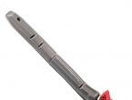
To connect to the controller from the servo, 3 wires are pulled, most often crimped with a standard 3-pin connector with a pitch of 2.54mm (1). Wire colors may vary. Brown or black - ground (minus), red - plus of the power source, orange or white - control signal. I will talk about control signals a little later.
So, the signal comes to the board, which will convert this signal into pulses sent directly to the engine (2). We will return to it a little later.
Finally, we have reached the detail, thanks to which we can read and set the angle of rotation of the servo (3). On the Internet, I found an excellent GIF showing the principle of the potentiometer.
The principle of operation of the potentiometer is simple. The potentiometer has 3 pins. Plus and minus power is supplied to the extreme terminals (polarity does not matter), there is a resistive substance between the terminals, along which the slider connected to the middle terminal moves. In our case, we will agree that on the far left we have a plus, on the far right we have a minus. By rotating the knob from the left extreme position to the extreme right position, we increase the resistance, and at the same time reduce the voltage from the input to the conditionally minimum, which we will remove from the middle output. The value of the minimum voltage will depend on the value of the maximum resistance of a particular potentiometer. In the servos we are considering, 5 kilo-ohm potentiometers are most often installed.
We figured out the device, now let's get back to the servo. The servo drive knob is docked with the servo output shaft, therefore, when the output shaft is turned, we change the value on the potentiometer. We conditionally accept the input voltage (potentiometer knob in the extreme right position) equal to five volts, let the potentiometer turn off all the voltage in the extreme left position and the minimum voltage will be zero, and at the midpoint then we will have two and a half volts. From these conditions, we get that at an angle of 180 ° at the output of the potentiometer we have 5 volts, at 90 ° 2.5 volts, and at 0 ° 0 volts. Why am I talking about this in such detail? We return again to the control board.
The servomotor is in position 0°. We apply a control signal to the input of the control board, which carries information about the rotation of the servo by 90 °. The electronic filling of the board reads the potentiometer readings, sees 0 volts on the potentiometer, and in the program it is clogged that it should be 2.5. That's the whole point. The board analyzes the difference, then selects the direction of rotation of the motor and will rotate it until the voltage at the output of the potentiometer becomes equal to two and a half volts.
Let's go further. In order not to flip the page up again, in search of a picture, I will give it again.
The micromotor (4) is not able to develop a powerful force on the shaft (torque), but it has a high rotation speed. To convert a high angular velocity with a small moment into a low one with a high one, which is exactly what we need, we should use a gearbox. The gearbox is represented by gears connecting the motor shaft and the output shaft (5). A gear with fewer teeth drives a gear with more. from this, the speed decreases but the moment increases. You can more clearly understand the principle of operation of the gearbox by picking up a servo drive and trying to turn the servo rocker. Difficult? Of course, because on the reverse side the gearbox turns into a multiplier, a mechanical device that, on the contrary, converts a low-speed powerful moment into a high-speed weak one.
The main characteristics of servos:
. Shaft force
The force on the shaft, also known as the moment, is one of the most important indicators of a servo drive and is measured in kg / cm. The specifications are usually indicated for two supply voltage options, most often for 4.8V and 6.0V.
A moment of 15 kg / cm means that the servo is able to keep a rocking chair stationary in a horizontal position with a shoulder of 1 cm and a load of 15 kg suspended from it, or to hold a load of 1 kg on a rocking chair with a shoulder of 15 cm.
The length of the rocking arm is inversely proportional to the mass of the load being held. For this drive, with a length of 2 cm, we get 7.5 kg, and by reducing the length of the lever to 0.5 cm we get as much as 30 kg
. turning speed
Turning speed is also one of the most important characteristics. It is customary to indicate it in the time equivalent required to change the position of the servo output shaft by 60 °. This characteristic is also most often indicated for 4.8V and 6.0V.
For example, a characteristic of 0.13sec/60° means that a turn of this servo by 60° can be completed in at least 0.13 seconds.
. Servo type
Digital or analog
. Supply voltage
Most hobby servos range from 4.8V to 7.2V
. Angle of rotation
This is the maximum angle that the output shaft can turn. Servo drives for rotation angles are mainly 180° and 360°.
. Servo constant rotation
Servo drives and constant rotation are produced. If it is not possible to purchase one, but it is very necessary, then you can remake a regular servo.
. Reducer type
Servo gearboxes are made of metal, carbon fiber, plastic or are assembled from metal and plastic gears.

Plastic gears poorly withstand loads and shocks, but they have very little wear. Carbon fiber is stronger than plastic, but much more expensive. Metal gears withstand heavy loads, shocks, falls, but this type of gear has the largest wear.
I would also like to note that the output shaft on various servos is installed differently. On most, the shaft slides on sleeves, on more powerful servos, ball bearings are already used.

Servo drives sizes:
Servo drives are divided into 4 main sizes. The following are the types of servos with their weights and dimensions. Dimensions of various servos may vary slightly from those shown below.
Micro: 24mm x 12mm x 24mm, weight: 8-10g.
Mini: 30mm x 15mm x 35mm, weight 23-25g.
Standard: 40mm x 20mm x 37mm, Weight: 50-80g.
Giant: 49x25x40mm, weight 50-90g.
A series of articles about servos:
Buy in Russia
In this lesson, we will consider the device and the principle of operation of servos. Let's analyze two simple sketches for controlling a servo using a potentiometer on Arduino. We will also learn new commands in the C++ programming language − servo.write, servo.read, servo.attach and learn how to connect a library in sketches to control servos and other devices through Arduino.
Servo motor device (servo)
A servo drive (servo motor) is an important element in the design of various robots and mechanisms. This is an accurate performer that has feedback that allows you to accurately control the movements of mechanisms. In other words, receiving the value of the control signal at the input, the servomotor seeks to maintain this value at the output of its actuator.
Servo drives are widely used to simulate the mechanical movements of robots. The servo drive consists of a sensor (speed, position, etc.), a drive control unit from a mechanical system and an electronic circuit. Reducers (gears) of the device are made of metal, carbon fiber or plastic. The plastic gears of the servomotor do not withstand heavy loads and shocks.
The servomotor has a built-in potentiometer which is connected to the output shaft. By turning the shaft, the servo changes the voltage value on the potentiometer. The board analyzes the voltage of the input signal and compares it with the voltage on the potentiometer, based on the difference, the motor will rotate until it equalizes the voltage at the output and the potentiometer.
 Servo control with pulse width modulation
 How to connect a servo to Arduino
The wiring diagram for a servo to Arduino is usually as follows: black wire to GND, red wire to 5V, orange/yellow wire to analog PWM (Pulse Width Modulation) pin. Servo control on Arduino is quite simple, but servomotors can be rotated 180 ° and 360 ° in rotation angles, which should be taken into account in robotics.
For the lesson we need the following details:
- Arduino Uno / Arduino Nano / Arduino Mega board;
- Bread board;
- USB cable;
- 1 servo;
- 1 potentiometer;
- Wires "father-father" and "father-mother".

In the first sketch, we'll look at how to control a servo on an Arduino using the myservo.write(0) command. We will also use the Servo.h standard library. Connect the servo to the Arduino board, according to the diagram in the photo above and upload the finished sketch. In the void loop() procedure, we will simply set the desired angle of rotation for the servo and the amount of time to wait until the next rotation.
Arduino servo sketch
#includeExplanations for the code:
- The Servo.h standard library contains a set of additional commands that can greatly simplify the sketch;
- The Servo variable is necessary so as not to get confused when connecting multiple servos to the Arduino. We give each drive its own name;
- The servo1.attach(10) command binds the drive to analog output 10.
- In the program, we rotate the drive 0-90-180 degrees and return to the initial position, since the void loop procedure is repeated cyclically.
Servo control by potentiometer
 Connecting a servo and potentiometer to Arduino Uno
 Arduino allows not only to control, but also to read indications from a servo. The myservo.read(0) command reads the current servo shaft angle and we can see it on the port monitor. Let's provide a more complex example of controlling a servo with a potentiometer on Arduino. Assemble the potentiometer circuit and upload the servo control sketch.
Sketch for a servo with a potentiometer
#includeExplanations for the code:
- This time we named the servo in the sketch as servo ;
- The servo.write(analogRead(A0)/4) command transfers the values for the servo shaft - we divide the received voltage from the potentiometer by four and send this value to the servo.
- The Serial.println (servo.read(10)) command reads the servo shaft angle value and sends it to the port monitor.
Servo motors are often used in various Arduino projects for various functions: turning structures, moving parts of mechanisms. Since the servo motor constantly strives to maintain a given angle of rotation, be prepared for increased power consumption. This will be especially sensitive in autonomous robots powered by batteries or batteries.
Also often read:

Modern high-tech equipment involves the use of structural elements that allow you to make constant dynamic movements with constant control of the angle of rotation of the shaft, as well as provide the ability to control speeds in electromechanical devices. The whole complex of such tasks can be solved with the help of servomotors. They are an electrical drive system that allows you to effectively control speeds in the required range. The use of such devices makes it possible to realize the periodic repetition of processes with a high frequency. Servo motors are an innovative version of the electric drive, so they are widely used in mechanical engineering and other industries. Such devices combine high efficiency in operation and low noise level.
Servo motor device
The design of the servomotor requires the following elements:
- rotor;
- stator;
- Components intended for switching (plugs or terminal boxes);
- Feedback sensor (encoder);
- Node of management, control and correction;
- On and off system;
- Cases (in case-type engines)
The main constructive difference between the devices under consideration and conventional DC and AC motors, equipped with brushes or without them, is the ability to control them by changing the rotor speed, torque and position.
The engine can be turned on and off using the system mechanical(resistors, potentiometers, etc.) or electronic(microprocessor) type. It is based on the principle of comparing the data of the feedback sensor and the set value with the voltage supplied through the relay to the device. More high-tech schemes also take into account the inertia of the rotor, which ensures its smooth acceleration and deceleration.
Conceptually, all servo motors can be classified as high-power actuating systems for precision positioning systems, machines, and devices. The main task of the servomotor is to position the actuator exactly at the desired point in space.
Principle of operation

The main aspect of the functioning of servomotors is the conditions of its operation within the system G codes, that is, control commands contained in a special program. Considering this issue with an example CNC, then the servomotors operate in conjunction with converters that change the voltage value at the armature or on the exciting winding of the motor, based on the input voltage level. Usually the whole system is controlled by the CNC rack. Upon receipt of a command from the rack to travel a certain distance along the X coordinate axis, a certain amount of voltage is generated in the rack's digital to analog converter subunit, which is transmitted to power the drive of the specified coordinate. In the servomotor, the rotation of the lead screw begins, with which the encoder and the executive body of the machine are connected. In the first, pulses are generated, counted by the rack. The program provides that a certain number of signals from the encoder corresponds to a certain distance of passage of the executing mechanism. When the required number of pulses is received, the analog converter outputs zero output voltage and the servomotor stops. In case of displacement under external influence of the working elements of the machine, a pulse is generated on the encoder, which is calculated by the rack, a mismatch voltage is applied to the drive, and the motor armature rotates until a zero mismatch value is obtained. The result is an accurate retention of the working element of the machine in a given position.
Varieties of servomotors
Like other devices, servomotors are available in several versions. These types of products are:
- Collector;
- Collectorless.
Devices can be powered by both direct and alternating current. AC servomotors are relatively cheap. The products are also available on the market in asynchronous and synchronous versions. In the synchronous version, during the operation of the product, the movement of the magnetic field coincides with the rotation of the rotor, so their direction relative to the stator is the same. Asynchronous devices are controlled by changing the parameters of the supply current (changing its frequency using an inverter). For servomotors that are driven by direct current, the abbreviation DC is provided. This type of product is most often used in equipment designed for continuous operation, since they are distinguished by greater stability during operation.
Specifications of servomotors
The performance characteristics of synchronous and asynchronous motors are slightly different.
| Synchronous servomotors | Asynchronous servomotors |
| They have high working dynamics (speed of transition from a static to a dynamic state). | They have medium and high dynamics in work. |
| During the period of large moments of inertial loads, they are moderately well regulated. | At peak moments of loads of inertial type, they are well tuned. |
| Able to withstand high overloads (up to 6 Mn, depending on the type of unit). | The ability to overload is approaching a threefold value. |
| They have a high limit of permissible thermal loads when operating for a long time in the entire range of the shaft speed. | Motors are able to withstand high thermal loads, the level of which depends on the speed of rotation of the shaft. |
| The product is cooled using convection technology, as well as using specially provided heat sinks or by thermal radiation. | The cooling of the parts of the mechanism is carried out using an impeller placed on the shaft, or by force. |
| High quality shaft speed control. | The shaft speed is regulated with a high level of quality. |
| Long-term operation with starting torque at low speeds is possible. | High thermal loads make long-term operation at low speeds impossible without forced cooling. |
| The converter (depending on the characteristics) allows you to control the speed in the range of 1 to 5000 or even more. | The speed is controlled by a converter with high efficiency in the range from 1 to 5000 and more. |
| At low speeds, torque ripples are observed. | During operation, there are practically no torque ripples. |
Application areas of servomotors
Due to their high dynamics, excellent positioning accuracy and overload resistance of servomotors, they are used in various fields of activity. Most of these products are used in the steel industry, in the manufacture of winders, extruders, plastic injection molding machines, printing and packaging equipment, in the food industry and in the beverage industry. Also, devices are an integral part of CNC machines, pressing and stamping equipment, car production lines, etc. main direction applications of servomotors are feed drives and positional machine digital control systems.
Connecting servos

When connecting a servomotor, first of all, make sure that the power cables are connected correctly. Servomotors have two sets of wires. Power (power) and wires from the encoder. There are 3 power wires in the bundle, they are connected to the driver. The wires from the encoder are connected to the COM port of the driver. The type of food and its value depends on the type of product.
Small servos usually have 3 wires. 1 wire is common, 1 is positive and 3 is a signal wire, from the speed sensor. Such a power supply scheme is common for low-speed, low-power servos that have a gearbox in their design.
It is recommended to use shielded twisted conductors for transmission of control signals. To exclude the possibility of interference of electromagnetic fields, it is not necessary to place the power cable and control wires side by side. They should be located at a distance of at least thirty centimeters.
Advantages and disadvantages of servomotors
Servo motors are quiet and smooth in operation. These are reliable and trouble-free products, due to which they are widely used in the creation of critical actuators. High speed and movement accuracy can also be achieved at low speeds. Such an engine can be selected by the user depending on the upcoming tasks to be solved. The disadvantages include the high cost of the module, as well as the complexity of its configuration. The production of servo motors requires high-tech industrial equipment.
In this way, users can purchase servo motors that are most suitable for the conditions of their future operation, creating an actuator that is highly reliable and functional.
Many people ask the question: servo - what is it? The classic servo design includes a motor, a position sensor and a three-loop control system (position, speed and current regulation).
The word "servo" is of Latin origin "servus", literally translated as "slave", "assistant", "servant".
In the engineering industry, devices acted as auxiliary components (feed drive in a machine tool, robot, etc.). However, today the situation has changed, and the main purpose of the servo lies in the implementation in the field of servo mechanisms.
The installation of a servo drive is justified in the case when conventional ones do not sufficiently regulate the accuracy of work.

The use of high quality instruments is necessary in equipment with a high level of performance.
This article will talk about the servo, what it is and how it functions.
Areas of use of the device
In the modern world, when automation has taken a strong position in all areas of mechanical engineering, the design of all mechanisms has noticeably unified. In this case, modern individual drives are used.
In order to understand what a servo is, you need to know the scope of the device.
The devices contain precision structures for maintaining speed in and machine tools with high accuracy. They are mounted on drilling equipment, in various transport systems and auxiliary mechanisms.
The devices are most widely used in the following areas:
- production of paper and packaging;
- production of metal sheets;
- material handling;
- production of transport equipment;
- production of building materials.
Servo for car trunk
There are many models of car trunk servos from different manufacturers. Consider the functionality of such a device as a trunk servo from the domestic manufacturer Avtozebra. The device is designed for Russian cars, but not only. For example, it can be used in a Renault Logan car.

According to user reviews, this design is convenient. It allows you to open and close the trunk without leaving the car.
The device is controlled by means of a button mounted in the passenger compartment or in
The reason for the widespread use of the device
The reason for the frequent use of servo drives was:
- the possibility of obtaining control, characterized by high accuracy and stable operation;
- wide range of speed control;
- high level of resistance to interference;
- small size and weight of the device.
The principle of operation of the servo
How does the device work? A servo, based on feedback from one or more system signals, regulates an object. The output indicator of the device enters the input, where it is compared with the setting action.
Movement Features
The servo drive device has two main features:
- the ability to increase power;
- providing feedback information.

Amplification is required for the purpose that the energy required at the output is very high (comes from an external source), and at the input its indicator is insignificant.
Feedback is nothing more than a closed circuit in which the signals are not matched at the input and output. This process is used for management.
The conclusion follows from this: the circuit in the forward direction serves as an energy transmitter, and in the reverse direction it serves as a transmitter of information that is needed for control accuracy.
Power supply and pinout of device connectors
A servo that is applicable to RC configurations typically has three wires:
- Signaling. A control pulse is transmitted through it. As a rule, the wire is colored white, yellow or red.
- Feeding. Its power indicator is from 4.8 to 6 V. Often, this is a red wire.
- Grounding. The wire is black or brown.

Actuator dimensions
Aggregates are divided into three categories:
- microdrives;
- standard modifications;
- large devices.
There are servos with other dimensions, but the above types make up 95% of all devices.
Main characteristics of the product
The operation of the servo is characterized by two main indicators: the speed of rotation and the force on the shaft. The first value serves as an indicator of time, which is measured in seconds. The force is measured in kg / cm, that is, what level of force the mechanism develops from the center of rotation.

In general, this parameter depends on the main purpose of the device, and only then on the number of gearbox gears and the nodes used in the device.
As already mentioned, mechanisms are now being produced that operate at a supply voltage of 4.8 to 6 V. More often this figure is 6 V. However, not all models are designed for a wide voltage range. Sometimes the servo motor only runs at 4.8V or only at 6V (the latter configurations are extremely rare).

Analog and digital modifications
A few years ago, all servo circuits were analog. Now there are also digital designs. What is the difference between their work? Let's turn to official information.
According to the Futaba report, over the past decade, servo drives have become more technically superior than before, as well as small size, high rotational speed and torsion elements.
The latest round of development is the emergence of a digital device. These units have significant advantages even over collector-type motors. Although there are some downsides.
Externally, analog and digital devices are indistinguishable. Differences are fixed only on device boards. Instead of a microcircuit on a digital unit, you can see a microprocessor that analyzes the receiver signal. He controls the engine.
It is completely wrong to say that the analog and digital modifications are fundamentally different in operation. They may have the same motors, mechanisms and potentiometers.
The main difference is the method of processing the incoming signal of the receiver and engine control. Both servos receive the same power signal from the radio receiver.
Thus, it becomes clear, servo, what is it?
The principle of operation of the analog modification
In the analog modification, the received signal is compared with the current position of the servomotor, and then the amplifier signal is sent to the motor, causing the motor to move to the specified position. The process frequency indicator is 50 times per second. This is the minimum response time. If you reject the handle on the transmitter, then short pulses will begin to flow to the servo, the interval between which will be equal to 20 m / s. Between pulses, nothing enters the motor, and external influences can change the functioning of the device in any direction. This time interval is called the "dead zone".
How the digital design works
Digital devices use a special processor that operates at high frequencies. It processes the receiver signal and sends control pulses to the motor at a rate of 300 times per second. Since the frequency indicator is much higher, the reaction is noticeably faster and holds the position better. This causes optimum centering and a high level of torsion. But this method requires a lot of energy, so the battery used in the analog movement will be discharged much faster in this design.
However, all users who have ever encountered a digital model at least once say that its difference from the analog design is so significant that they would never use the latter again.
Conclusion
Digital analogs will be your choice if you need:
- high level ;
- minimum number of "dead zones";
- precise positioning level;
- quick response to the command;
- constant force on the shaft when turning;
- high power level.
Now you know what a servo is and how to use it.