Homemade power bank for your phone. Homemade power bank? it's simple! The most common materials are
Often there is a need to charge your gadget at a time when there is no power supply nearby. In such a situation, Power Bank will come to the rescue. Such a battery can be purchased at any electronics store. But there is an interesting point - you can build it yourself. Let's talk about how to make a Power Bank with your own hands.
First assembly method
Let us immediately note that for assembly you do not need any expensive parts; you need batteries, a USB connector and ordinary materials that can be found in any home.
Let's try to make a battery using the first method:
- We take two matchboxes. We cut, bend one of the walls of each to the side, and then glue it together. When you get a single design, put two batteries in each box.
- Now we use the staples. They will be needed to create reliable contact between the boxes. They must be secured at the ends on both sides, and then connected with wire.

- The battery is almost ready. All that remains is to build the body. The ideal option would be a small box into which you can stick the resulting structure so that the gap is minimal.
- When the previous step is completed, take a plastic vitamin jar and make a small hole in it into which you insert the USB connector. Carefully secure it and solder the wire that connects to the battery. Now you should place this entire structure in a jar, which can be closed with a lid with a built-in USB connector.

Second way
An original method that allows you to construct a Power Bank from a regular flashlight. Here we will need a voltage converter that will help achieve the 5 volts required for charging.
To subsequently switch between the flashlight and the Power Bank, you need to disassemble it and remove the resistor attached to the LED; it activates the transition to a less bright light.
Where previously there was a plug required for recharging, a converter with a connector should be installed. The next step involves soldering the battery terminals to the charge controller. Then the converter should be soldered to its output contacts. Now we check the resulting design for functionality, if everything works out, you can fasten the components dangling in the body using epoxy glue.

Third method
You will need several old batteries from mobile devices and a charge controller. We wrap the batteries with tape and solder the side terminals in parallel. The central ones can be left alone, as they control the charge level indication. We solder the wires to the charge controller and place the entire structure in a suitable container, having previously made a hole in it for the USB connector.
We hope that now you will be able to make an external battery with your own hands.
Homemade power bank - it's very simple!
I suggest you read the description of my homemade product, perhaps it will give you the impetus to make something similar with your own hands.
At the moment, a huge number of power banks of different configurations, sizes and with various additional options are available for purchase.
But I decided to assemble it myself. The reasons that prompted me were quite compelling: reluctance to spend money on a purchase (with a possible lottery), the presence of both charging boards and step-up converters up to 5 Volts. And also the presence of a huge number of batteries lying idle. The situation was aggravated by a friend who brought a dozen 18650 from a laptop.
The photo shows only a small part of the batteries. 
I bought cheap power banks for 1 element 18650 in online stores 
and bought the 18650 elements themselves, but apparently the experience was unsuccessful, or tension with money gave rise to creativity.
Power banks for 1 cell with a capacity of up to 2600 mAh (classic case) did not allow us to fully charge a smartphone, not to mention a tablet. In addition, the batteries purchased on the Internet turned out to be fake with a real capacity of 1000 mAh. 
I bought 4 pieces, but I decided to open one to make sure it was a fake, but I accidentally shorted the poles and my battery caught fire. Fortunately, I was poking around on the balcony and, without hesitation, threw it from the 5th floor onto the street. It was winter, the temperature melted the battery from the snow and ice, and no matter how much I tried to look for it later, I never found it. That's why I found it in the spring. There are no photos, but it was a pitiful sight. What I mean is that lithium batteries require more careful handling.
I thought about the configuration of the power bank:
Frame
Initially I planned to assemble the batteries in a “pipe”, I saw something like this in a girl’s queue at the post office, but for 2-3 elements it turned out to be some kind of tube with large dimensions, which cannot be put in a pocket. It was decided to place the elements side by side (classic option). Another question arose - what should the body be made of? There was an idea to make it out of fiberglass with epoxy resin and had already started working on it, until at work with electricians I saw a plastic pipe for laying electrical wiring. 

The manufacturing process is as follows: we take 2 batteries (3-5 as many as you need), a plastic pipe and a hairdryer (construction), you can try softening the pipe in boiling water, I have not tried this option.
We wrap the batteries with several layers of electrical tape or tape. We heat the plastic pipe evenly with a hairdryer and insert the batteries. Next, the pipe cools while maintaining its shape. All that remains is to push out the batteries and part of the case is ready. Next, we remove the electrical tape (adhesive tape) from the elements so that they can be inserted freely (but without looseness) into the new body. By the way, I didn’t succeed the first time, I stopped on the second attempt, but the body turned out to be a little like a propeller (I eliminated the distortion by sanding both sides).
Cut to length and sand the end with sandpaper or a file.
Next, take a piece of plexiglass, moisten it with dichloroethane (carefully poisonous) and glue it to the pipe. 
After 10 hours (dry outside or under ventilation), grind it using sandpaper or any available method. We get a glass with a bottom.
Scheme 
It can be said that there is practically none - 2 wires from the charging board to the battery, 2 wires from the boost converter board to the charging board, which, when the battery discharges to the lower level, will turn off the power to the boost converter. If you bought a boost converter board with a soldered USB connector, this simplifies the design. On a USB connector, you can connect the two middle pins to each other. Some phones use a jumper to recognize that they are connected not to a computer port but to a charger and begin to charge with a higher current (1000 mA instead of 500). I had to solder the connector to the back of the charging board. The main nuance is to observe the polarity and try to use red wires for + (any light) and blue (any dark) for minus. Subsequently, developing the habit of using different colors simplifies life. 
There are many options, but they all come down to the use of the same microcircuits as well as field-effect transistors as a battery cut-off element during discharge. Oh yes, I used the batteries without protection.
Here you will need a soldering iron to connect the boards to each other and the batteries, as well as pieces of small-section wires (the length is short, not critical).

To suit your taste and color, any one that increases up to 5 Volts and produces a current of at least 1 Ampere.
The board I use does not have protection against short circuits at the output, but I use the device for its intended purpose, so there is practically no chance of burning the converter.
A small drawback - the converter consumes 500 μA (0.5 mA) without load, but it will take 8000 hours to discharge the batteries. Can be neglected.
There was also a need for a soldering iron. I packed the soldered board into a piece and made a hole for an LED - an indicator of the converter's operation. This was necessary for the reason that the boards in the case were not fixed in anything and it was necessary to avoid short circuits.


I recommend using used laptop batteries, cheap and cheerful.
My next power bank will be on batteries from a dead tablet.
We fix the elements together and coat them with automotive sealant, then we connect the contacts + to + and - to -, that is, in parallel.
There is a SERIOUS POINT here! Before connecting, it is necessary to bring the EMF of the elements to the same value. Let opponents write that all this is nonsense and the machinations of enemies, but from my own experience I was convinced of the need for balancing. For balancing, I prepared a 3.5 Volt flashlight bulb, but I was distracted at work and successfully forgot about balancing. I soldered both ends of the elements (soldering is performed in the presence of active flux or soldering acid; simply tinning with rosin will be problematic). You cannot warm up the soldering area for a long time - the battery may fail. The job is done, I'm waiting for the battery assembly to cool down, but it didn't work out that way, the structure started to burn my hand from heating, at first I thought that I had warmed it up so much with the soldering iron or damaged it, but it dawned on me - I didn't do the balancing. I quickly unsoldered it and connected + to + through the light bulb. After about 3-4 hours, I checked the current between the elements, it was no more than 5 mA, which means that the batteries have the same EMF and are ready for soldering.
additional little things(USB)
To complete the design, I lacked a USB port - I took it from some dead motherboard. I desoldered it in a vandal way - using a construction hair dryer.
There was an idea to use 2 USB ports and 2 converter boards at once (separate channels as expected), but there simply wasn’t enough space inside the case. and subsequently the presence of a 2nd USB port was not in great demand.
Everything is fixed inside with sealant (if you like a glue gun, you can use one too) The lid is glued and made in the same way as the bottom. 


I did not paint the power bank, the original gray color of the body seems acceptable, nothing prevents it from being sanded and spray painted.
After making the power bank, I thought that I shouldn’t have rushed. It was possible to use a kit from a cheap power bank and not reinvent the wheel, but then protected batteries would be required.
options to gut the cheap one, use different batteries
Some nuances in the process of making a power bank:
housing design - use of dichloroethane - poison 
It is difficult to remove shavings from plexiglass - they stick (static), it is highly advisable to select batteries from existing elements. I used the Imax B6 charger 
2 charge-discharge cycles with a current of 1 Ampere showed xy from xy! There were a decent number of cells with a capacity of less than 800 mAh, they went for recycling (they collect them at work and hand them over). Soldering should be done in the presence of ventilation. The batteries can be soldered with a powerful soldering iron; the boards can be soldered with a low-power one.
Tests
I recently had a trip to the city of Volgograd for the Russian F3K radio-controlled glider championship. This is where the power bank comes in handy. 32 hours on a train doesn’t seem like much, but with nothing else to do, we watched movies and played games on our smartphones and tablets. And if on the first day the sockets in the carriage were not available, then on the second day there was a queue of several hours waiting for anyone who wanted to recharge =) 
I put the power bank on charge at night when everyone was asleep, so I didn’t disturb anyone and was happy. The capacity of the power bank was enough to watch a movie and then charge the tablet at least three-quarters. 
At the hotel I left it to charge at night, during the day I used it myself and gave it to others. A completely discharged power bank charges in about 5 hours. The capacity turned out to be about 4100 mAh. The discharge current, depending on the cable, reaches 1 Ampere. When charging, the indicator lights up red, when charging is complete it turns blue. Like most 18650 charge controller boards.
When discharged, the red indicator lights up, but it is practically invisible, I did not think through the design thoroughly. 


Where would Kote be without her?

Conclusion: there are power banks with reasonable prices and better characteristics, but the presence of a 18650 mount and the desire to put your hands to it did the trick. a homemade product was born. Beta version with its shortcomings. My requests are completely covered, sometimes my daughter takes her to school.
The review was difficult, but interesting. Please point out any shortcomings. We will punish the guilty. We will encourage the rest. Missed points will be clarified and doubts will be dispelled =) I'm planning to buy +51 Add to favorites I liked the review +91 +189
A power bank can be not only a useful device that allows you to urgently charge a mobile gadget, but also a beautiful accessory. This material provides an overview of a video on making an original Power bank in an apocalyptic style.
We will need:
- USB charger for car;
- 9 volt crown battery;
- battery holder;
- switch;
- a can of deodorant;
- plastic;
- aerosol paint;
- acrylic paints

The first step is to open the device and disassemble it, removing the case and leaving only the circuit.

Now let's move on to making the box. To do this, you need to attach all the components of the charger along with the battery holder to the can, measure approximately how much space is needed inside and saw off the excess part of the can.

We also saw off the lower part, finishing everything with a file.

Cut a circle along the diameter of the can to close the can. You will also need another circle for the cover, which will allow you to replace the battery.


At this stage, you need to solder the battery holder and switch to the charger board, and also bring the LED light bulb out. Note that the positive contact is located near the spring of the charger, and the negative contact is located near a small iron part.


We check the charger for functionality.

We will attach the circuit to a round piece of plastic. To do this, mark the places that need to be cut, that is, the places for the USB connector and switch, as well as the hole for the LED.

We secure all parts with a glue gun. The long board from the charger can be additionally secured with small pieces of plastic.
Glue the round part to the can, placing all the components inside.

We carefully handle all the irregularities and additionally secure them with cold welding.
We glue a second circle to the lid of the can, which you can decorate at your own discretion.

If desired, you can make beautiful contours by cold welding, adding originality to the Power bank.

We also decorate the can with copper wires running along it.


Next, paint the can with green spray paint.


Now you can give the workpiece a slightly rusty appearance. This can be done using acrylic paints.

It is also necessary to make small splashes on the sides to make the rust look more realistic. You can do this with an old toothbrush.
Sometimes, there are situations when you need to charge your phone or camera, but there is no outlet nearby. In this case, a device called a “power bank” will come to the rescue.
Such a device usually consists of a pair or three small batteries, a charger for them and a voltage converter for the device being charged, be it a flashlight, a mobile phone or a camera.
I took the batteries from an old laptop battery, size 18650, to charge them I decided to use the Chinese TP4056 microcircuit, specially designed for charging Li-Ion batteries, and bought a boost converter built on the CE8301 microcircuit in the form of a ready-made module. Microcircuits and modules, ordered on eBay.com.
TP4056 has a number of positive features, namely:
1. Protect batteries from overcharging and overheating
2. A small number of external elements
3. Indication of operating modes
4.Adjustable charge current
5. Low cost
6. Etc. and so on.
TP4056 connection diagram

The charge current is adjusted by resistor Rprog. I set it to 2.2 kOhm, charging current 500mA.

CE8301 has a million similar analogues, there’s no point in focusing too much on it, I’ll just say that it operates from 0.9V to 5V, while the output holds 5V 500mA (600mA maximum), which is quite enough to charge most mobile phones and cameras.
Wiring diagram CE8301

Photos of converters

I wanted to make the finished device quite functional, so I decided to use 2 converters if I had to charge a couple of devices at once, and for batteries I decided to take as many as 4 TP4056 chips so that I could use batteries with different capacities.
To ensure that the TP4056 microcircuits do not influence each other, the batteries are connected through Schottky diodes, with a drop of 0.2 Volts.
The final diagram looked like this


Made

Checked

And installed all the components


The black droplets with the inscription 103 are 10 kOhm thermistors.
The board turned out to be quite compact, taking into account the fact that only 10 µF capacitors and TP4056 microcircuits were used from SMD components. When soldering, I placed pieces of masking (paper) tape under the housing of the microcircuits so that the heat sink of the microcircuits did not short out the tracks.
The circuit works great, nothing gets hot. During charging, the red LED lights up, when the battery voltage reaches 4.2V, the red LED goes out and the green LED lights up - charging stops. If the thermal protection has tripped, the LEDs do not light up, and if there is no battery connected to the circuit, the green light is on and the red flashes. Charging of cans of the same capacity and with the same residual voltage occurs quite synchronously. In general, I got exactly what I wanted.
Most modern multifunctional gadgets have one annoying drawback - they quickly run out of charge, especially when multitasking. Therefore, many smartphone owners have already acquired a “magic wand” in the form of recharging away from power sources. We will tell you in detail how to build such a power bank with your own hands.
What is Power bank
A power bank is a portable battery with a capacity of 2 to 15 thousand mAh. The higher this indicator, the longer the device will be able to power your gadget. It is easy to use by connecting the power bank and phone, tablet with a USB cable. It’s quite easy to make such a power bank with your own hands from scrap materials.
These devices come in the following varieties:
- Lithium-ion - lightweight, with no charge memory, high energy density, low self-charge k.
- Lithium-polymer - surpasses the first type in terms of energy density per unit volume and weight.
- Equipped with a solar battery - the charging power depends on its area.
Some models are equipped with two or even several USB outputs for recharging several gadgets at the same time, an LED (light) indication or LCD display for displaying service information about the level and charging process, as well as an LED flashlight.
Power bank made from old phone batteries
In order to make such a device, you will need from six to nine unnecessary but working batteries from phones (it is advisable to select their capacity from 1200 mAh). A do-it-yourself power bank from telephone batteries is made using this simple algorithm:
- Carefully wrap three batteries at a time with tape - you will have two or three stacks. Make sure that the terminals of all batteries face the same direction and are not covered with adhesive tape.
- Choose a suitable case for the device - a plastic box, a soap dish.
- Soldering together the outer terminals of all batteries - “plus” with “plus”, “minus” with minus.” The middle terminal is a temperature sensor that allows you to find out the remaining capacity level. You don’t have to touch it.
- Inside the case, draw a controller location on the edge and make a hole for the USB connector.
- Connect the batteries to the controller, then attach all the elements to the body with hot glue.
- Close the case with a lid or glue the halves of the soap dish together - the power bank is ready! The device is enough for 4-5 recharges of a medium-power gadget.
DIY power bank from car charger
To create such a mechanism you will need:
- eight 18650 lithium-ion AA batteries (3.6 V, 2200 mAh);
- car charger for mobile phone;
- housing from the car relay box;
- USB connector.

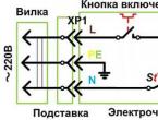
This do-it-yourself power bank (the diagram for connecting the elements is presented above) is made according to the following instructions:
- Mark and drill holes in the housing from the block for the USB output and the future switch.
- According to the attached diagram, solder the batteries together into two blocks of 4 pieces.
- Place the elements in the case, attach them with hot glue for reliability.
- Solder the batteries to the on/off block.
- Then connect the switch to the USB connector, based on the symbols in the diagram.
The power bank can fully charge your phone battery once or twice when using the cable. To start the charging cycle, flip the switch to the “on” position; when finished, do not forget to turn off the Power bank.
Power bank made from AA batteries
Necessary materials:
- several wires;
- USB connector;
- a box in which photographic films are sold;
- a small plastic bottle (for medicines, vitamins);
- staples;
- a can of deodorant or air freshener;
- wire;
- 2 matchboxes;
- 4 AA batteries.

How to make a power bank with your own hands:
- Bend over the top wall of each matchbox, glue them together with their bases, and place two batteries inside each.
- Using staples, create contact between the batteries from two boxes and secure them with wire.
- Fold the device compactly into a film box.
- Make a hole in the bottom of the plastic jar for the USB output. Secure it inside the can, solder wires to it.
- Connect the USB connector to the batteries.
- Cut off the top of the can and secure the structure inside with hot glue. The lid will be the bottom of the jar with a USB output.
Power bank from a screwdriver battery
This DIY power bank is made from:
- a suitable housing for the future device;
- phone charger;
- switch buttons;
- voltmeter;
- USB connector;
- screwdriver battery (Li-ion 2000 mAh, 10 pieces of 1865 batteries).

The idea is implemented like this:
- Secure three blocks of three batteries with electrical tape.
- Three are connected to each other in series, three in parallel.
- Make holes in the case for the toggle switch and for the USB connector. Secure these elements inside.
- The switch button here performs two tasks: one position is charging the device itself, the second is charging the smartphone.
- Connect a voltmeter. Its function is to display the input current during charging and display information about the charge level of the device.
Power bank from a flashlight
To convert a flashlight into a Power bank you will need:
- the flashlight itself with a 3.7 volt battery;
- controller;
- voltage converter with USB output (so that 3.7 volts goes to the required 5).

DIY power bank:
- Remove the flashlight resistor to which the LED is attached - to change the "bright light" mode to a power bank.
- Remove the plug that was used to charge the flashlight, replace it with a USB output with a current converter.
- Solder the "+" and "-" flashlight batteries to the controller.
- Find the “OUT+” and “OUT-” pins on the controller. A 5-volt converter must be connected to them.
- Before operating the switch, release one of its contacts. Then solder the converter directly to it.
- Perform a functional check of the converter. If the result is unsatisfactory at this stage, you can resolder the contacts.
- If the test is successful, use epoxy glue to carefully attach both the controller and the converter to the body of the former flashlight.
- Assemble the structure - you now have a power bank of an unusual shape.
Purchasing a power bank sometimes becomes necessary when purchasing a gadget, especially with a large screen that “eats up” the lion’s share of the charge. However, if you have a minimum level of skills, it is quite possible to assemble this useful device yourself. We hope our advice helped you with the latter.