DIY digital UHF antenna. The antenna is decimeter. Antennas for television. UHF indoor antenna. Do-it-yourself decimeter antenna. Electromagnetic wave bands
The main indicator of the quality of each antenna is its interaction with the air signal. This principle of operation underlies both purchased and homemade antennas. We suggest that you familiarize yourself with recommendations on how to make an antenna for digital TV with your own hands.
Features of modern television
If you compare modern television broadcasts with the broadcasts that existed several years ago, you can find certain differences. First of all, the UHF range is used for television broadcasting. Thus, it is possible to significantly save money and signal reception by the antenna. In addition, in this case, there is also no need for periodic maintenance of antennas.

Also, there are many more television sensors than before, so most television channels are available in almost all places in the country. To ensure television broadcasting in habitable areas, low-power sensors are used.
In big cities, radio waves travel differently. Due to the large number of multi-story buildings, the signal through them is weak. In addition, there are a huge number of television channels, for which one standard television antenna is not enough to receive.
With the development of digital broadcasting, receiving channels has become even easier. These types of antennas are distinguished by their resistance to interference, phase or cable distortion, and image clarity.
Simple DIY digital antenna: device requirements
Since television broadcasting conditions have changed, the rules for operating modern antennas have also changed:
1. One of the main parameters of a television antenna, in the form of directional coefficient and protection coefficient, are not particularly important. To combat various types of interference, various electronic means are used.
2. The coefficient responsible for the antenna gain improves the signal, clears it of extraneous sounds and various types of interference.
3. Another important quality of a modern television antenna is range. Electrical parameters are saved automatically, without additional human intervention.
4. The operating range of the television antenna should interact well with the cable that connects to the antenna.
5. To avoid the appearance of phase distortions, it is necessary to ensure decent antenna characteristics in the amplitude-frequency ratio.
The characteristics of the last three points are determined by the properties of receiving a television signal using an antenna. An antenna operating at one frequency is capable of receiving several wave channels. However, in order for them to be consistent with the feeder, it is necessary to have a USS that strongly absorbs signals.
Therefore, there are certain options for digital antennas available for making at home. We suggest you familiarize yourself with them:
1. All-wave version of the antenna, such devices are frequency independent, they are cheap, and very popular among consumers. One hour is enough to make such an antenna. Such an antenna is perfect for city apartments, but in a populated area that is somewhat distant from television centers, such an antenna will work worse.
2. Speech therapy band version of the antenna - such an antenna picks up certain signals. It has a simple design, is well suited for various operating ranges, and does not change the feeder parameters. It has average technical parameters and is excellent for country houses, dachas, and apartments.

3. Z-shaped antenna, which is also called a zigzag antenna. Making such a structure will require a lot of time and physical effort. It has wide receiving characteristics. With the help of such an antenna it is possible to expand the reception range of television channels.
To achieve precise matching between antennas, it is necessary to lay the cable across the zero potential value.
DIY digital TV antenna: reception characteristics
Vibraton antennas are capable of finding several more digital ones on one analog cantal. Such devices receive wave channels. They are rarely used and are relevant for places remote from television towers.
Making your own satellite dish is a pointless process. Since in this process you will need to purchase a commercial tuner and head, and the alignment of the mirrors must be very accurate, it is almost impossible to achieve it at home. You can only configure such an antenna yourself, but not manufacture it.
In order to make the above antenna options, you need to have a very good understanding of higher mathematics and electrodynamic processes. Among the main characteristics of the terms used in the manufacturing process of television antennas, we note:
1. KU - antenna power, which is determined in the ratio of the received antenna signal to its main lobe.
2. KND - the relationship between the solid circle and the solid angle of the antenna lobes. If there are lobes of different sizes, they change in area.
3. KZD - the ratio between the signal received at the main lobe and the total amount of antenna power.
Please note that if the antenna is a band antenna, then the power is taken into account in relation to the useful signal.
Note that the first two terms are not necessarily interdependent. There are certain antenna options that have high directivity, but unity or less gain. However, a zigzag antenna combines significant gain with a low directivity level.

DIY digital TV antenna: manufacturing technology
Each of the antenna elements, through which the current flows, supplying the useful signal, must be connected to the other by soldering or welding. Any prefabricated unit located outdoors must be well fixed, since the destruction of electronic contact on the street occurs faster than indoors.
Particular attention should be paid to zero potential. It is in these places that voltage nodes and electric current are located at its highest power. Solid bent metal is used to make zero-potential locations.
The braid or core is made from coaxial cable made from copper or an inexpensive alloy with anti-corrosion properties. To solder the cable, a forty-volt soldering machine is used, with low-melting solders and flux paste.
A do-it-yourself outdoor digital antenna is made in such a way that all connections are resistant to moisture, temperature changes and other environmental influences.

To make an all-wave antenna you will need two triangular plates, two slats made of wood and enameled wire. At the same time, the size of the wire in diameter is practically unimportant, and the interval between their ends is about 2-3 cm. The interval between the plates on which the ends of the wire are located is 1 cm. One-sided square-shaped fiberglass coated with foil can replace two metal plates. At the same time, copper triangles should be cut out on it.
The antenna's width should be the same as its height. The canvases open at right angles. In order to lay the cable to this antenna, you must follow a certain diagram. The cable braid is not soldered to the point indicating zero potential. She just gets attached to her.
The CHNA, which stretches 150 cm inside the window, is capable of receiving most meter and DCM channels of any direction. The advantage of this antenna is that it has a wide channel reception interval. Therefore, such antennas are popular in large cities where there are various television centers. However, such an antenna has certain disadvantages - the antenna gain is single, and the gain is zero. Therefore, in the presence of large interference, the antenna will be irrelevant.
It is possible to make other types of digital antennas with your own hands using CNA, for example, a logarithmic spiral of two turns. This version of the antenna is compact and easier to manufacture.
Over-the-air digital antennas made from beer cans
To make a digital antenna with your own hands from a cable, you will need beer cans. This version of the antenna, with the right approach to its manufacture, has good performance characteristics. In addition, such an antenna is quite simple to manufacture.
The operating principle of such an antenna is based on increasing the diameter of the arms on a conventional linear vibrator. In this case, the working band expands, while other properties do not change.
Beer cans, in proportion to their size, are used as arms on the vibrator. At the same time, the expansion of the shoulders is unlimited. This version of a simple vibrator is used as an indoor digital antenna with your own hands to receive television broadcasts by connecting directly via cable.
If you choose the option of assembling a common-mode grating from a beer diopole, located vertically, with a step of half a wave, you will be able to improve the gain value of the antenna. Also, this device must have an antenna amplifier installed, with the help of which the device is coordinated and configured.
To strengthen such an antenna, a CPD is added to it, a screen and a grid are installed on the back of it, with an interval of half a grid. To install a beer antenna, you will need a dielectric mast, while the screen and the mast are connected by a mechanical connection.
At the same time, about three or four rows are arranged on the grid. Two gratings are not capable of achieving high gain.
DIY UHF antenna for digital television
A log-periodic version of the antenna is called a prefabricated antenna, which is connected to the halves on a linear diopole, the interval between them varies in relation to the geometric parameters of the progression. There are configured and free lines. We suggest choosing a longer and smoother version of the antenna.
To manufacture LPA, it is necessary to have any predetermined range. The higher the progression indicators, the greater the gain of the antenna. In terms of operational and technical characteristics, this antenna option is ideal for manufacturing at home.
The main principle of its normal functioning is making correct calculations. With increasing progressive indicators, the gain increases and the directivity angle decreases. This antenna does not require an additional screen. Since it does not depend on its general characteristics.

When calculating a digital LP antenna, use the following recommendations:
- the second longest vibrator must have a reserve of frequency power;
- Next, the longest diopole is calculated;
- After this, another specified frequency range is added.
If the shortest diopole leaves lines, then it is cut off, since it is needed on the antenna only for calculations. The total length of the antenna will be about 40 cm.
The diameter of the lines on the antenna is about 7-16 mm. In this case, the interval between the axes is 40 mm. The cable is not tied to the line externally, as this will negatively affect the technical properties of the antenna.
The outdoor antenna is fixed to the mast using the center of gravity. Otherwise, the antenna will constantly shake under the influence of the wind. However, the metal mast is not connected to the line in a straight line, since a dielectric mast must be provided in this place, the length of which is about 150 cm. A wooden beam, previously painted or varnished, can be used as a dielectric material.
DIY digital antenna video:
Practical Amateur Radio Antenna Designs
Coaxial cable is used to transmit radio frequency electrical signals. It is used by radio amateurs to power antennas, but the antennas themselves can be built from this cable. So even small pieces, from 2 to 5 meters long, will go into use; by the way, they can be bought inexpensively at various kinds of "dealing sites", and in the amateur radio industry such scraps will be unclaimed, because they are too short to power antennas, and if twisted and then try to use them as a “solid” cable, then at least it will be completely impractical.
Coaxial cable, compared to copper wire of the same thickness, which is also widely used by radio amateurs in antenna construction, has advantages. The cable will be cheaper in price than copper wire, it is lighter, and, which is of course very important, it has sufficient mechanical strength for building antennas.
The shielding braid of the cable can be soldered with a low-power soldering iron (for antenna, often street work, this is important), and the outer sheath of the coaxial cable ensures its long-term operation under atmospheric conditions, since it was specially designed for this.
DIPOLE COAXIAL ANTENNA
The antenna shown in Figure 1 is a symmetrical antenna, regardless of its suspension - vertical or horizontal. The optimal option for powering such an antenna would be to power it through a balun, which can be made from the same coaxial cable as the antenna itself.
The simplest antenna made from coaxial cable is a regular vertical or horizontal dipole (Fig. 1).
A coaxial cable with a characteristic impedance of 50 or 75 Ohms is suitable to power this antenna.
In table 1 shows the lengths of the dipole arms for ranges from 2 to 20 meters.
Due to the relatively large thickness, the antenna has a fairly large broadband in these ranges.
Therefore, with strict adherence to the dimensions indicated in the table. 1. The antenna does not require adjustment.
The design of a simple balun is shown in Figure 2, and Table 2 shows data on its lengths for operation in ranges from 2 to 20 meters.
The lengths of the balun cable sections are indicated for a coaxial cable with polyethylene filling and a shortening factor of 0.66. Such a balun is also suitable for powering dipole antennas made from ordinary wire.
RESONATOR DIPOLE ANTENNA
A more efficient resonator antenna from coaxial cable can be built according to Figure 3. This antenna is a variant of an ordinary loop dipole made from coaxial cable.
The first mentions of such an antenna appeared in the literature back in the 50s; obviously, the invention of this antenna can be attributed to that time. As with many other antennas, it is not possible to accurately indicate the name of its inventor; obviously, with the spread of coaxial cable, such an antenna was invented almost simultaneously and independently in different countries.
A resonator antenna is sometimes used as part of some complex microwave antennas. This dipole antenna works like a regular classic loop dipole. The length of the arms of antenna "C" is a quarter of the wavelength. The length of the arms of antenna "A" is a quarter of the wavelength in the coaxial cable. Sections "B", made from shorted sections of coaxial cable, extend the arms of antenna "A" to a quarter-wavelength. The "B" pieces can be made from lengths of copper wire.
The antenna bandwidth is limited on one side by the bandwidth of the dipole formed by part “C”, and on the other side by the bandwidth of the quarter-wave resonator “A”. However, the resonator dipole has operability in the amateur VHF and HF frequency bands. Theoretically, the input impedance of a resonator dipole is equal to the characteristic impedance of the coaxial cable from which it is made. This allows you to use the same coaxial cable to power it as the one from which the antenna is made, which further increases its versatility.
The resonator antenna is symmetrical, and to power it it is advisable to use a balun shown in Figure 2. The dimensions of the resonator dipole antenna for operation in the ranges from 2 to 20 meters are given in Table 3.
UNSYMMETRICAL VERTICAL ANTENNAS FROM COAXIAL CABLE
An asymmetrical vertical antenna differs from a symmetrical one in that one of its arms or parts is made in a different way from the other part, or in that one of its parts will be influenced by foreign objects much more than the other.
The simplest design of an asymmetrical antenna made of coaxial cable is shown in Fig. 4. Here, the vertical part of the antenna can be suspended vertically using a nylon rope between two supports - trees, masts of other antennas (Fig. 4A), or suspended obliquely using a nylon cord from one of the supports (Fig. 4B). The counterweight of a whip antenna, made of coaxial cable, may be located in close proximity to the ground. For a vertical antenna, it is advisable to perform the counterweight as shown in Figure 5.
In this case, it is made of a quarter-wave insulator-resonator “A”, which is extended to the resonant frequency required for the operation of the counterweight by segment “B”. Section “B” can be made from either coaxial cable or copper wire. The lengths of parts “A” and “B” are given in table. 4. Table taking into account the use of coaxial cable with a shortening factor of 0.66.
A vertical antenna made of coaxial cable, with a quarter-wave resonator in a counterweight, has advantages over a vertical antenna with conventional counterweights. The canvas of the entire antenna is electrically closed, which makes its operation safe during a thunderstorm; the quarter-wave resonator has low resistance for non-resonant frequencies, and this provides additional frequency selection during reception and filtering of harmonics in the antenna system during transmission.
A vertical antenna made of coaxial cable, with one counterweight located at an angle of 90° to the pin, has a resistance close to 40 Ohms; a cable with a characteristic impedance of 50 Ohms is suitable for the manufacture and power supply of this antenna.
If you are using 75 ohm coaxial cable to power the antenna, you can match the antenna using a shortening capacitor.
SIMPLE ASymmetrical ANTENNA
A very simple monopole antenna can be made from coaxial cable. It was first described in amateur radio literature by W6SA1 in 1956. This antenna is called the "Slim cobra" antenna. Its various modifications appear from time to time in amateur radio literature.
This is a purely amateur radio antenna, since when reviewing quite a few sources, I did not come across any mention of its use in professional communications.
In Fig. Figure 7 shows the classic W6SA1 antenna. It is made entirely of coaxial cable, with a screen removed along the cable length of 0.24 wavelengths. This is the radiating part of the antenna. At a distance of 0.27 wavelengths from the radiating part, a high-frequency choke of 5-7 ferrite rings is made on the screen. The rings can be secured to the cable using insulating tape. The permeability of ferrite rings is not critical. This choke can ensure operation of the antenna with powers supplied to it of 100 - 200 W. Greater power level on the lower KB bands, and less power on the upper ones. If the specified power is exceeded, the ferrite rings may overheat and crumble.
If you still intend to operate at high powers, it is advisable to make the choke frameless, winding 10-20 turns of the same coaxial cable on a mandrel with a diameter of 30-60 mm. But, of course, such a choke is more bulky than one based on ferrite rings.
In a single-wire cable antenna, the length of the radiating part, taking into account the shortening factor, is equal to the length of the radiating part of a classic vertical antenna; the length of the “ground” of a single-wire cable antenna is slightly longer than the length of the classic counterweight.
This is due to the fact that when ground currents flow, there is no shortening coefficient, which occurs in dipole and asymmetrical vertical antennas.
In practice, it has been experimentally determined that the minimum SWR of an antenna made from a 50-ohm cable will be when the choke is located at a distance of 0.27 wavelengths.
The antenna can work in the field, it can be easily installed as an auxiliary antenna by simply “throwing” it from an upper floor window onto a tree or another house, and the antenna does not need to be adjusted.
Table 5 shows the antenna sizes for operation in the ranges from 2 to 40 meters.
COAXIAL VERTICAL ANTENNAS
The main advantage of coaxial-type antennas is the extended frequency band formed by a vertically located coaxial cable with an arbitrary characteristic impedance. The lower end of the central core of the cable is connected to the grounding system, and the upper end of the central core is soldered to the cable braid.
Coaxial vertical antenna circuit
(Rv - sum of loss resistances)
The length of the cable (emitter) is calculated at the rate of 1/4λ multiplied by the value of the cable shortening factor (usually this indicator is 0.66).
Thus, a coaxial closed quarter-wave line is obtained, acting as a parallel resonant circuit. Radio waves are emitted only by the cable screen, but due to the small l/d ratio its shortening factor is close to 0.95, and therefore it is too short for quarter-wave resonance.
To obtain a quarter-wave Groundplane, it is necessary to increase the length L1 with a segment L2 to a resonant length of 1/4λ.
For example:
A coaxial cable with a shortening factor Vk = 0.66 is used. Geometric quarter wavelength L1=0.25λ x 0.66 = 0.165λ.
If we take the shortening coefficient V = 0.95 for the cable shield, taking into account its l/d ratio, then the normal length will be L1 + L2 = 0.25λ x 0.95 = 0.2376λ, and the length of the segment L2 = 0.2376λ - 0.165 λ = 0.0725λ.
At resonance, the built-in quarter-wave loop does not work due to the very high input impedance (parallel resonant circuit). If you increase the transmitter frequency, the segment L1 + L2 will be too long - in other words, an inductive reactive component will appear on it. At the same time, the short-circuited quarter-wave coaxial line (loop) will become excessively long. A line exceeding a quarter wavelength has a capacitive effect, and as a result, the inductive component of the emitter segment and the capacitive reactivity of the quarter-wave loop are mutually compensated, and the radiation resistance increases.
As the transmitter frequency decreases, the opposite happens: the emitter segment becomes capacitive, and the loop becomes inductive, which also leads to mutual compensation of the reactive components.
Thanks to this ability of the quarter-wave line, the frequency band of the antenna is expanded. It is limited from above by unwanted changes in the radiation pattern, and from below by a sharp drop in radiation resistance.
Due to this broadband, the length of the antenna elements does not have to be precisely maintained. To increase efficiency, a very good grounding system is necessary.
DL2FA described coaxial antennas of this type in detail.
If the shortening factor of the coaxial cable is 0.66, then its geometric length will be 0.25λ x 0.66 = 0.165λ; this is the length of the emitter, since no methods of lengthening this element were used. The radiation resistance of this antenna option is approximately 13 ohms. To achieve high antenna efficiency, the loss resistance should be lower, the lower the radiation resistance.
More favorable conditions are created by the use of a coaxial cable with a semi-air dielectric and a shortening factor of 0.82. Then the cable length L1 = 0.25λ x 0.82 = 0.205λ, with a resistance value already equal to 20 Ohms. Thanks to the action of the coaxial quarter-wave loop, the input impedance remains active over a wide frequency range, and its value changes along with the radiation resistance.
With the help of the omega-matching link, matching is carried out with the characteristic impedance of almost any cable.
Types of vertical coaxial antennas:
a) - shortened Grondplane;
b) - full-size Grondplane;
c) - greatly shortened Grondplane, with extension coil L and end capacitance CD
Coaxial antennas can be used as multi-band antennas. In this case, you should remember about changes in the vertical radiation pattern with the transition from one range to another and radiation resistance, as well as the need to adjust the omega-shaped link when switching ranges.
The coaxial cable of the emitter needs artificial or natural support. The ideal solution would be a conduit with a coaxial cable inside. Sometimes you can stretch the cable between two high-lying support points (for example, on trees).
From various sources
tagPlaceholder Tags:
Content:
Electromagnetic waves are formed when the electric field changes. And it changes when electric charges move. In order for the electromagnetic field to be formed constantly, the change in charges must occur continuously. The most common motion of charges is circular motion. And in this case, the electromagnetic field becomes periodic, sinusoidal, and around it it will spread in the form of waves, like ripples on a water surface.


What dangles in the middle is usually called an oscillator, this is if you take a small material object and give it an oscillatory movement on the water surface. Then you will get something like this picture of the waves.

Even if you throw a stone into the water, that is, perform a single impact, not just one wave, but a whole package of waves will spread around. It follows that the very nature of the waves is precisely oscillatory, and this is how the waves spread around - attenuating, but without changing their oscillatory nature.
Properties of waves
When encountering waves of objects in our material world, several phenomena are observed at once:
- reflection of waves from obstacles;
- passing through an obstacle;
- absorption of waves by the transmission medium;
- bending waves around obstacles.
The last phenomenon relates to the interaction of waves with each other. When waves meet other waves, they overlap and add and subtract. This is called wave interference.


But a wave can interfere not only with another wave - a wave from another source - it can also do the same with itself when some obstacle splits one wave into two streams. When passing an obstacle, the wave unites again and gradually “forgets” about the obstacle, when the bands of strengthening and weakening behind the obstacle fade and disappear.
All these phenomena are inherent in all waves, both mechanical, such as on the surface of water or as acoustic waves in the air, and electromagnetic, penetrating both air and airless space.
Electromagnetic waves and us
We are accustomed to attributing to electromagnetic wave phenomena phenomena that are completely different for us and our perception. With our eyes we feel visible light, with our skin - heat from infrared radiation, our skin can tan almost without sensation from ultraviolet radiation, and we don’t feel x-rays at all, but it is their work that we see on an x-ray of our body, which they can take for us in a hospital . We know radio waves from the operation of many different technical means.
The difference between them is very simple - these are all different wavelength ranges, or frequency ranges of emitters, which vary over a very wide range. The frequencies themselves are generated by the physical dimensions of the radiating bodies and the speeds of the electrical processes occurring in them. And the lengths of the resulting waves, when propagating, interact with the objects they encounter, also according to the principle of the proximity of the wavelengths to the physical dimensions of the obstacles. Of course, not only this. The material with which the wave encounters also affects the material of the environment and obstacles. Since the waves are electromagnetic, it is the electrical properties that play a role. More or less electrically inert media - dielectrics - interact weakly with electromagnetic waves, while other media that conduct electricity interact strongly. Hence, dielectrics are often transparent, but metals are all opaque and strongly reflect light, which is why they shine with a metallic sheen.
They actively reflect and absorb waves, and can also create secondary electrical phenomena within themselves. Our whole science of radio waves is based on this, as well as the technology of using radio, television, communications and all that other stuff.
Radio waves
It is enough to imagine that both processes are symmetrical: when waves are emitted and when they are captured and converted into an electrical signal. To emit waves, a source is used, and to receive, a receiver is used. And in both cases, an antenna is used, a material, geometric part of a radio device. When emitted, it imparts certain spatial properties to the wave, and in the case of a receiver, it “removes” the electromagnetic wave from space, forming a signal of “confident reception,” that is, such that it can be separated from other radio backgrounds. Separate and strengthen.

In this case, the dimensions of the antennas or their parts are precisely dependent on the lengths of the received waves. Often antennas look like some compositions of conductors repeating in space. This is done for the resonant interaction of waves in them with the resulting alternating electric current, which is done to amplify the radio signal of specific wavelengths.
Another characteristic of an antenna is directivity. It either emits or receives signals predominantly from a certain direction, which also helps to isolate this particular signal from a specific emitting device.
Electromagnetic wave bands
In general, it is useful to imagine the entire range of electromagnetic wave ranges and be able to compare the waves with objects of our material world.
| Electrical ranges magnetic radiation | Radio waves | Infrared radiation | Visible radiation | Ultraviolet | X-ray | |
| Wavelengths, λ | more than 10 km - 1 mm | 1 mm - 780 nm | 380nm - 10nm | 10 nm - 5 pm | less than 5 pm |
|
| Frequencies, ν | less than 30 kHz - 300 GHz | 300 GHz - 429 THz | 429 THz - 750 THz | 3·10 14 Hz - 3·10 16 Hz | 3·10 16 Hz - 6·10 19 Hz | more than 6 10 19 Hz |
| Sources | Atmosphere and magnetosphere. Anthropogenic radio emission. | Thermal and electrical phenomena of molecules and atoms. | Bombardment of atoms with electrons (electron shells). | Bombardment of atoms with particles. | Nuclear reactions (decay and fusion). |
|
The radio range is divided into several others according to wavelengths.
| Radio waves |
||||
| Extra long | Short | Ultra short |
||
| more than 10 km | 10 km - 1 km | |||
| less than 30 kHz | 30 kHz - 300 kHz | 300 kHz - 3 MHz | 3 MHz - 30 MHz | 30 MHz - 300 GHz |
| Communication in environments: underwater, underground; geophysics; geochronology | Radio communications, radio broadcasting, radio navigation | Terrestrial and ionospheric radio communications, radio broadcasting | Radio broadcasting and ionospheric radio communications, | Radio broadcasting, direct and tropospheric radio communications, walkie-talkies, mobile phones, satellite, television, wave therapy, microwave ovens, satellite navigation |
| Scale: planetary | Geographical | Population | Architectural | Technical objects; biological objects |
As we see, the ranges of radio waves precisely cover all of our everyday life, from distant stars to the person himself and his organs. And also all the items of our everyday life.
For example, would you like a hot sandwich? - one minute in the microwave.
But VHF is also divided into:
| Ultrashort waves |
||||
| decimmillimeter | Millimeter | Centimeter | decimeter | Meter |
| 0.1 mm – 1 mm | 1 mm – 10 mm | 10 cm – 1 m | ||
| 3000–300 GHz | 3 GHz – 300 MHz | |||
Each of these sub-bands is interesting in its own way, but we need decimeter waves.
Decimeter waves
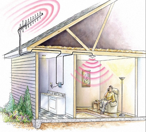
Decimeter waves, unlike all others, work only in line of sight. They are not reflected by the ionosphere as short waves - the ionosphere is transparent to them; they do not bend around obstacles like long waves. The obstacles that they can bypass using their diffraction are comparable to our ordinary objects, that is, they will bypass a person or a stool, but it’s already difficult to bypass a house. But they are reflected from objects that are large for them and can enter, for example, through a window, reflected from a neighboring house. That is, they behave almost like people with hooligan tendencies. What is close and dear to us in its own way.
Self-production
To receive waves whose length is quite commensurate with the objects in our environment, the antenna will be such that it fits into our environment. Consequently, in this regard, it is possible to manufacture not just an undoubtedly useful item, but even a detail that says a lot about the character and tastes of the owner. And which can often be called an architectural detail, and sometimes even a feng shui detail.

The DCM antenna is mounted on a vertical, usually wooden, base rail and consists of several metal parts.
In the direction of the expected passage of the waves, the UHF antenna extends a metal supporting plate, which is called a traverse.
Across it, that is, parallel to the wave front, several resonator plates are installed on it. One is usually active, the antenna wire is taken from it, and placed in the middle. The other two are placed one in front of it (in the direction of the emitter), the other after it. Which in front of him is called the director, his role is to create an obstacle to the wave, forcing it to bend around him, forcing the wave to create a diffraction pattern, that is, the wave to resonate with itself (see the figure at the beginning).

The plate that is placed after the active resonator is called a reflector, that is, a reflector. It reflects the wave back onto the active plate, also amplifying the signal. It is clear that such effects on the wave are possible with strict adherence to the dimensions of the plates, so that they correspond to the lengths of the received waves. The lengths of the plates are made to the size of a half-wave - 0.5 λ. The active element is equal to half a wave, the reflector is a little larger, the director is a little smaller. The distance between the resonators is a quarter wavelength, 0.25 λ.
Often you can see not three plates, but many. This suggests that waves can be received not of one length, but of several lengths. Such antennas are called “multi-wave” or even “all-wave”. But we know that waves are meant only in our decimeter range.
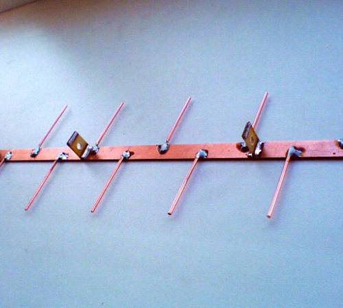
Such antennas can be designed and installed at your own pleasure, taking advantage of the fact that radio waves invisible to us create very intricate patterns of reflections, diffractions and interferences in space. And if you place vibrator plates at the peak points of the waves, you can achieve a good resonance, which will significantly enhance the signal. Using this principle, a log-periodic antenna is built, in which resonators on both sides - right and left - are alternately connected to two buses in a checkerboard pattern.

Two cable buses are connected to two rows of resonators in a staggered pattern
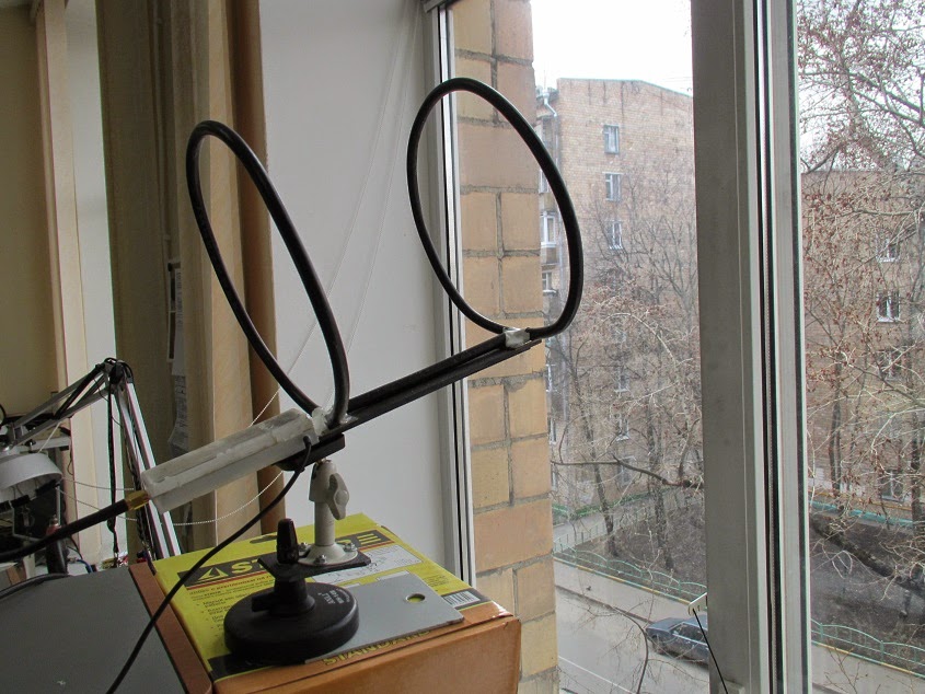
Homemade option
Using scrap materials, you can easily make an indoor antenna - UHF antenna T2. For example, from two computer floppy disks, if you remove the actual magnetic surfaces of the disks from the envelope, you can easily get a Cheburashka antenna - a kind of big-eyed creature, if you have a little imagination.


An external version of the Cheburashka is also possible, then it is worth thinking about a more durable fastening of all parts and cable.


In addition to floppy disks, you also need a stick-stand, a piece of cable and a few nails or screws.
Making your own antenna is a good idea. You don’t have to spend money on buying a finished product, and you don’t want to attract intruders with a beautiful dish or a high-quality radio installation.
If you have a private house or a summer cottage with a small garage, you can make your own television antenna in literally 20-30 minutes. TV is not only a source of information, but also a special atmosphere of comfort and homeliness.
A television antenna is a device specifically designed for receiving broadcast television signals that are transmitted at frequencies from 41 to 250 MHz in the VHF range, and from 470 to 960 MHz in the UHF group.
There are two types of television antennas:
- Internal – located on top or next to the TV;
- External - installed on the roof or attic of the house.
Outdoor antennas are more complex to manufacture and install, but such devices are necessary for adequate reception in peripheral areas remote from television stations.

Antenna devices are also divided into:
- Active, which are complemented by an amplifier and require connection to an electrical power source;
- Passive, which amplify the signal only due to design features.
An outdoor TV antenna is a high input power device and has a unidirectional radiation intensity so its far end must always face the broadcast station.
Based on the wavelength that television antennas are capable of receiving, they are divided into three groups:
- MV antennas - such devices receive very long meter waves, the size of which can be from 0.5 to 1.5 m;
- UHF antennas - these devices operate in the decimeter range, in which the wavelength is in the range from 15 to 40 cm. It is in this coverage that digital television (DTV) is supplied;
- Broadband antennas are a hybrid design in which both VHF and UHF elements are installed. Such radio installations are used to receive digital and analogue broadcasts simultaneously.
![]()
The most commonly used design is an outdoor television antenna based on a log-periodic dipole matrix. Such products consist of several half-wave elements consisting of metal rods. They act as resonators in which energy is stored by radio waves, which cause electrons to move and create stable waves of oscillatory voltage. An antenna can have a different number of rod elements: the more, the higher its gain.
Another popular design, used primarily for UHF reception, is the reflective TV antenna. Such a device consists of a vertical metal screen with several dipole elements installed in front of it.
The television broadcast bands that must be covered by a single antenna are too wide in frequency, so either separate antennas or combined devices are used for the VHF and UHF bands. In such designs there are two types of elements: long elements that pick up the MF (these are located at the rear of the antenna boom and often function as a log-periodic antenna) and short elements that pick up the UHF broadcast (these are located at the front of the boom).

When you listen to the radio, you notice that local channels can be easily tuned in the FM or VHF range, but you won’t be able to catch distant foreign broadcasts on them; to do this, the receiver needs to be switched to MF and HF mode.
This suggests that meter, medium and short waves are well transmitted over long distances, while ultrashort and decimeter signals have a small coverage area. However, the disadvantage of the UHF range in which our digital television operates is minimized thanks to two things:
- Firstly, the presence of a large number of towers;
- Secondly, the ability of large objects to reflect the signal.
If you live in a private house next to a high-rise building, then it is more correct to point the TV antenna not at a distant tower, but at a neighboring house, which perfectly reflects the waves. The right choice of direction largely determines the qualityTV signal.
Materials and calculations
How and from what items and materials can you make an antenna at home? Let's look at the TOP 5 most interesting options:
- Powerful coaxial cable antenna;
- All-wave antenna made of wire;
- "Butterfly";
- "Eight" or zigzag;
- Antenna made from beer cans.
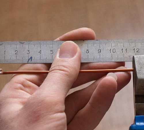
A tube, rod or wire made of copper or aluminum are excellent materials for making an antenna. They are flexible, bend well and hold their shape well. You can use any conductive metal products: wires, corners, rods, strips, etc.

Coaxial cable has the same properties as copper cable, but is much cheaper, and, in addition, coaxial is also mechanically strong, which is important for antenna design. To save money, you can use pieces of wire that are available in your household or buy them in the hardware store.
First of all, let's decide on the size of the antenna. The antenna cable length (L) is calculated depending on the broadcast frequency. To calculate we need two values:
- The speed of wave propagation in vacuum is ≈ 300 million m/s;
- F – reception frequency (digital TV signal frequencies are usually in the range of 500-800 MHz).
If we take the frequency parameter in MHz, then the desired wavelength value will be in meters. The calculated speed of light parameter is 300. The wavelength in the cable can be calculated using a simple formula:

Calculation example: let digital broadcasting be carried out at an average frequency of 610.5 MHz. Then the average wavelength = 300/610.5 = 0.491 m. This is exactly what the length of the antenna loop should be.
To receive a digital signal, it is not necessary to accurately calculate the wavelength; you can simply make the product design more broadband.
Manufacturing and arrangement
Today, all television is presented in digital format; analogue will soon be completely abandoned. Old antennas practically do not function with DVB signals, so you need to create a decimeter antenna.
Digital TV transmission in DVB-T2 format is carried out in the UHF range, and since the signal is broadcast digitally, its reception will always be in good quality, or it simply cannot be caught, and there will be no signal at all. Interference, distortion or unclear picture - this is typical only for analog television.
DVB (Digital Video Broadcasting) encoding is insensitive to electromagnetic interference, however, if the air is heavily polluted, signal mismatch may occur, which can cause the image to freeze or completely crumble. Therefore, it is more efficient to place the antenna outside the house: outside the window, on the roof, on the balcony.

To reduce the amount of interference, a reflector (reflector) can be built behind the antenna. The simplest materials with a metallic tint are suitable for the antenna design: foil, coffee or juice packaging, tin can, CD, etc. In order for the reflector to have a narrowly targeted effect, the shape of the reflector can be made parabolic. Although this is more relevant for analog receivers, reflectors also help out when the digital signal level is weak.
And the last piece of advice: experienced engineers recommend soldering all antenna connections, and not just twisting or screwing them, as over time they will oxidize and affect the quality of reception. It is better to coat external antennas made by yourself with paint; it will more reliably protect your structure from adverse weather factors.
To connect antenna elements, it is better to use soldering machines with a power of 36-40 watts, flux and soft solders.
Coaxial cable antenna
To create this version of the antenna, you will need about 0.5 m of the most common television cable marked “RK-75”. One end of the insulated wire needs to be stripped to connect to the TV socket (put on the F-connector and an adapter for connecting to the TV), and on the second we will create a round antenna.
Step back 5 cm from the edge and remove the top layer of insulating impregnation compound. Then remove the winding from the central conductor of the cable and tightly twist the remaining wire strands into one bundle.
From this point, measure the next 22 cm and cut through the outer layer of insulation to the shielded foil. Now you need to connect the cable into a ring: to do this, we confidently screw the first prepared end to the newly created cut. That's all - you have in your hands a powerful antenna made of coaxial cable, made by yourself.
Connect it to the TV and start tuning channels. This antenna is considered a good option for receiving digital television. It is better to install the antenna outside the window and on the side of the TV tower, since the walls of the building can drown out the desired signal. You can experiment with its position yourself.
All-wave antenna
A TV antenna can have different shapes. For example, from copper wire with a diameter of 2-5 mm, you can build an all-wave antenna in the form of two versatile elements. Such devices are frequency independent, so they are very popular among summer residents. A CHNA device can be built in literally an hour and receive a good signal level far from television centers.
For this you will need:
- Enameled copper wire;
- 2 metal structures in the shape of an isosceles triangle;
- 2 wooden or plastic slats.
Instead of metal triangles, you can use elastic foil laminate, from which you will need to cut the triangles (or leave the copper coating in a triangular shape).

The width and height of the antenna must be identical. The blades are installed at right angles and fixed with a soldering iron. The CNA antenna cable must be laid to the point of zero potential, which is located at the intersection of the cable with the vertical guide. Moreover, it must be tied with a tie, and not soldered.
The distance between adjacent wire threads should be 25-30 mm, and between the plates - no more than 10 mm. It is better to install the antenna structure inside the window at 150 cm. The signal catcher in the form of two expanded elements, which you just made yourself, will confidently receive all UHF and HF channels. If you live in an area with poor signal levels, it would be advisable to supplement such a device with an amplifier.
A simple antenna for receiving digital TV
Another useful type of home antenna for the dacha is the “butterfly”. This is a very simple design, to create which you will need:
- Board or plywood about 60 cm long and 7 cm wide, thickness about 20 mm;
- Shielded copper wire with a 4 mm core cross-section;
- Coaxial cable “RK-75”;
- Washers, screws, soldering iron.
Below we provide a marking diagram according to which you need to make the base of the butterfly antenna.

After this, prepare 8 pieces of copper wire, each 37.5 cm long. Step back 17.75 cm and remove 2 cm of the insulating layer in the center of each piece. Give them a V-shape so that the ends of the elements are at a distance of 7.5 cm from each other (this shape is considered optimal for high-quality and clear TV signal reception).
The next step is to prepare two more wire elements about 22 cm long. Mark each element into 3 equal parts and strip the wire insulation between the resulting sections.
We will need two more small pieces of wire to connect the antenna to the socket.
Now all that remains is to simply assemble all the prepared elements into a single structure and solder the cable to the plug.
This is how you can easily make your own effective butterfly antenna for receiving digital television.
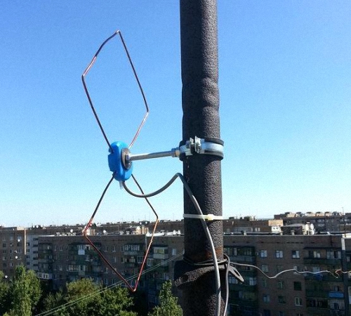
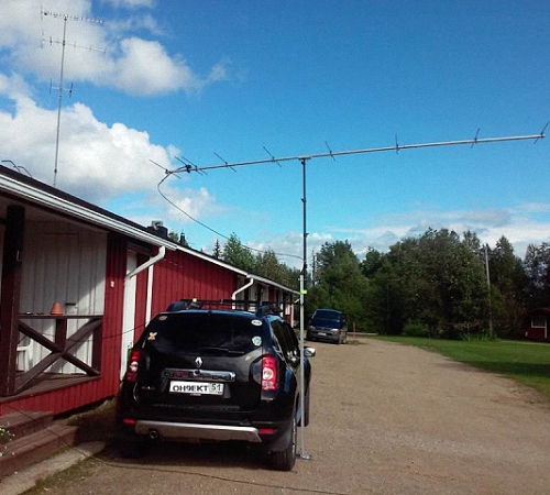
Figure-of-eight antenna
The next option for creating a simple UHF television antenna is named after the shape of its design, “figure eight” or “zigzag”. Such a device will reliably pick up the signal even in a remote village.
In order to make an outdoor antenna for digital television with your own hands, you will need:
- Amplifier (you can use any old one);
- 2 pieces of copper wire (180 cm each);
- Plate (wood or metal) 15*15;
- TV cable;
- Iron mast for raising the antenna.

First of all, we create the body of the catcher: from copper wire we form two rhombuses with an optimal side size of 45 cm each. We attach the ends of the two elements to the plate: we form a ring from the core and slightly flatten it, screw it with bolts or solder it using a soldering machine.
We connect the amplifier and insert the cable plug into the connector. In general, that's all. All that remains is to install the finished structure on an elevated mast, which must be firmly dug into the ground.
To make an outdoor antenna for a TV, any conductive material of the appropriate cross-section is suitable: copper or aluminum tubes, strips or a profile element with a thickness of 1 to 5 mm. The main thing is to give the antenna body the correct shape.
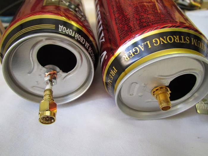
Beer can antenna
Ether antenna devices can be created from many simple materials that are used in household use, even from ordinary cans in which carbonated drinks are sold. Such a mini-receiver will not be very powerful, but you can pick up about 7 channels, not only in the UHF range, but also in the longer one - VHF.
There is one important condition: the cans must be smooth, not ridged, clean and dry. The essence of this design is very simple: you just need to solder 2 cans to the cable and place them on opposite sides on a wooden base.

The number of cans can be used differently; it is believed that it is optimal to create 3 or 4 lines of cans, since 1-2 lines pick up the signal weakly, and more than 5 lines are difficult to coordinate. In addition to cans, you need to prepare the following materials:
- About 5 meters of ordinary TV cable marked “RK-75”;
- Wooden or plastic base structure;
- Several self-tapping screws, electrical tape, and a soldering iron.
First you need to prepare the TV cable: step back 10 cm from the edge, make a shallow cut and remove the top layer of insulation. Carefully twist the inner braided screen into a single bundle. On the same side of the cable, remove the plastic insulation and expose the central core. A plug must be connected to the opposite end of the cable.
Next, we will need to connect the coaxial cable to the banks. To do this, it is better to use small flea screws for drywall: screw a twisted cable braid to one can, and a copper core to the second can. For better contact, connections can be soldered.
Now you should secure the cans to a wooden base plate. This can be done using ordinary adhesive tape, electrical tape or a glue gun; you can even use an ordinary clothes hanger or any flat structure at hand. The main thing is that the metal cans are of the same shape, the same size (volume) and are located strictly on the same line. The distance between the sheet metal elements, as well as the location of the antenna installation, is selected experimentally.
You can improve the design by creating a grid of several lines with banks, and if there is such an opportunity, then connect an amplifier. If a homemade antenna made from beer cans is placed on the street, then its elements will have to be hidden in larger plastic bottles.
The length of the cable affects the signal attenuation: the longer the cord, the more the on-air transmission is attenuated. This is especially true for receiving meter waves.
Setting up and searching for channels
Today, digital television offers us as many as 22 television channels in two packages, and in some metropolitan areas there are even more. Setting them up on your TV or set-top box will be quite simple.
In DTV broadcast on 1 frequency, not one channel is broadcast, as it once was on analogue broadcast, but up to 10 channels in one package or multiplex. For example, on frequency 43 you can receive 10 TV channels and 3 radio stations. Therefore, setting up digital broadcasting uses only 2 frequencies. However, the frequency parameter of the channels will be different for different areas.

If you are using a home-made antenna in an area with good signal strength, then there are no special recommendations for setting up channels. You simply turn on the function on your TV "Automatic channel search" and the receiver finds all available channels in digital and analogue air.
If the area of your location is not very favorable for TV broadcasting, and the auto search did not produce results, then you need to perform the following steps:
- Check which direction your antenna is facing. It should be turned towards the television tower or directed towards the nearest high-rise building. If you don't know which way the broadcast base is located, pay attention to your neighbors' antennas (but don't look at the satellite dishes that pick up signals from satellites).
- In channel settings, set a restriction: search only for digital channels (or DTV). Well, if you know the frequency parameter, then you can go into the manual channel tuning mode, use the remote control to dial the channel number on which the package is being broadcast, and a signal level scale in percentage should appear on the display. Change the position of the antenna device and see how the stability of this indicator changes.
The change in signal level when rotating the antenna will not change instantly, but after 5-10 seconds. Therefore, pause when changing the position of the catcher.
When you get the best signal strength, start scanning for digital channels and save your settings. Perform the same algorithm of actions to search for the second multiplex. If the situation is completely sad and not a single method has yielded results, you may need to make the design of your antenna more powerful or supplement it with an amplifier.
Currently, almost all television broadcasting has switched to broadcasting in the decimeter range. This is due to the fact that waves in this range are insensitive to the influence of external interference and the equipment used to ensure broadcasting in this range has low cost. It was chosen as the range for using T2 digital television.
Decimeter waves (UHF) are located in the range of radio waves having a wavelength from one meter to 10 cm, and lie in frequencies from 300 MHz to 3 GHz. To receive UHF, broadband directional antennas are used; they can receive TV broadcasts at a distance of 60-70 km from the television center.
Features of UHF reception
It is necessary to understand that there is no clear difference between professional and home antennas. Professional antennas for television mode have a narrow radiation pattern, which means a higher gain. Thanks to this they have more complicated, with many design elements than homemade ones.
We list the main parts that make up the antenna:
- feeder;
- reflector;
- vibrator;
- director.

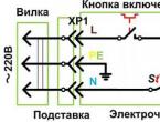
In the vicinity of the transmitter, the antenna can be placed indoors or outdoors. In the distance, of course, you need to place it outside: on a wall, balcony, roof, mast. Usually away from repeater the antenna is placed at a height of 8-15 m on the mast.
Balancing antennas
 Balancing devices are eliminated ingress of currents radio frequencies to the outer area of the outer conductor (braid) of the coaxial wire. It is impossible to connect without such a device, as this leads to curvature of the antenna radiation pattern and a decrease in reception noise immunity. When the input impedance of the antenna differs from the characteristic impedance of the wire, then such a device is also used as a matching device.
Matching device It’s not difficult to do it yourself for an antenna. Usually a quarter-wave bridge or a wave U-elbow is used. The bridge is a two-wire short-circuited line with a length of Lcp/4, connected to the vibrator terminals. The bridge consists of two tubes, an insulator and a short-circuited shunt. A cable is passed through one of the tubes (for example, the left one). The outer conductor (braid) is connected to the left tube of the vibrator and the left tube of the bridge, the central contact - to the right vibrator tube.
The wave bend is made of cable and consists of two sections with a characteristic impedance of 75 Ohms, respectively, lengths Lc/4 and Lc/3, where Lc is the average wavelength in the cable. Withstand certain distance no need between cables. The operating frequency band is 12-15 percent.
And can also be used wire transformer. It transforms the antenna's input impedance to an impedance of 73 ohms. Two pairs of transformer coils are wound alternately on two frames with a diameter of 5-7 mm. The winding is continuous, in two wires. The gap between the frames is 15-20 mm. Installation is carried out on a metal board, to the ends of which the feeder braid and the ends of the windings are soldered.
Wire antenna
The simplest design can be made from piece of copper wire. Such an antenna is a loop frame, which consists of two conductors separated by a gap. In the case of using a mast, fastening is carried out using an insulating plate, for example, getinaks, varnished or textolite. When used outdoors, the cable connection point should be protected from direct exposure to precipitation.
The main operation will be to calculate the length of the loop. To do this, you need to know the transmission frequency of the broadcast signal. The wavelength corresponding to the image carrier frequency f is calculated by the formula L = 300/f. For example, for a frequency of 600 MHz this value will be L = 300/600 = 0.5 m. That is, the loop length will be 50 cm.
Aluminum disc
For production we will need:
- aluminum disk 1 mm thick;
- printed circuit board made of fiberglass 1 mm thick;
- matching transformer;
- cable with characteristic impedance 75 Ohm.
In an aluminum disk with a diameter of 356 mm, with a hole in the middle with a diameter of 170 mm, a 10 mm cut is made. Instead of a sawn piece, a printed circuit board is installed, to which a matching transformer is soldered. Instead, you can install an amplification device taken from the kit that comes with the Polish antenna.
Wave channel
 A simple design, highly efficient directional antenna that can be used in almost the entire television broadcast range. The antenna is an active half-wave vibrator (usually a loop), a reflector of several directors mounted on the base of the boom, fixed with staples or welding. The vibrator with the boom is fixed to the mast. Connection of cable and balancing-matching U-shaped elbow to active vibrator produced using a special box.
A half-wave elbow is made from sections of coaxial cable with a length equal to the average wavelength divided by two. The U-elbow is both a balun and a resistance transformer: it changes the input impedance loop vibrator 292 Ohm to 73 Ohm, which makes it possible to ensure coordination of the vibrator with the feeder. The braids of the elbow cable must be soldered together, as well as with the braid of the feeder. The length of the piece of wire used will be approximately 185 mm.
Calculation
UHF antenna vibrators are made of tubes with a diameter of 14 to 25 mm, the supporting boom is 18-35 mm. The mast can be made of tubes with a diameter of 40-50 mm, with a wall of 3-4 mm, or a wooden beam 60x60 mm.
The distance between the elements of the device can be calculated in programs specially created for this: Antwu 15, 4K6D, etc. These Russified utilities, it won't be difficult to figure it out.
Zigzag device
 An easy-to-manufacture wide-range antenna. Operates in double frequency band. The design consists of two vertical slats mounted on a dielectric stand. Steel strips are attached to the upper and lower ends of the rack. Planks of the same type, but through insulating washers, are fixed to the ends of the slats. On the stand between the slats there is a non-conductive plate on which two conductor plates.
A cable with a diameter of 3-4 mm is connected to steel strips. It is also soldered to the bottom bar. The wire is laid parallel to the side of the inner cable of the lower frame and soldered to the strips (braided on the left, center conductor on the right).
To simplify the design, you can use only one diamond, a zigzag. The size of such a rhombus will be 340x340 mm. The distance between two metal strips in the center of the diamond is about 10 mm. The material used is aluminum, copper or brass tubes, or strips 6-10 mm wide.
Amplifier
To improve television reception, an antenna with an active signal amplifier is often used. Typically, such an amplifier does not need tuning and is made using low-noise transistors with a gain of about 20 dB.
In order to make a TV signal amplifier with your own hands, you will need a printed circuit board and the following list of radio elements:
- Resistors: R1, R5-220 Ohm; R2, R6-8.2 kOhm; R3-3.3 kOhm; R4, R8-22 Ohm; R7- 1.5 kOhm.
- Capacitors: C1-0.01 uF; C2, C4, C6-220 pF; C3, C5-100 nF.
- Transistors: VT1, VT2 S790T.
The antenna amplifier circuit for a TV with your own hands will look like this:
https://masterkit.ru/images/magazines/3_SH3 04 .gif
 The amplifier is made using S790T transistors according to a common emitter circuit and has two correction chains R1, C3 and R5, C5. The device is assembled on two amplification stages. The central core of the input cable is soldered to the input of capacitor C2, and the screen braid is soldered to the common ground. The amplified signal is removed from the output of capacitor C6.
The amplifier for the antenna is soldered on a separate independent board, and the radio elements on it are mounted using a hinged method. The board is mounted in the middle of the antenna, this arrangement allows you to effectively receive the signal.
Loop antenna
A homemade device will consist of the following elements:
- aluminum strips measuring 320 mm;
- mast;
- reflector;
- amplification device;
- cable.
First, a frame of four strips is assembled. Fastening to each other is carried out using screws. A cross is installed in the middle of the frame. From the center, each part of the cross is shortened by 5 mm. The parts of the cut plates closest to each other are connected by a conductor, forming two internal, separated squares. The cable is soldered to these plates, the central core to one, the braid to the other. Next, the antenna is installed on the mast, and the amplifier is attached.
Log-periodic
This antenna is distinguished by its good coordination with coaxial cable and narrow radiation pattern, which allows receiving a television signal at a considerable distance.
The antenna consists of a two-wire symmetrically distributed line formed from identical tubes lying parallel to each other. Seven semi-vibrators are installed on these tubes, and their direction alternates to the opposite direction relative to the previous one.
A cable with a characteristic impedance of 75 Ohms is laid in one of the lines, the ends of the pipes at the feeder entry point are connected by a conductor plate. The cable screen is soldered when it leaves the line, and the central core is soldered to a petal mounted on the plug of another pipe. Distance between vibrators choose from the beginning 80, 94.77, 63, 52, 43, 35 mm, and their sizes are 160, 131, 107, 88, 72, 60, 49 mm, respectively.
Polish
If you don’t have the opportunity or desire to make an amplifier yourself, you can purchase a ready-made one. Particularly popular are those found in so-called Polish antennas, for example, from Sowar. The Polish antenna operates in the broadband range, i.e. it can receive UHF and meter signals. However, in the form in which it exists, it is not very suitable for receiving DVB-T digital television, so modifications are recommended for its use.
The thing is that the input impedance of the amplifier is higher than the impedance of the antenna. To begin with, we remove the long meter-long active vibrators or shorten them to decimeter sizes, then remove the reflector sheet from the active vibrators. Thus, the antenna resistance changes. It is advisable to remove the matching unit, a ferrite ring, from the amplifier. This will help expand the range, increase the resistance, and change the frequency response.
Canning
This original antenna, which is easy to make yourself, is not inferior in parameters to a log-periodic antenna. It is assembled from two tin cans. Cans are taken with dimensions of 75x95 mm. Using two strips of fiberglass, the cans are connected by soldering. One strip is solid, and on the second there is a gap into which the cable is soldered. Its operating principle is based on the property of a symmetrical broadband vibrator, due to which it has a high gain.
The types of antennas considered can be easily connected to all kinds of set-top boxes for receiving digital television and even FM.