Isotopic composition of gases of helium-neon laser. Gas helium-neon laser. Procedure for performing laboratory work
JOB 17. STUDYING THE CHARACTERISTICS OF LASER RADIATION
GOAL OF THE WORK:
1. Familiarize yourself with the principle of operation and the device of a helium-neon laser.
2. Get acquainted with the interference, diffraction and polarization of laser radiation.
3. Determine the periods of the two-dimensional structure.
4. Determine the angle of divergence of the laser beam.
BRIEF THEORY
The laser is a fundamentally new light source. Laser radiation differs from the radiation of conventional sources (incandescent lamps, fluorescent lamps, etc.) in that it is close to monochromatic, has exceptionally high temporal and spatial coherence, and very low divergence , and, consequently, an exceptionally high density of electromagnetic energy. In addition, the laser beam is polarized.
The operating principle of a laser is based on three physical phenomena: stimulated emission, population inversion, and positive feedback.
The behavior of atoms (molecules) obeys the laws of quantum mechanics, according to which the values of physical quantities (for example, the energy E) can only take certain (discrete) values. For energy, these values are usually depicted graphically in the form of so-called energy levels (Fig. 1).
The lowest energy level is called the ground level because it corresponds to the most stable state of the particle. The remaining levels with higher energy values are called excited.
A process accompanied by an increase in the energy of an atom is depicted as a transition to a higher energy level, a process with a decrease in energy - as a transition to a lower level.
Consider the interaction of electromagnetic radiation (light) with atoms.
The first type of interaction: an atom, being in the ground state, absorbs a photon whose energy is sufficient for a transition to one of the excited states (Fig. 1a).
And second: an atom in an excited state,
spontaneously (spontaneously) passes into a lower energy state: this transition is accompanied by the emission of a photon (Fig. 1c).

During spontaneous transitions, different atoms emit non-simultaneously and independently, therefore, the phases of the emitted photons are not interconnected, the direction of radiation, its polarization are random, and the frequency of radiation varies within certain limits determined by the width of the energy levels E 1 and E 2.
Spontaneous radiation is non-directional, non-polarized, non-monochromatic.
There is, however, third type of interaction, which is called stimulated emission. If an atom in an excited state (Fig. 2) is exposed to radiation with a frequency ν corresponding to the transition of an atom to a lower state (1), then the atom is forced into it under the action of this photon, while emitting its own photon, which is called stimulated emission.

It is extremely important to note the characteristic property of stimulated emission: the emitted wave (photon) has exactly the same direction and phase which is compelling. In addition, these two waves have the same frequencies and polarization states.
During transitions 1→2 (Fig. 1a), external radiation is absorbed, and during forced transitions 2→1 (Fig. 2), on the contrary, it is amplified, because the photon emitted by the atom is added to the external photon. The transition probabilities 1→2 and 2→1 are the same. If most of the atoms are in an excited state, then 2 → 1 transitions will occur more often . In other words, to amplify the external radiation, it is necessary that population level 2 population was higher than level 1 population or it is necessary to create inversion level populations.
At temperature T, the number of atoms N in a state with energy E is determined by the Boltzmann formula
N~exp(-E/kT)
where k is the Boltzmann constant.
This shows that the greater the energy of the state E, the smaller the number N of atoms in this state. This means that in the equilibrium state the lower levels are more populated, and the absorption of light prevails over the amplification.
The population inversion of the levels corresponds to the nonequilibrium state of the atoms of the medium.
Such a state can be created artificially by summing up
energy to the working substance, due to which the atoms are transferred to the upper energy level. Such a process is called pumped. In different types of lasers, pumping is carried out in different ways: in solid-state lasers, it is carried out by absorbing light from additional lamps, in gas lasers, by transferring the energy of electrons accelerated by an electric field to gas atoms during their collisions.
The medium in which the population inversion is carried out is called the active medium.

The word "laser" is made up of the initial letters of the English phrase: "Light Amplification by Stimulated Emission of Radiation", which means: "light amplification by stimulated emission". Lasers are also called optical quantum generators (OQGs).
gas lasers. Helium-neon laser.
The main element of a helium-neon CW laser
action is tube 2 (Fig. 3), filled with a mixture of helium and neon with partial pressures of the order of 1 and 0.1 mm Hg, respectively. The ends of the tube are closed with plane-parallel glass plates 3 set at the Brewster angle to its axis.
Pumping in a gas laser is carried out due to the energy of the power source that maintains a glow discharge between cathode 4 and anode 5. The discharge in the tube occurs at 1.5-2.0 kV. The discharge current of the tube is tens of milliamps.
The working atoms of a helium-neon laser are atoms
neon emitting red photons (λ = 632.8 nm), Fig. Figure 4 shows a simplified diagram of the levels of neon and helium atoms.
In pure neon, the population of the 3S states during pumping is inefficient, since this level has a short lifetime, and the neon atom spontaneously transforms into the 2P state.
The situation changes when helium is added to neon. The energy of the 2S level of helium is equal to the energy of the 3S level of neon. On the other hand, the 2S energy level of helium is long-lived and is efficiently populated upon pumping. When excited helium atoms collide with neon atoms, energy is transferred to neon atoms. As a result, an inverse population of the working level 3S of neon is created.
 |
After that, numerous
acts of spontaneous transitions 3S→2P, appearing photons (λ = 632.8 nm) lead to forced transitions. Those photons that move at some angle to the axis of the tube do not participate in obtaining the laser beam. The laser beam is formed only by photons emitted along the axis of the tube.
The amplification of the beam goes much faster if the light is returned back to the active medium, where it will again be amplified due to forced transitions. This situation is referred to as feedback. To create positive feedback in lasers, an optical resonator is used, which consists of two mirrors 1 (Fig. 3).
The increase in the intensity of stimulated emission occurs like an avalanche, and it becomes much greater than the intensity of spontaneous emission, which can be ignored in what follows.
The generation of a laser beam begins at the moment when the increase in the radiation energy due to stimulated transitions exceeds the energy loss for each pass of the resonator. To output the beam from the resonator, one of the mirrors 1 is made translucent. The surfaces of both mirrors are covered with films, the thickness of which is chosen in such a way that waves of the desired wavelength are reflected, and all others are extinguished.
The transparency of the resonator mirrors is usually less than 1%.
Characteristics of laser radiation.
Similar information.
The helium-neon laser - along with the diode or semiconductor - is one of the most commonly used and most affordable lasers for the visible region of the spectrum. The power of laser systems of this kind, intended mainly for commercial purposes, is in the range from 1 mW to several tens of mW. Particularly popular are less powerful He-Ne lasers of the order of 1 mW, which are used mainly as quoting devices, as well as for solving other problems in the field of measuring technology. In the infrared and red ranges, the helium-neon laser is increasingly being replaced by the diode laser. He-Ne lasers are capable of emitting orange, yellow and green lines in addition to red lines, which is achieved thanks to appropriate selective mirrors.
Energy Level Diagram
The energy levels of helium and neon that are most important for the function of He-Ne lasers are shown in Figs. 1. Laser transitions occur in the neon atom, with the most intense lines resulting from transitions with wavelengths of 633, 1153, and 3391 (see Table 1).
The electronic configuration of neon in the ground state looks like this: 1 s 2 2s 2 2p 6 and the first shell ( n= 1) and the second shell ( n= 2) are filled with two and eight electrons, respectively. Higher states according to fig. 1 arise as a result of the fact that there is 1 s 2 2s 2 2p 5 is a shell, and a luminous (optical) electron is excited according to the scheme: 3 s, 4s, 5s,..., Z R, 4R,... etc. We are talking, therefore, about the one-electron state, which carries out the connection with the shell. In the LS scheme (Russell-Saunders), for the energy levels of neon, a one-electron state is indicated (for example, 5 s), as well as the resulting total orbital momentum L (= S, P, D...). In the notation S, P, D, ... the lower index shows the total orbital momentum J, and the upper one shows the multiplicity 2S + 1, for example, 5 s 1 P 1 . Often, a purely phenomenological designation according to Paschen is used (Fig. 1). In this case, the sublevels of excited electronic states are counted from 2 to 5 (for s-states) and from 1 to 10 (for p-states).
Excitation
The active medium of a helium-neon laser is a gas mixture, to which the necessary energy is supplied in an electric discharge. The upper laser levels (2s and 2p according to Paschen) are selectively populated on the basis of collisions with metastable helium atoms (2 3 S 1 , 2 1 S 0). During these collisions, not only the exchange of kinetic energy occurs, but also the transfer of energy from excited helium atoms to neon atoms. This process is called a collision of the second kind:
He* + Ne -> He + Ne* + ΔE, (1)
where the asterisk (*) symbolizes the excited state. The energy difference in the case of excitation of the 2s level is: &DeltaE=0.05 eV. In a collision, the existing difference is converted into kinetic energy, which is then distributed in the form of heat. For the 3s level, identical relationships take place. Such a resonant energy transfer from helium to neon is the main pumping process in creating a population inversion. In this case, the long lifetime of the metastable state He has a favorable effect on the selectivity of the population of the upper laser level.
The excitation of He-atoms occurs on the basis of the collision of electrons, either directly or through additional cascade transitions from higher levels. Owing to long-lived metastable states, the density of helium atoms in these states is very high. The upper laser levels 2s and 3s can - subject to the selection rules for electrical Doppler transitions - pass only to the lower p-levels. For successful generation of laser radiation, it is extremely important that the lifetime of s-states (upper laser level) = approximately 100 ns exceeds the lifetime of p-states (lower laser level) = 10 ns.
Wavelengths
Next, we will consider the most important laser transitions in more detail, using Fig. 1 and data from Table 1. The best known line in the red region of the spectrum (0.63 μm) is due to the transition 3s 2 → 2p 4 . The lower level is split as a result of spontaneous emission during 10 ns into the 1s level (Fig. 1). The latter is resistant to splitting due to electric dipole radiation, so that it has a long natural life. Therefore, atoms are concentrated in this state, which turns out to be highly populated. In a gas discharge, atoms in this state collide with electrons, and then the 2p and 3s levels are again excited. In this case, the population inversion decreases, which limits the laser power. The depletion of the ls-state occurs in helium-neon lasers mainly due to collisions with the wall of the gas-discharge tube, and therefore, with an increase in the tube diameter, a decrease in gain and a decrease in efficiency are observed. Therefore, in practice, the diameter is limited to about 1 mm, which, in turn, limits the output power of He-Ne lasers to several tens of mW.
The electronic configurations 2s, 3s, 2p, and 3p participating in the laser transition are split into numerous sublevels. This leads, for example, to further transitions in the visible region of the spectrum, as can be seen from Table 2. For all visible lines of the He-Ne laser, the quantum efficiency is on the order of 10%, which is not very high. The level diagram (Fig. 1) shows that the upper laser levels are approximately 20 eV above the ground state. The energy of red laser radiation is only 2 eV.
Table 2. Wavelengths λ, output powers, and line widths Δ ƒ of a He-Ne laser (Paschen transition notation)
| Color | λ nm |
Transition (according to Pashen) |
Power mW |
Δ ƒ MHz |
Gain %/m |
| Infrared | 3 391 | 3s 2 → 3p 4 | > 10 | 280 | 10 000 |
| Infrared | 1 523 | 2s 2 → 2p 1 | 1 | 625 | |
| Infrared | 1 153 | 2s 2 → 2p 4 | 1 | 825 | |
| Red | 640 | 3s 2 → 2p 2 | |||
| Red | 635 | 3s 2 → 2p 3 | |||
| Red | 633 | 3s 2 → 2p 4 | > 10 | 1500 | 10 |
| Red | 629 | 3s 2 → 2p 5 | |||
| Orange | 612 | 3s 2 → 2p 6 | 1 | 1 550 | 1.7 |
| Orange | 604 | 3s 2 → 2p 7 | |||
| Yellow | 594 | 3s 2 → 2p 8 | 1 | 1 600 | 0.5 |
| Yellow | 543 | 3s 2 → 2p 10 | 1 | 1 750 | 0.5 |
Radiation in the infrared range around 1.157 µm arises through transitions 2s → 2p. The same applies to a slightly weaker line at about 1.512 µm. Both of these infrared lines find use in commercial lasers.
A characteristic feature of the line in the IR range at 3.391 μm is a high gain. In the zone of weak signals, that is, with a single passage of weak light signals, it is about 20 dB / m. This corresponds to a factor of 100 for a 1 meter long laser. The upper laser level is the same as for the known red transition (0.63 µm). The high gain, on the one hand, is caused by the extremely short lifetime at the lower 3p level. On the other hand, this is due to the relatively long wavelength and, accordingly, the low frequency of radiation. Usually the ratio of stimulated and spontaneous emissions increases for low frequencies ƒ. The amplification of weak signals g, as a rule, is proportional to g ~ƒ 2 .
Without selective elements, the He-Ne laser would emit at the 3.39 µm line and not in the red region at 0.63 µm. The excitation of the infrared line is prevented either by the selective cavity mirror or by absorption in the Brewster windows of the gas-discharge tube. Due to this, the laser generation threshold can be raised to a level sufficient for 3.39 μm radiation, so that only a weaker red line appears here.
Design
The electrons necessary for excitation are formed in a gas discharge (Fig. 2), which can be used with a voltage of about 12 kV at currents from 5 to 10 mA. The typical length of the discharge is 10 cm or more, the diameter of the discharge capillaries is about 1 mm and corresponds to the diameter of the emitted laser beam. As the diameter of the gas discharge tube increases, the efficiency decreases, since collisions with the tube wall are required to empty the ls level. For optimum power output, the total filling pressure (p) is used: p·D = 500 Pa·mm, where D is the diameter of the tube. The He/Ne mixture ratio depends on the desired laser line. For the known red line, we have He: Ne = 5:l, and for the infrared line of about 1.15 µm - He:Ne=10:l. An important aspect is also the optimization of the current density. The efficiency for the 633 nm line is about 0.1%, since the excitation process in this case is not very efficient. The service life of a helium-neon laser is about 20,000 operating hours.
|

Rice. 2. Design of a He-Ne laser for polarized radiation in the mW range
The gain under these conditions is at g=0.1 m -1 , so it is necessary to use highly reflective mirrors. To exit the laser beam, a partially transmissive (semitransparent) mirror (for example, with R = 98%) is installed there on one side only, and on the other side, a mirror with the highest possible reflectivity (~ 100%). The gain for other visible transitions is much less (see Table 2). For commercial purposes, these lines have been obtained only in recent years with the help of mirrors, which are distinguished by extremely low losses.
Previously, in a helium-neon laser, the output windows of the discharge tube were fixed with epoxy resin, and the mirrors were mounted outside. This caused helium to diffuse through the adhesive and water vapor entered the laser. Today, these windows are fastened by direct welding of metal to glass, which reduces helium leakage to about 1 Pa per year. In the case of small, mass-produced lasers, the mirror coating is applied directly to the output windows, which greatly simplifies the entire design.
Beam Properties
To select the direction of polarization, the gas-discharge lamp is equipped with two obliquely arranged windows or, as shown in Fig. 2, a Brewster plate is inserted into the resonator. The reflectivity on an optical surface vanishes if the light is incident at the so-called Brewster angle and is polarized parallel to the plane of incidence. Thus, radiation with this direction of polarization passes without loss through the Brewster window. At the same time, the reflectivity of the component polarized perpendicular to the plane of incidence is quite high and is suppressed in the laser.
The ratio (degree) of polarization (the ratio of power in the direction of polarization to the power perpendicular to this direction) is 1000:1 for conventional commercial systems. When a laser operates without Brewster plates with internal mirrors, unpolarized radiation is generated.
The laser usually generates in the transverse TEM 00 mode (the lowest order mode), and several longitudinal (axial) modes are formed at once. When the distance between the mirrors (length of the laser resonator) L = 30 cm, the intermode frequency interval is Δ ƒ` = c/2L = 500 MHz. The central frequency is at the level of 4.7·10 14 Hz. Since amplification of light can occur within the range Δ ƒ = 1500 MHz (Doppler width), three different frequencies are emitted at L = 30CM: Δ ƒ/Δ ƒ`= 3. When using a smaller distance between the mirrors (<= 10см) может быть получена одночастотная генерация. При короткой длине мощность будет весьма незначительной. Если требуется одночастотная генерация и более высокая мощность, можно использовать лазер большей длины и с оснащением частотно-селективными элементами.
Helium-neon lasers around 10 mW often find use in interferometry or holography. The coherence length of such mass-produced lasers is from 20 to 30 cm, which is quite sufficient for holography of small objects. Larger coherence lengths are obtained by using serial frequency-selective elements.
When the optical distance between the mirrors changes as a result of thermal or other effects, the axial natural frequencies of the laser resonator are shifted. With single-frequency generation, a stable radiation frequency is not obtained here - it moves uncontrollably in the linewidth range of 1500 MHz. By additional electronic control, frequency stabilization can be achieved just in the center of the line (commercial systems can have a frequency stability of several MHz). In research laboratories, it is sometimes possible to stabilize a helium-neon laser to a range of less than 1 Hz.
By using suitable mirrors, the different lines from Table 4.2 can be excited to generate laser light. The most commonly used visible line is around 633 nm with typical powers of several milliwatts. After suppression of an intense laser line of about 633 nm, other lines in the visible range can appear in the resonator due to the use of selective mirrors or prisms (see Table 2). However, the output powers of these lines are only 10% of the output power of a heavy line or even less.
Commercial helium neon lasers are available in a variety of wavelengths. In addition to them, there are also lasers that generate on many lines and are capable of emitting waves of many wavelengths in various combinations. In the case of tunable He-Ne lasers, it is proposed to select the required wavelength by turning the prism.
Gas helium-neon lasers (He-Ne lasers) manufactured by the German company LSS have a robust design, good beam quality and a long service life - up to 20,000 hours. The helium-neon laser series is represented by a wide variety of laser models, single-mode and multi-mode, with an output power from 0.5 to 35 mW, emitting in the spectral range of red, green and yellow. There are also Brewster window laser tubes for educational and scientific purposes.
All models are equipped with a power supply. Gas ion argon lasers of the LGK series meet an impressive list of world standards and are certified by CDRH, IEC, CSA, CE, TUV, UL. LSS provides efficient support for worldwide lasers of its own production, providing its customers with a convenient and fast service for the replacement of laser tubes. In addition to serial models, the company produces custom-made laser systems.
The helium neon laser is designed for a wide range of applications such as scanning microscopy, spectroscopy, metrology, industrial measurement, positioning, alignment, aiming, testing, code verification, scientific, basic and medical research, as well as for educational purposes.
Specifications of laser modules
The tables below show the key characteristics of the lasers. For all items below, the specifications listed are the overall performance of the standard models. Individual characteristics can be optimized for specific applications. Please contact our company consultant if you have special requests.

Specifications of laser tubes


Power Supply Specifications
All models of gas ion argon lasers of the LGK series are equipped with a power supply unit manufactured by LSS.


Fundamentals of laser physics
The word "Laser" is composed of the first letters of the English phrase "Light Amplification by Stimulated Emission of Radiation" - amplification of light by induced radiation.Helium-neon laser (design and principle of operation)
The He-Ne laser uses the principle of resonant transfer of excitation energy from the impurity gas (He) to the main gas (Ne). The energy level diagram for helium and neon is shown in fig. 7.5.For a given mixture of gases, the conditions for resonant energy transfer are satisfied for the levels
2 1s (He) → 3s (Ne) , 2 3s (He) → 2s (Ne)
As a result of the gas discharge, the levels 2 1 s and 2 3 s are populated by electron impacts. In inelastic collisions of excited helium atoms with neon atoms, the latter are excited and the metastable levels 2s and 3s are populated:
He * + Ne → He + Ne * (2s) + Ne * (3s)
Although the 2p and 3p levels of neon are also populated by electron impacts, which reduces the population difference between the 2s, 3s and 2p, 3p levels, the efficiency of this process is low compared to process (7.11). This is achieved by the fact that the partial pressure of neon (~10 Pa) is much less than the partial pressure of helium (~100 Pa), in connection with which the helium concentration significantly exceeds the neon concentration.
Due to the level energy defect (2 1 s → 2s), which significantly exceeds kT, the result of process (7.11) is far from desirable. However, this is compensated by the longer lifetime of excited Ne atoms at the 2s and 3s levels, which consist of four sublevels, as compared to the 2p and 3p levels. For example, the lifetime of neon at the 2s 2 level is 9.6 * 10 -8 s, and the lifetime at the 2p 4 level is 1.2 x 10 -8 s.
When the inverse population of the 2s and 3s levels occurs, radiative transitions to the 2p and 3p levels occur with the following wavelengths:
2s 2 → 3p 4 λ 2 = 3.39 µm
3s 2 →2p 4 λ 3 = 0.6328 µm
The “spent” atoms pass through spontaneous emission from the levels 3p and 2p to the metastable level 1s. The sink of particles from the 1s level is provided mainly by diffusion to the walls.
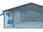
The scheme of the gas laser design is shown in fig. 7.6.

In a gas-discharge tube filled with a mixture of neon and helium in a ratio of 1:10, a gas discharge is ignited, with the help of which the level population is inverted.
Since photons with arbitrary frequencies appear during the discharge, there are also photons with wavelengths λ 1 , λ 2 and λ 3 that coincide with the wavelengths of the corresponding transitions. They cause an induced transition with the formation of photons with the same frequencies, phases and directions of wave vectors k ". If a wave appears with a frequency, for example, ω 3 \u003d c / λ 3, it propagates along the tube and is reflected from the mirror. The distance between the mirrors is selected as a multiple of half the wavelength, which ensures the excitation of the resonator (oscillatory circuit in the optical range) at this particular wavelength.
The wave reflected from the mirrors arrives at a given point in the same phase as the primary one, providing a positive connection. There is an accumulation of photons, that is, the energy of a monochromatic wave. Due to the high quality factor of the circuit, reaching tens of thousands of units, the oscillation amplitude becomes quite large. The presence of exit windows of the gas-discharge tube, located at the Brewster angle, singles out the linear polarization of waves in a certain plane, and therefore waves with a different polarization do not pass through the translucent mirror 2, which transmits only 4-5% of the radiation intensity, and the remaining 96% go to maintaining the generation process.
An increase in radiation losses at the λ 2 wave (the gain at the 2s 2 → 3p 1 transition is large compared to the gain at the 3s 2 → 2p 4 transition) is achieved both by using windows located at the Brewster angle and by appropriately detuning the resonator. However, the presence of this radiation reduces the efficiency of the laser in the visible optical range.
Description of the laboratory setup
The laboratory setup (Fig. 7.7) is a He-Ne gas laser 1, which is installed on an optical bench 2. The power supply 3 of the laser is located separately. On the holder 4 there is a horizontal table 5, on which the following parts are installed in the course of the work: diffraction grating 6; screen 7; polaroid 8; the rotation of which is carried out by the lever 9; photodiode 10. Microammeter 11 measures the current in the photodiode circuit. The stationary screen 12 must be located at a distance of at least 1.5 m from the laser.
Experiment Method
After passing through the diffraction grating of the laser beam, a diffraction pattern of spots appears on the screen, corresponding to the main diffraction maxima of zero, first, second, etc. orders (Fig. 7.8).The radiation wavelength is determined from the condition of the main diffraction maxima
- d is the diffraction grating constant,
- φ - diffraction angle,
- k is the order of the diffraction spectrum,
- λ is the wavelength.

The diffraction angle is calculated by the formula
φ = arctg h i / l
Here l is the distance between the screen and the diffraction grating,
h i - distance between zero and i-th maxima (i = 1, 2,...).
According to formula (7.12), the radiation wavelength is calculated.
The small angular divergence of the laser beam can be estimated by placing screens at different distances from the laser (Fig. 7.9) and measuring the radius of the radiation spot.Knowing the distance l between the screens and the diameters d of the light spots on the screens, it is possible to determine the angular divergence of the light beam by the formula

Investigation of the polarization of laser radiation
By placing a polaroid in the laser radiation beam and rotating it around the beam axis, it is possible to completely extinguish or completely transmit light. This indicates that the laser radiation is linearly polarized. By placing a photocell behind the polaroid, one can measure the photocurrent i for each orientation of the polaroid and plot i = ƒ(φ)). This graph gives the dependence of the intensity of light I, passing through the polaroid, on the angle of rotation of the polaroid, since. I~i. The proof of the linear polarization of laser radiation is the correspondence of the obtained graph to the Malus lawI \u003d I o * cos 2 α
Procedure for performing laboratory work
Attention! When working with a laser, remember that direct laser radiation into the eyes is hazardous to vision.Read the information on the laboratory table (item 1). Turn on the laser in the presence of a teacher or laboratory assistant.
Plug in power supply 3 (see Fig. 7.7). Set the "network" toggle switch on the power supply to the "on" position. A bright spot should appear on screen 12. After 7-10 minutes the laser is ready to work.
Determination of the laser wavelength
- Install table 5 at a distance of (0.8-1.2) m from screen 12 (see Fig. 7.4). To do this, release the clamping screw of the stand, smoothly moving the table along the bench, set the desired position according to the pointer and secure with the screw.
- Place the diffraction grating 6 on the table 5. Move the light spot to the center of the diffraction grating (see the indication on the laboratory table). Screen 12 shows a diffraction pattern with a bright zero maximum.
- Measure the distance between the diffraction peaks of the first h i and second h 2 orders (see Fig. 7.8).
- Move table 5 (0.2-0.3) m closer to screen 12.
- Measure h i and h 2 at the new grating position.
- Record the measurement results and the lattice constant d = 0.01 mm in Table. 7.1.
- Remove the diffraction grating from the table.
Evaluation of laser radiation directivity
- Install the table at a distance l = (0.8-0.9) m from screen 12 (see Fig. 7.7).
- Place Polaroid 8 on table 5, which is used in this exercise as an attenuator of the brightness of the light beam. Move the light spot to the center of the polaroid. Rotate the polaroid with lever 9 to get the brightness of the spot on the screen that is optimal for your eyes.
- Attach a piece of paper to the screen and draw a section of the spot.
- Place screen 7 on table 5 (between Polaroid and screen 12).
- Draw a section of the spot on screen 7.
- Measure the diameters of the spots according to your drawings at least three times in different directions.
- Record the results of measurements of spot diameters (d") and distance l in Table 7.2.
- Remove the screen 7 from the table.
Laser study polarization study
- By rotating the polaroid with lever 9, make sure that the brightness of the spot on the screen 12 depends on the angle of rotation of the polaroid around the axis of the light beam. Get maximum spot brightness. This position of the polaroid will be the origin of the angle of rotation (φ = 0).
- Install photodiode 10 on the table and connect microammeter 11 to it.
- Turn the micrometer switch to the "on" position.
- Bring the light beam to the photosensitive layer of the photodiode (see the instructions on the laboratory bench). In this case, the microammeter will show the maximum current in the photodiode circuit.
- Measure the current every 5 degrees of rotation of the polaroid. Count φ on the scale on the polaroid mounting disk. Record the measurements in the table. 7.3.
- Set the toggle switch of the microammeter and the “network” toggle switch of the power supply to the “on” position. Turn off the power supply from the network.
- Remove the polaroid and photodiode from the table.
Processing of measurement results

Checklist
- What is spontaneous and induced (forced) emission?
- What is the inverse population of energy levels and how is it achieved?
- Why is the inverse population of energy levels necessary to amplify the light flux occurring through the medium?
- What is the principle of operation of a three- and four-level laser?
- Explain the principle of obtaining an inverse population in a mixture of gases.
- Draw a schematic diagram of a laser and explain how it works.
- Draw a diagram of the energy levels of a laser on a mixture of He-Ne, tell us about the possible transitions between levels.
- Why are exit windows placed at the Brewster angle in a gas-discharge tube?
- What explains the high directivity of laser radiation?
- What are the characteristics of stimulated emission?
1) active substance; 2) a pumping source that brings the active substance into an excited state; 3) an optical resonator consisting of two mirrors parallel to each other (Fig. 20)
Rice. 20.
A helium-neon laser is a laser whose active medium is a mixture of helium and neon. Helium-neon lasers are often used in laboratory experiments and optics. It has an operating wavelength of 632.8 nm, located in the red part of the visible spectrum.

Helium neon laser device
The working medium of a helium-neon laser is a mixture of helium and neon in a ratio of 5:1, located in a glass flask under low pressure (usually about 300 Pa). The pump energy is supplied from two electrical dischargers with a voltage of about 1000-5000 volts (depending on the length of the tube) located at the ends of the flask. The resonator of such a laser usually consists of two mirrors - completely opaque on one side of the bulb and the second, passing through itself about 1% of the incident radiation on the output side of the device.
Helium-neon lasers are compact, the typical cavity size is from 15 cm to 2 m, their output power varies from 1 to 100 mW.
Operating principle
Helium-neon laser. The luminous beam in the center is an electrical discharge.
Excited atoms of both elements are formed in a gas discharge in a mixture of helium and neon. It turns out that the energies of the metastable level of helium 1 S 0 and the radiative level of neon 2p 5 5s I are approximately equal to 20.616 and 20.661 eV, respectively. The transfer of excitation between these two states occurs in the following process:
He* + Ne + DE He + Ne*
and its efficiency turns out to be very large (where (*) indicates the excited state, and DE is the difference in the energy levels of two atoms.) The missing 0.05 eV is taken from the kinetic energy of the motion of atoms. The population of the 2p 5 5s I neon level increases and at a certain moment becomes larger than that of the underlying 2p 5 3p I level. An inversion of the level population sets in - the medium becomes capable of laser generation.
When a neon atom passes from the 2p 5 5s I state to the 2p 5 3p I state, radiation with a wavelength of 632.816 nm is emitted. The 2p 5 3p I state of the neon atom is also radiative with a short lifetime, and therefore this state is quickly deexcited into the 2p 5 3s level system and then into the 2p 6 ground state either due to the emission of resonant radiation (radiating levels of the 2p 5 3s system) , or due to collision with the walls (metastable levels of the 2p 5 3s system).
In addition, with the right choice of resonator mirrors, it is possible to obtain lasing at other wavelengths: the same 2p 5 5s I level can go to 2p 5 4p I with the emission of a photon with a wavelength of 3.39 μm, and the 2p 5 4s I level arising at collision with another metastable helium level, can go to 2p 5 3p I, emitting a photon with a wavelength of 1.15 μm. It is also possible to receive laser radiation at wavelengths of 543.5 nm (green), 594 nm (yellow) or 612 nm (orange).
The bandwidth in which the effect of radiation amplification by the laser working body is preserved is rather narrow, and is about 1.5 GHz, which is explained by the presence of the Doppler shift. This property makes helium-neon lasers good sources of radiation for use in holography, spectroscopy, and also in barcode readers.
ruby laser
The laser consists of three main parts: an active (working) substance, a resonant system representing two parallel plates with reflective coatings deposited on them, and an excitation (pumping) system, which is usually a xenon flash lamp with a power source.
Ruby is an aluminum oxide, in which part of the aluminum atoms is replaced by chromium atoms (Al2O3*Cr2O3) Chromium ions Cr 3+ serve as the active substance. The color of the crystal depends on the content of chromium in the crystal. A pale pink ruby is usually used, containing about 0.05% chromium. The ruby crystal is grown in special furnaces, then the resulting workpiece is annealed and processed, giving it the shape of a rod. The length of the rod varies from 2 to 30 cm, the diameter is from 0.5 to 2 cm. The flat end ends are made strictly parallel, ground and polished with high precision. Sometimes reflective surfaces are applied not to separate reflective plates, but directly to the ends of the ruby rod. The surfaces of the ends are silvered, and the surface of one end is made completely reflective, the other - partially reflective. Typically, the light transmittance of the second end is about 10--25%, but may be different.
The ruby rod is placed in a helical xenon flash lamp, the coils of which cover it from all sides. The flash of the lamp lasts milliseconds. During this time, the lamp consumes several thousand joules of energy, most of which is spent on heating the device. The other, smaller part, in the form of blue and green radiation, is absorbed by the ruby. This energy provides the excitation of chromium ions.
In the normal, unexcited state, chromium ions are at the lower level 1. When a ruby is irradiated with xenon lamp light containing the green part of the spectrum, chromium atoms are excited and go to the upper level 3, corresponding to the absorption of light with a wavelength of 5600 A. The absorption band width of this level is about 800 A.
From level 3, some of the excited chromium atoms again return to the main level 1, and some go to level 2. This is the so-called nonradiative transition, in which chromium ions give up part of their energy to the crystal lattice in the form of heat. The probability of going from level 3 to level 2 is 200 times greater, and from level 2 to level 1 300 times less than from level 3 to level 1. This results in level 2 being more populated than level 1. In other words, In other words, the population turns out to be inverse and the necessary conditions are created for intense induced transitions.
Such a system is extremely unstable. The probability of spontaneous transitions at any given time is very high. The first photon that appeared during a spontaneous transition, according to the law of induced radiation, will knock out a second photon from a neighboring atom, transferring the emitting atom to the ground state. Then these two photons will knock out two more, after which there will be four, and so on. The process builds up almost instantly. The first wave of radiation, having reached the reflecting surface, will turn back and cause a further increase in the number of induced transitions and the radiation intensity. Reflection from the reflecting surfaces of the resonator will repeat many times, and if the power losses during reflection caused by the imperfection of the reflecting coatings, as well as the translucency of one of the ends of the rod, through which the radiation flux will escape already at the beginning of generation, will not exceed the power acquired as a result of the beginning generation, the beam formed in the laser rod, then the generation will increase, and the power will increase until the majority of the excited particles of the active substance (chromium ions) give up their energy acquired at the moment of excitation. A beam of very high intensity will break out through the partially silvered end of the rod. The direction of the beam will be strictly parallel to the axis of the ruby.
Those photons, the direction of propagation of which at the beginning of their occurrence did not coincide with the axis of the rod, will leave through the side walls of the rod without causing any noticeable generation.
It is the repeated passage of the formed light wave between the end walls of the resonator without any significant deviation from the axis of the rod that provides the beam with a strict directivity and a huge output power.