Reinforced concrete frames of buildings and structures. Construction, crossbar reinforced concrete bu, reinforced concrete frame of a multi-storey building, reinforced concrete frame of a building, reinforced concrete frame of a private house
According to the method of construction, reinforced concrete frames are divided into prefabricated and monolithic.
Prefabricated reinforced concrete frame of multi-storey buildings with beam ceilings in the transverse direction is constructed according to the frame scheme, which provides for the perception of all vertical and horizontal loads by rigid frame units (there are no connections in the plane of the frames), and in the longitudinal direction, as a rule, according to the connection scheme in which the geometric immutability of the system is provided by connections and rigid diaphragms. A solution is also possible when the nodes of the frames are rigid not only in the transverse, but in the longitudinal direction, however, in a structural respect, such a scheme is very complicated.
Monolithic frames are rarely used, and mainly in buildings with increased requirements for general stiffness and stability (monolithic frames are solved by frames in both directions), with large static and dynamic loads on the floors.
In foreign practice, monolithic frames are widespread, despite the fact that they have a high complexity and a long construction time, require a large consumption of timber for formwork. And only the need to give individual buildings particularly high rigidity and stability, as well as the inherent possibility of monolithic reinforced concrete to create a variety of architectural and structural forms, does not allow to abandon monolithic frames.
The main structural schemes of monolithic reinforced concrete frames are: with transverse frames and longitudinal minor beams; with longitudinal main and transverse secondary beams; with beams arranged along columns in both directions and with large area slabs supported along the contour; with beam-free ceilings (Fig. 43).
The greatest lateral rigidity is possessed by the first scheme. However, high crossbars of frames constrain the premises in height, and often located secondary beams obscure the ceiling and because of them stagnation of polluted air and gases is formed.
The scheme with beam-free ceilings has the least rigidity, but allows you to get the lowest floor height at a given room height and the best natural light. The difference in the heights of the floors of buildings erected according to the first and last schemes can reach 0.5 m.
For the wider use of standard inventory formwork in the construction of monolithic structures, the unification of sizes monolithic foundations, columns, beams and plates.
The foundations have sole sizes from 150X1500 to 7200X6600 mm (multiples of 300 mm) and heights of 1800, 2400 and 3000 mm (heights of 1500, 2100 and 2700 mm are allowed). The height of the steps is recommended to take 300, 450 and 600 mm. The sizes of the kneecaps are a multiple of the 300 mm module (from 900X900 to 1200X2700 mm).
Cross-section of columns in the range from 300X300 to 600X1200 mm varies in width after 100 and in height - after 100 and 200 mm. If it is necessary to take large sections, their width should be a multiple of 200 mm and a height of 300 mm.
For beams, the following sizes are recommended: width 150, 200, 300, 400, 500 mm and then a multiple of 10 mm, height - from 300 to 800 (a multiple of 100 mm), 1000, 1200 mm and then a multiple of 300 mm. The ratio of the height of the cross section of the beam to its width is selected in the range from 2 to 3.
The thickness of the plates varies: with a thickness of up to 100 mm - by 10 mm, with a thickness of 100 to 200 mm - by 20 mm, with a thickness of 200 to 300 mm - by 50 mm, and with a larger thickness - by 100 mm.
Elements of a monolithic frame are made of concrete of grades 150, 200 and 300 and reinforced with welded frames and nets. It is more expedient to apply prestressed monolithic structures.
Prefabricated reinforced concrete frames are divided into beam and beamless. Beam frames are more common, providing the building with greater spatial rigidity and stability.
For buildings with a beam frame, unified dimensional schemes and the range of prefabricated are developed reinforced concrete structures (Fig. 44). The parameters of the dimensional schemes are linked to the dimensional schemes of one-story buildings in terms of anchoring walls, columns and expansion joints, which allows to block such buildings. The beam frame consists of foundations, foundation beams, columns, beams, plates and ties.
The foundations for columns, as in one-story buildings, use columnar with glass-type knee-pads. The columns of the first floor are installed in a foundation glass, the top of which is placed at the level of 0.15 m.
Basement wall panels lean on foundation beams having a length of 4950 and 4450 mm.
In order to reduce the number of installation units and increase the operational reliability of buildings, the main columns were taken enlarged with cutting into 2 floors (Fig. 44, b). For buildings with an odd number of floors, additional columns are provided for one upper and middle floor.
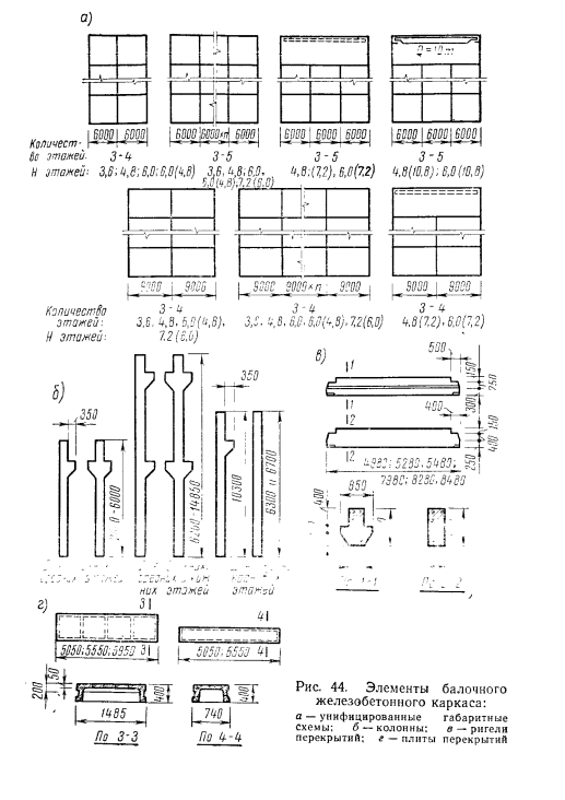
Fig. 44. Elements of the beam reinforced concrete frame:
a - unified dimensional schemes; b - columns: s - crossbars; g - floor slabs
Column sections - 400X400 and 400X600 mm. It is recommended to accept columns of constant cross-section for all floors (except the basement), as well as for the extreme and middle rows. The required bearing capacity of the columns is provided by changing the cross section of the reinforcement and concrete grade in accordance with the load.
To support and fasten the crossbars in the columns, consoles and embedded elements are provided. The columns are made of concrete grades 200-500 and reinforced with welded frames.
Depending on the type of support (on the top or on the shelf), the crossbars have a rectangular section and a rectangular one with shelves (Fig. 44, c).
In the first version, the cross-section of the crossbar is 300X800 mm, in the second, the width of the crossbar is 650 mm in the level of the shelves, and the height is 800 mm. The indicated cross-sections of the crossbars are the same for the grids of columns 6X 6 and 6X9 g. The length of the crossbars, depending on the span (6 or 9 m), the height of the cross-section of the columns (400 or 600 mm) and the gap between the crossbars and columns (usually 60 mm), is 4980, 5280, 5480, 7980, 8280 and 8480 mm.
For a grid of columns 6X6 m, the crossbars are designed from concrete of grades 200-300, and for a grid of columns of 6X9 m - from concrete of grades 300-400 with conventional or prestressed bar reinforcement.
The stiffness of the pairing of columns and crossbars is ensured by welding of supporting embedded elements and valve outlets, as well as by monolithic assemblies.
Floor slabs are accepted of two types: basic 1485 mm wide and additional 740 mm wide (Fig. 44, d). The height of the plates is 400 mm and the shelf thickness is 50 mm. The main plates are equipped with transverse ribs 200 mm high. For the option of bearing on the shelves of the crossbar, the plates have a length of 5550 and 5050 mm (plates adjacent to the ends and the temperature seams).
The length of the main plates for the support option on the top of the crossbar is 5950 mm (this option is used for heavy loads from large-sized sagging equipment).
Slabs laid along the axes of the middle rows of columns in the case of bearing on the top of the crossbars have cutouts at the ends to pass the columns. Additional plates laid on the outer rows of columns are the same for both types of ceilings.
The fastening of the plates to the crossbars is carried out by welding of embedded elements. The joints between the slabs are filled with concrete. For the manufacture of plates used concrete grades 200-400 and conventional or prestressed bar reinforcement.
The joints of the columns are placed above the ceiling by 600 mm if the plates are supported on the top of the crossbars, and by 1000 mm when the plates are supported on the shelves. Columns are joined by welding rods-overlays to the column heads formed by angles and plates. Install columns on centering gaskets. The gap between the ends of the columns is minted with a 300 grade hard mortar and, after installing the nets around the perimeter, are monolithic with concrete. Structural details of beam frames are shown in Fig. 45.
In the longitudinal direction of the building, in each row of columns in the middle of the temperature compartment, portal-type connections are made. Plates stacked between columns are used as spacers that transmit horizontal forces to a connected block. In these plates, embedded parts are provided for connecting to each other and for fixing the stop angles.
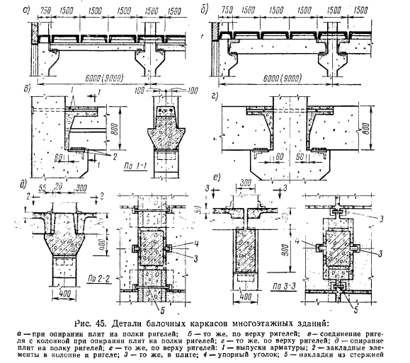
Fig. 45. Details of beam frames of multi-storey buildings:
a - when leaning the plates on the shelves of the crossbars; b - the same on the top of the crossbars; c — connection of the crossbar with the column when the plates are supported on the crossbars of the crossbars; e - the same on the top of the crossbars; d - supporting plates on a shelf of crossbars; e - the same, on top of the crossbars: 1 - rebar releases; 2 - embedded elements in the column and crossbar; 3 - the same in the stove; 4 - a persistent corner; 5 - lining of the rods

Additional rigidity of the building in the longitudinal direction can be provided by the device of longitudinal monolithic or prefabricated crossbars, laid instead of intercolumn slabs. To support the prefabricated longitudinal crossbars, steel tables are welded to the embedded parts of the columns at the level of the reinforced concrete consoles.
Structurally, the upper floors, with spans of 12, 18 and 24 m and equipped with cranes, do not differ from single-story buildings (the joint of the coating crossbar with columns is hinged).
The main technical and economic indicators of reinforced concrete elements of the beam frame of a multi-storey industrial building are given in table. 10.
The frameless frames of multi-storey buildings used for the installation of refrigerators, warehouses and industries with increased cleanliness requirements consist of the following five structural elements: foundations, columns, capitals, over-column and span plates. Prefabricated beamless frames compared with beam have approximately the same advantages and disadvantages as in monolithic versions.
The grid of columns in the frameless frames is 6x6 m. The floors usually have the same height of 3.6, 4.8 and 6 m. Elements of the frameless frame are shown in Fig. 46.

The columns are made with a cross section of 400X400 mm and a height of one floor. Columns are joined within the cavity of capitals, having the shape of a truncated pyramid with dimensions of 1750X1750 mm in plan. The columns of the first floor are based on foundations with glass-type pillars.
The popliteal plates are hollow with shelves for supporting span plates. Plate sizes: length 4800, width 2000 and thickness 300 mm. Span plates are also designed with 160 mm void thickness and 4250x4250 mm plan dimensions.
Capitals are attached to the columns by welding embedded elements. In both directions along the grid axes, capitals are laid on the capitals, fastened together by reinforcing bars, which are welded to the embedded elements (Fig. 46, f).
Overhead columns are connected to the capitals by welding. Span plates are supported on shelves of knee-high plates and fastened with them by welding of embedded elements. The upper part of the opening of the capitals and the space between the ends of the popliteal plates form glasses, where the columns of the next floor should be inserted. The remaining gaps are provided for filling with concrete on fine gravel, creating a hard joint.
Monolithic frame of the house
An example of a built monolithic frame
at home. Click on the photo to enlarge.
The construction of a private house based on a monolithic reinforced concrete frame is an almost ideal way to build a house. Reinforced concrete is the foundation, bearing columns and ceilings, and the walls are filled with masonry from blocks. The house is super durable; in fact, the same technology is used in the construction of modern skyscrapers. If the basement is planned in the house, then it is also made of reinforced concrete.
Building a house on the basis of a monolithic frame allows you to implement any planning ideas. You can make rooms of different sizes, heights and shapes. No need to snap to standard sizes concrete products (floor slabs). In too large rooms, supporting columns may appear on the "territory" of the room, this is inevitable.
A concrete frame is rarely built “manually” using unprofessional labor. Usually hire a normal construction company. Concrete, of course, is also used purchased. An electric vibrator is used to seal the concrete mixture after pouring.
In monolithic construction, concrete work can be performed at a time when all is poured concrete structure, or in stages, when concrete is poured in parts. It is clear that it is impossible to fill in the two-story frame of the house immediately as a whole. Therefore, concrete is poured in stages, as the previous part of the structure hardens: for example, the supporting columns on the second floor are poured after solidification between the first and second floors.
In this moment, the concept cold seam. The temperature has nothing to do with it, the cold seam is the border between the hardened concrete and the new batch of freshly poured concrete. Unfortunately, the cold seam is a weak spot in the concrete frame of the house, the adhesion of concrete is worse than in just a single-monolithic concrete.
But do not worry much about this issue. The appearance of cold joints is inevitable during the construction of a monolithic concrete frame of the house. Therefore, in order to improve the adhesion of the hardened concrete to the fresh one, the hardened concrete surface must be cleaned of dust, dirt, water, and also a cement film caused by the presence of salts.
Monolithic ceilings are made using horizontally exposed formwork (for example, from moisture-proof plywood) mounted on a variety of vertical metal jack stands. A reinforcing cage is knitted on the formwork, which is then poured with concrete. Supporting racks from under the ceiling are removed gradually, as the concrete sets.
Technological openings must be provided for in the ceiling: for a chimney, ventilation ducts, cables, sewer pipes, water and heating.
During the construction of load-bearing columns, unlike floors, concrete with higher mobility. The reason is the more abundant reinforcement of the columns, and concrete should occupy all available voids in volume. Mobility should not be achieved by excessive addition of water. Mobile concrete mixes are designated P1, P2, P3, P4, etc.
For monolithic columns, a special removable reusable formwork is usually used. There is no need to save here, otherwise the formwork can be torn apart by pressure from the inside. Normal construction companies have such a formwork, although its use is not cheap. People who fill the pillars themselves are forced to build very strong formwork for the pillars. Sometimes they build a “fixed formwork” of brick.
It is important to fill the entire column immediately to avoid the appearance of a cold seam in the column. It will appear only at the junction of the column and ceilings. The cold seam of the column should be horizontal.
Concrete work is very desirable at a positive temperature. There are additives in concrete for working with it in cold weather, and heating cables are also sometimes used. You can also build a tent from a plastic film over the construction site, but still, if possible, it is better to work with concrete in the warm season.
Wall filler in a monolithic frame does not have to be very strong, because reinforced concrete columns carry the load. The wall in this case only performs a limiting and heat-shielding function. In fact, you can fill the walls in a monolithic frame of the house with any material: warm ceramics, ordinary brick, blocks of cellular concrete (foam concrete, aerated concrete, etc.), wood concrete, etc.
Combinations of wall materials may be used. For example, facing brick outside, warm ceramics inside. Or the option is more expensive: facing brick + warm ceramic + inner layer of ordinary ordinary brick. The third inner layer of brick in this case is needed for comfortable use of the wall: it is convenient to ditch, drill, fasten, guaranteed nothing will fall out of the wall.
In houses based on a monolithic reinforced concrete frame, they can freeze monolithic floorsif they go outside and are not insulated. The thermal conductivity of reinforced concrete is approximately 1.69 W / (m · ° C), and this is not a weak bridge of cold inside the house. Therefore, all ends of the floors must be insulated.
Columns of a monolithic frame must be "put" to the inner side of the wall. The overlap goes beyond the columns and the wall material “bypasses” the column from the outside. Thus, the supporting columns are constantly in the heat zone and are not frozen in winter. This extends the life of the columns, although it is already very large.
The place in the outer wall where the support column is located can result in poor heat transfer resistance. Therefore, it may be necessary to use insulation on this wall section.
Although the column must be pressed to the inner side of the wall, it is not necessary to make the same even surface, the column must be insignificantly recessed inward. Due to this, if the walls are then gated, the strobes will not go along the column.
As one architect told me, there is a risk of moisture leaking from the concrete foundation from the concrete foundation. In this case, it is necessary to separate the frame from the foundation with waterproofing. Those. the frame will stand on the foundation on the waterproofing layer. The fact that there is no direct integral connection between the foundation and the frame is not worth fearing, gravity holds everything tight. The house is already super-strong.
Monolithic frame houses are well suited for earthquake-prone regions of Russia (Sochi, Yekaterinburg and other areas).
|
Igor (15.12.2015 11:36)
I do not understand those who are "steamed" about the "high cost and complexity" of the reinforced concrete frame. In aerated concrete - foam concrete walls, monolithic armpits are arranged under the ceiling without fail, you just need to add the columns and here it is - the frame (simplified) is almost ready .... And in this time you get a completely different quality house, which is not afraid of strong earthquakes, subsidence of the ground .... in case of severe fire - the frame will hold the floor (reinforced concrete) and allow safe evacuation .... Did anyone ever see the cracked walls of the aerated concrete house (sometimes you can stick a fist into them)? Such a house becomes unsuitable (unsafe) for living and the money spent on its construction can be considered lost in many ways, plus the cost of dismantling .... Yes, such cases are not widespread, but who will guarantee that the "savings" on the columns will not come around you .... The British are right in this regard (although I do not like them) - your house should be a fortress)))) |
The technology of construction based on a reinforced concrete frame is rarely used in low-rise construction. Most often, a reinforced concrete frame is used for the construction of high-rise buildings. In the case of low-rise construction, it is less economical in all respects than a house built using other frame technologies.
The main plus of the reinforced concrete frame is its high bearing capacity and durability. Also, with the help of reinforced concrete, spans of up to 6 meters can be made in impressive sizes, which again is not a necessity in low-rise construction.
However, reinforced concrete, thanks to a unique combination of steel reinforcement and concrete mix, is the main structural material of our time.
Concrete (GOST 7473-94) is an artificial stone material obtained as a result of the formation and hardening of a correctly selected concrete mixture consisting of cement, water, aggregates, and special additives. Before hardening, this mixture is called “concrete mixture”.
Steel reinforcement (GOST 10884-81) - material obtained from low alloy steel, hot rolled method. Most often in reinforced concrete structures, steel reinforcement is corrugated, for better adhesion to the concrete mixture.
- Reinforced concrete
These two materials were not accidentally combined into one. Concrete is a strong material that works excellent in compression, but crumbles and breaks when it works in bending, it is easy to observe on non-reinforced concrete screed. Steel also works very well in tension. And thanks to the good adhesion of these two materials, a fundamentally new and universal material appears - reinforced concrete.
Reinforced concrete is used in the construction of foundations, stiffness belts in buildings, steps and porches, etc.
When erecting a frame, reinforced concrete perceives the building loads best.
Reinforced concrete frames are divided into prefabricated and monolithic.
The precast concrete frame is a structural system of prefabricated columns of crossbars and beams at the factory, and delivered to the construction site for installation. At the same time, a certain freedom of the building’s shaping is limited, since the manufactured frame parts are accommodated and have certain standards.
A monolithic reinforced concrete frame is a structural system that is erected directly at the construction site, using a ready-mix of a certain brand. Such a frame is reinforced and cast in the given forms, according to the project.
- Monolithic reinforced concrete frame
Houses with a supporting frame made of reinforced concrete are quite popular. Such houses have undoubted advantages.
Architectural expressiveness. There are no design restrictions on the configuration of the building, the location of the columns. Buildings can take on any curved shape, have any number of storeys and workload.
The reinforced concrete monolithic frame of the building and the floor slab are created directly on the construction site using removable formwork. Concrete is poured into a pre-installed formwork, and the frame grows floor by floor. External walls can be any - brick, foam concrete, curtain. To the benefits monolithic construction refers to the ability to use a variety of architectural and planning solutions and fit the facilities being built into the landscape and existing buildings.
- Pros of a monolithic reinforced concrete frame
A monolithic reinforced concrete frame ensures the joint operation of all structural elements of the frame, which reduces the material consumption of the building. Rigid nodes between the supporting elements of the frame allow you to redistribute the forces in the columns, including the work of the beam and floor.
Any complex section (T-section, corner) of the main supporting element of the frame, columns, fits into the layout naturally and naturally.
Lightweight heat-efficient enclosing walls with high heat-shielding performance are used. For example, cellular concrete blocks in a single-layer version meet modern energy saving requirements.
The ability to ensure the joint work of all structural elements of the frame, which reduces the material consumption of the reinforced concrete building-2 and other Ryazan reinforced concrete plants sell products through our company rzn-gbi.ru. . Rigid nodes between the supporting elements of the frame allow you to redistribute the forces in the columns, including the work of the beam and floor.
Slight deformation of the frame in case of failure under the supporting column due to the joint work of the frame with the foundation plate. This can significantly reduce metal consumption during the construction of the building.
Another quality of frame-monolithic housing construction is its safety in extreme situations, the rigid concrete frame of the building will survive even with complete destruction of the walls, for example, with a gas explosion. Frame-monolithic housing can be of any category: from budget to luxury. The builders have no doubt that its consumer properties are higher than those of panel and brick.
- Improvement Options
Increasing the grade of concrete leads to a significant reduction in the consumption of expensive reinforcement and an overall decrease in the cost of construction. This is especially effective with three or more percent reinforcement of reinforced concrete, which means that optimization of monolithic frameworks is necessary for the cross section of reinforced concrete elements, the percentage of reinforcement, and the grade of concrete.
One way to increase the efficiency of monolithic frames can be to deepen the building's box into the ground on one or two floors with the implementation of the underground and basement in a monolithic version, including the outer walls. This will further increase the stiffness of the building and allow transferring loads from the building to more dense bedding.
- Minus
The cost of constructing a single-family 2-3-storey building using this technology in comparison with the technology of prefabricated floors using prefabricated floor panels remains significantly higher due to the use of expensive shuttering systems and expensive mechanization - concrete trucks, concrete pumps.
→ Building schemes
Reinforced concrete frames of buildings and structures
Frameworks of one-story buildings. Wireframe elements. The main elements of the reinforced concrete prefabricated frame of one-story industrial buildings: foundations, foundation beams (randbalks), columns, crane beams, load-bearing coating elements (trusses, beams) and communications.
All elements of prefabricated reinforced concrete frames are unified. The characteristics of each of them are given in special catalogs. To connect prefabricated reinforced concrete elements of the frame to each other, as well as for fixing walls, coatings and other elements of buildings, they have embedded steel parts.

Fig. 49. General view of the precast concrete frame: 1- column; 2 - crane beam; 3 - farm; 4- coating plates; 5 - steel frame lantern; communication
To sling the frame elements during their transportation, storage and installation during the manufacturing process, they lay the mounting (lifting) hinges of mild reinforcing steel (class A-1) or arrange special holes. Reinforced concrete elements are assembled into the frame by welding steel embedded parts. In fig. 49 shows a general view of a precast concrete frame of a single-story industrial building.
Foundations. Under the columns of the frame of the buildings, they stand separately reinforced concrete foundations step-shaped, having in the upper part a glass in which columns are installed (Fig. 50). For the construction of these foundations, see § 24. foundation beams. In industrial frame buildings with a column pitch of 6 and 12 m, foundation beams serve to support self-supporting walls on them and transfer loads from them to the foundations. Beams have a T-shaped (Fig. 51) or trapezoidal cross-section. The length of the main beams with a column pitch of 6 m is 4950 mm, with a pitch of 12 m - 10700 mm.
Fig. 50. Supporting columns on the foundation: 1 - column; 2 - foundation

Fig. 51. Foundation beam
Beams laid at the ends of the building and the expansion joints, where the column spacing is reduced, are 500 mm shorter than the main ones -4450 and 10,200 mm. The thickness of the beams for brick walls is 250, 380 and 510 mm, block -380 and 510 mm, panel -200, 240, 300 and 400 mm. The height of the foundation beams is 400 and 600 mm.
Beams 6 m long are made without prestress, 12 m long are pre-stressed.

Fig. 52. Supporting the foundation beam: 1 - foundation beam; 2 - concrete column; 3 - foundation
Under the outer walls, the beams are laid on the outside of the column, under the inner walls - between the columns on the longitudinal alignment axis. The beams rest directly on the steps of the foundations or on concrete columns (Fig. 52) laid out on these steps so that the upper face of the beams is located at -0.030, i.e. 30 mm below the level of the clean floor. The gaps between the ends of the beams, as well as between the ends of the beams and columns are filled with concrete grade 100.
On the leveled surface of the beams, horizontal waterproofing of the walls is arranged. In order to avoid deformation of the beams in heaving (clay) soils, as well as to protect the wall strip of the floor from freezing from below and from the sides of the foundation beams, slag bedding is made.
Base beams are made of concrete of grades 200-400, the working reinforcement of beams FB-steel aP class, FBN beams (strained foundation beams) - made of steel class A-Win.
The columns. In one-story industrial buildings, prefabricated reinforced concrete columns use continuous rectangular cross-sections (Fig. 53, a, b) and double-branch continuous (Fig. 53, c). In buildings equipped with bridge cranes, the columns have consoles for supporting crane beams on them, on which rails are laid to move the crane. Unified columns have a height that is a multiple of 600 mm. The design height of the column (N) is calculated from the level of the clean floor of the room, i.e., from the mark of 0, 000 to the top of the column, excluding its lower end, 900–1350 mm long, embedded in the foundation.

Fig. 53. Types of prefabricated reinforced concrete columns of one-story industrial buildings: a - for craneless buildings; b-crane rectangular section; c - two-branch crane for middle rows
The part of the column located above the consoles is called the over-crane, below - the crane. The supercrane part of the column supporting the coating elements is called the pericarp. In two-branch columns, the percolumn is made from one branch, as a result of which, ledges are created to support the crane beams. The upper end of the column has a steel embedded sheet with anchor bolts for fastening the bearing elements of the coating. Steel embedded parts are also provided in the places of installation of crane beams and ties and, in addition, in the lateral planes of the extreme columns (for fixing walls).
For the alignment of the columns during their installation, risks are provided in the form of vertical grooves of a triangular profile. They are applied on the four faces of the columns (top and bottom), as well as on the side faces of the console consoles.
The columns are made of concrete of grades 200, 300 and 400, and the working reinforcement is made of steel of A-Sh class.
The columns of the half-timbered house (auxiliary frame) are arranged on the front half-timbers and half-timbers of the longitudinal walls of one-story industrial buildings with wall lengths of 6 and 12 m.
The columns are designed for the load from the wind and the mass-panel walls. install columns on independent foundations. The outer edge of the columns is located in the plane of the inner surface of the walls.
Columns are made of concrete of grades 200-400, working fittings are made of steel of A-Sh class.
Fig. 54. Prefabricated reinforced concrete crane beams: a -T-section 6 m long; b-I-section 12 m long
Crane beams are used to move bridge cranes along them and are longitudinal connections between the columns of the frame. Beams are installed on reinforced concrete columns with a step of 6 and 12 m. Crane beams have a T-section or an I-section. Beams with a span of 6 m are made of T-shaped cross-section with a thickening of the wall on supports 800 and 1000 mm high (Fig. 54, a), and a span of 12 m - an I-section with a height of 1400 mm with a reinforced upper shelf (Riss 54, b). The upper shelves of the beams are mainly used for attaching crane rails to them. The beams are provided with embedded parts necessary for fastening the beams to the columns and rail tracks to the beams. All beams are pre-stressed.
Beams are made of concrete grade 300-500, the working reinforcement is made of high-strength wire VR-P, steel class A-Shv, etc.
Rafter beams. They are made single-pitched, gable and with parallel belts (Fig. 55).
Single-beam beams (Fig. 55, a) are used in coatings of one-story industrial buildings with a span of 6-12 m, with a column pitch of 6 m and an external drain. Gable beams (Fig. 55, b) are used in coatings of one-story industrial buildings with spans of 6-18 m, column spacing of 6 and 12 m with an external and internal drain. Beams with parallel belts (Fig. 55, c) are used in coatings of industrial buildings with a flat roof during spans of 12 and 18 steps of columns of 6 and 12 m. Rafter beams have a T-section or an I-section. In order to reduce the mass of beams and skip communications, holes of various shapes are arranged in their walls. Single and gable beams can be assembled from separate blocks with the subsequent tension of the reinforcement passed through them.
Beams are installed on reinforced concrete columns or on bearing walls with the device of reinforced concrete pillows, and beams with a span of 18 m also on the rafter beams. The columns of the coating beam are attached to the columns with anchor bolts released from the columns and passing through the supporting sheet welded to the embedded part of the beam. The supporting sheet of the beam is attached to the sheet embedded in the column.
In longitudinal longitudinal joints, one of the beams is equipped with a zink-roller support.
Beams are made of concrete of grades 300, 400 and 500, the working armature is made of high-strength wire of class Bp-P or rods of steel of class A-IV and A-Shv.

Fig. 55. Reinforced concrete beams: a - single-pitched; b - gable; in - with parallel belts
Rafter trusses - structures consisting of separate interconnected rods forming a frame.
The truss rods located along its upper contour make up the upper belt, and the lower belt along the lower contour. The vertical rods of the farm are called racks, inclined - splits. Racks and braces located between the upper and lower belts form the farm lattice, and the points (places) at which the ends of the racks and braces converge are the nodes of the farm. The area between two adjacent nodes is called a panel.
Depending on the shape of the upper zone, the farms are divided into segmented ones, with parallel belts, etc. (Fig. 56). Reinforced Concrete Farm may be integral or composite. Compound farms are made of two semi-farms or several blocks.
Fig. 56. Reinforced concrete prestressed Truss trusses: a - segment truss; b - farm with parallel belts
They are used in pitched and flat coatings of one-story industrial buildings with a span of 18 m or more. Install roof trusses reinforced concrete columns or trusses. For fastening of trusses to columns (truss trusses), as well as trusses of coating slabs, lantern frames, ties, corresponding steel embedded parts are provided in them.
Farms are performed with prestressing the lower zone and the extended braces (in farms with parallel belts).
Farm is made of concrete grades 300-500, working fittings. - from high-strength wire VR-N and rods from steel of class A-IV
and etc.
Truss trusses and beams are used in coatings of single-story multi-span industrial buildings along with truss trusses and beams (Fig. 57),
Truss trusses and beams are used in the middle rows of buildings to support trusses or roof beams in cases where their step is 6 m and the column pitch of the middle rows is 12 m.
The trusses (beams) are installed along the building directly on the columns with which they are fastened by welding embedded parts. All trusses (beams) have the same span of 12 m, except for trusses installed at the ends of the building and at transverse temperature joints, the span of which is 11.5 m (in accordance with the location of the columns). At the ends and in the middle (in the lower node) of the truss trusses (beams), platforms are provided for supporting the truss trusses (beams). There are embedded sheets in the sites with anchor bolts welded to them.
Farms (beams) are made with prestressing of the lower belt of concrete of grades 400 and 500. The main (prestressed) reinforcement is made of high-strength wire of class Vr-11 and steel of class A-1U, etc.
Communication. The stiffness of the precast concrete frame in the transverse direction (across the spans) is provided by the stiffness of the columns themselves and their fastening in the foundations. In the longitudinal direction (along the spans) in buildings with and without bridge cranes at a height of more than 9.6 m, the rigidity of the frame is provided by the mouth, a novelty of longitudinal vertical steel ties (Fig. 58), which are located in each longitudinal row of columns at the middle of each temperature block. They are made of rolling profiles and welded to special embedded parts of the columns.

Fig. 57. Sub-rafter reinforced concrete prestressed structures: a - beam; b - farm; in-detail resting support trusses on the truss truss; 1 - truss truss; 2 - rafter trusses; 3 - coating plates; 4- embedded parts for mounting farms; 5 - the same for mounting plates

Fig. 58. Vertical connections between columns: a - cross; b - portal; 1 - reinforced concrete columns; 2 - crane beams; 3 - beams (or trusses) of the coating; 4 - vertical ties
In addition to vertical connections between columns, horizontal and vertical connections between trusses (beams) of the coating are also established. Horizontal, ontal connections are established in horizontal planes, i.e. in the planes of the upper and lower zones of the trusses, vertical - in the vertical planes between the trusses.
Frameworks of multi-storey buildings are of frame, link and frame-link type. For buildings from prefabricated reinforced concrete elements, frames of a frame-link system are more often used (Fig. 59).
Fig. 59. A multi-storey building with beam ceilings of a frame-coupled system: 1 - self-supporting wall; 2 - a crossbar with regiments; 3 - ribbed plates; 4 - column console

Fig. 60. Columns of multi-storey industrial buildings
The main elements of such a frame are columns, girders, floor slabs, communications.
Columns (Fig. 60) of the skeleton of multi-storey industrial buildings usually have a continuous rectangular section 400 × 400 or 400 × 600 mm in size, one or two floors high and are cantilevered. In the building plan, the columns have a grid of 6 × 6 or 9 × 6 m.
The columns of the lower floor rest on the foundations of the glass type. The columns of the upper floors are interconnected by welding embedded steel parts. The ends of the columns are equipped with steel heads (welded from corners and strips), to vertical walls which are welded to the ends of the working reinforcement of the columns. The joint is carried out by welding to the same ends of the short butt rods.
In the frameworks of multi-storey buildings, the junction of columns for ease of installation is usually provided at a height of 0.6 m from the floor level.
The columns are made of concrete of grades 200-500, the working arm-TURU is made of A-Sh class steel.
Crossbars (Fig. 61) are used as part of prefabricated reinforced concrete floors in multi-storey buildings. Crossbars are made with shelves for supporting plates and of rectangular cross section without c0ch locks 6 and 9 m long, 800 mm high and 300 mm wide.
Crossbars with a span of 6 m are made without prestressing. niya, and with a span of 9 m - with a preliminary voltage of two or three rods of the lower working reinforcement. For hanging comm. In the crossbars, through holes with a diameter of 50 mm are provided. When mounting the frame, these holes are used to lift the crossbars.
Fig. 61. Rzhel

Fig. 62. Floor slabs
At the ends of the crossbars in the upper part there are recesses in which the outlets of the upper supporting reinforcement of the crossbar are located, which are joined with the outlets of the reinforcement of the columns.
The crossbars are installed on the console of reinforced concrete columns and connected to the columns by welding fittings and embedded parts, followed by monolithic. They are made of concrete of grades 200-400, reinforcement is made of steel of A-Sh class (without prestressing) and A-Shv - for prestressed.
Floor slabs (Fig. 62) are used as part of prefabricated reinforced concrete floors buildings. In multi-storey buildings, two types of floor slabs are used. Plates of the 1st type are made with a width of 1,500 and 750 and a length of 5550 and 5050, plates of the 2nd type are made with a width of 1500 and a length of 5950 mm. Slabs with a nominal width of 750 mm are stacked at the longitudinal walls of the building.
All plates perform a U-shaped section 400 mm high. At the ends of the slabs there are blind transverse ribs of the same height (slabs of the 1st type) and a height of 150 mm (slabs of the 2nd type). In addition, there are three intermediate transverse ribs 200 mm high on arrival. Plate shelf thickness 50 mm. Holes with a diameter of 35 mm (after 1 m) are located in the longitudinal ribs for suspension of electrical wiring and other loads weighing up to 300 kg per one hole.
Intercolumn slabs (type 2), laid along the longitudinal alignment axes, the so-called spacer or communication slabs, have cutouts in the shelves in the places adjacent to the columns. Plates are made without prestressing or with prestressing of the working fittings. The longitudinal and transverse edges of the plates are reinforced with flat welded frames, the shelf with a welded mesh. The main reinforcement is rod.
Slabs of the 1st type are laid on the shelves of reinforced concrete crossbars (1st type), slabs of the 2nd type are placed on top of reinforced concrete crossbars of rectangular cross-section (2nd type).
Slabs are made of concrete of grades 200-300 (slabs of the 1st type) 300-400 (slabs of the 2nd type), and the main working armature is made of steel class AI, A-W and A-W c.
Communication. In prefabricated reinforced concrete frames of a frame-and-bond system of multi-storey buildings, columns and crossbars form a series of transverse frames providing spatial rigidity of the frame in the transverse direction. The rigidity of the crossbar and column pairing units is achieved by welding embedded parts of the regions and consoles of the columns, as well as by welding the outlets of the upper reinforcement of the crossbars with rods passed through the body of the column. The gaps between the columns and the ends of the crossbars are filled with concrete.
To ensure spatial rigidity of the building frame in the longitudinal direction on all floors in the middle of each temperature block between the columns of the longitudinal rows, vertical steel ties of the cross or portal type are welded to the embedded parts of the columns (see Fig. 58).
In multi-storey buildings, the spatial stiffness of the building as a whole is also ensured by the design of so-called walls (diaphragms) and stiffness cores in them. The stiffening walls are made of precast or monolithic reinforced concrete. ” As precast concrete use separate wall panels that are installed between the columns of the building frame. The panels are fastened to the columns and to each other (along the height of the floors) by electric welding of embedded steel parts in panels and columns. The number and location of the stiffness walls in each building are determined by calculation and are indicated in the design.
Spatial stiffness cores, as a rule, are arranged with monolithic reinforced concrete, with a wall thickness of 20-40 cm or more, in sliding or interchangeable formwork. Within the core are usually located staircase elevator nodes, ventilation shafts, garbage chutes and other communications. The stiffness cores provide (due to the advantageous static work) high stiffness of the building with a minimum consumption of concrete and steel compared to flat systems of bonded diaphragms. In addition, spatial stiffness cores work effectively on the perception of torques arising under the action of asymmetric horizontal (wind) loads.
Expansion joints. In the carcasses of buildings of considerable length, expansion (temperature) seams are arranged that divide the carcass and all the structures resting on it into separate sections - blocks (Fig. 63). Distinguish between transverse and longitudinal seams.
Transverse temperature seams are made of double columns and\u003e as a rule, without insertion, i.e., without doubling the transverse alignment axes. The axis of the temperature joint is aligned with the transverse broken axis, and the geometric axes of the columns (as well as the supporting floor structures supported on them) are shifted from the axis of the temperature of the joint by 500 mm. In this case, adjacent to the seams sections at. shortened slabs are changed, and special reinforced concrete elements are used to fill the gap between the twin bolts.

Fig. 63. Expansion joints in frame buildings; a - diagram of the temperature transverse seam (without insert); b, c - the same, longitudinal seams (with an insert); g - transverse seam in the coating; 1 - axis of the row; 2 - axis of the column; 3 - steel table; 4 ~ reinforced concrete insert; 5 - reinforced concrete slab coating; 6, 7 - compensators; 8 - brick wall; 9 - board; 10 - apron
Longitudinal expansion joints in buildings with a reinforced concrete frame are made of two rows of columns with an insert between alignment axes of sizes 500, 1000 and 1500 mm, and in buildings with a steel or mixed frame, from one row of columns.
If in the longitudinal temperature joint in the coating there are sub-rafter structures, then columns of 250 mm are required for their placement. Sometimes the temperature seam is combined with sedimentary. In such cases, a temperature-sedimentary seam is also arranged in the foundations of paired columns. Distances between temperature and temperature-sedimentary joints for various buildings and structures are given in the relevant design standards.
Frameworks of structures. Silos. Silo casings serve for storage of bulk materials (grain, cement). Silo frames are constructed from prefabricated reinforced concrete structures or from monolithic reinforced concrete. However, the construction of monolithic silos has a number of significant drawbacks: the impossibility of applying prestressing reinforcement, heat treatment, etc. the use of monolithic reinforced concrete complicates the production of work in winter conditions.

Fig. 64. Silo housing made of precast concrete (cross section): 1 - large panels; 2 - frame; 3 - plate; 4 - rings; 5 - slag concrete; 6 - columns; 7 - monolithic reinforced concrete slab; 8 - wall blocks; 9 - pilasters in extreme blocks
In recent years, prefabricated reinforced concrete silos have been built to store grain and cement, the construction of which has largely eliminated the above disadvantages inherent in monolithic silos. In a silo housing for storing grain, consisting of two blocks of 24 cans with a total capacity of 32 thousand tons, of monolithic reinforced concrete only the foundation slab is made, the rest of the constructions are made of precast concrete (Fig. 64). Silo banks with a height of about 30 m, consist of reinforced concrete rings with a height of 1480 mm, reinforced with welded wire mesh; the inner diameter of the rings is 5.7 m, the wall thickness is 120 mm, and the mass is 8.1 tons.
Silos for storing cement with a height of about 25 m are mounted from rings with a height of 1490 mm, having an inner diameter of 10 m, walls with a thickness of 200 mm and a mass of 24 tons. For joining the rings, trapezoidal grooves are provided on their upper ends, and ridges on the lower ends.
The connection of the rings in banks is made in two ways. The first option is that the rings rest on each other dry in two circular areas. In the second embodiment, the joint of the rings is performed with a gap of about 20 mm, which is filled with a solution during installation. On the circumference of the rings, in their grooves and flanges, in advance (during manufacture), three steel support tiles are closed up, with which the rings are supported on each other through centering gaskets during installation. The first option to connect the rings is much simpler than the second, but does not always ensure the exact horizontality of the joints of the rings; with it, local open gaps at the joints and violation of the verticality of the walls of the cans are possible.

Fig. 65. Fan cooling tower
The connection of the cans with each other along the generators is carried out by reinforcing the joint with vertical spatial frames and grids, which also go into the horizontal joints between the rings. The joint is concreted in a metal formwork attached to the outlets of the reinforcement.
Cooling Towers In the USSR, multi-sectional fan cooling towers from prefabricated reinforced concrete unified elements have been developed and are being built (Fig. 65). The ground frame of such a tower consists of columns with a section of 200 × 200 mm installed at a distance of 4 m from one another and connected by transverse and longitudinal two-branch beams with a length of 8 m with a total section of 500 X 200 mm. Each beam has three slots for connecting to columns. To install sprinkler blocks in the three lower tiers, intermediate beams are laid on the beams of the main frame. The top of the tower consists of reinforced concrete short racks located along the outer perimeter of the sections of the tower, beams and roofing slabs.
The construction of houses with reinforced concrete frame is as popular as the construction of other types monolithic houses. The frame-monolithic house is based on a supporting frame, consisting of columns and ceilings with walls made of small-piece materials - brick or blocks.
Material characteristic
A monolithic reinforced concrete frame is constructed of concrete, a brand of strength, frost resistance and density of which is determined by the project. Columns and ceilings are reinforced with individual rods connected by structural reinforcement and nets. The diameters of individual rods, reinforcement in the grids and their pitch are also accepted in the design project.
Production technology
To install the reinforced concrete frame of the building on the prepared foundation, the formwork for erecting columns is first installed and reinforced. Concrete is poured at the same time using a concrete pump, the mixture must be vibrated. After the concrete has set, the formwork of the columns is removed and a horizontal formwork for the floors is installed, which is also reinforced with nets and poured with concrete. In the case when the house has several floors, the whole procedure is repeated. After the finished reinforced concrete frame of the building gains the necessary strength, the external and internal walls are laid out of brick or blocks. The house is revetted with facade materials from the outside, it is finished inside.
Advantages and disadvantages
The construction of monolithic-frame houses has the following advantages:
- strength, stability and durability. A monolithic house with a frame is not afraid of possible soil deformations, since the whole structure is reliably connected into a single rigid spatial structure;
- environmental friendliness - all elements of the building are made of environmentally friendly materials;
- fire safety;
- the possibility of flexible planning and redevelopment in the future.


