Outdoor switchgear equipment working principle. Traditional switchgears. Closed switchgears and substations
And means of accounting and measurement.
Encyclopedic YouTube
Classification
By location
- Open switchgears (switchgear) are switchgears in which power conductors are located in the open air without protection from environmental influences. Typically, in the form of outdoor switchgear, switchgears for voltages from 27.5 kB are made.
- Closed switchgear (switchgear) - switchgear, the equipment of which is installed in closed rooms, or is protected from contact with the environment by special enclosures (including in outdoor cabinets KRUN). Typically, such switchgears are used for voltages up to 35 kV. In some cases, it is necessary to use switchgear at higher voltages (equipment commercially available for voltages up to 800 kV). The use of high voltage switchgear is justified: in areas with an aggressive environment (sea air, increased dust), a cold climate, during construction in cramped conditions, in urban environments to reduce noise and architectural aesthetics.
For partitioning
RU with one section of busbars (without sectioning)
The advantages of such switchgear include simplicity and low cost.
The main disadvantages include inconvenience in operation, because of which such a system has not received widespread use:
- Preventive repair of any element of the switchgear must be accompanied by a shutdown of the entire switchgear - and thus deprivation of all electricity consumers that are powered by the switchgear.
- An accident on busbars also disables all switchgear.
RU with two or more sections
Such switchgears are made in the form of several sections, each of which has its own power supply and its own load, interconnected by sectional switches. At stations, the sectional switch is usually turned on, due to the need for parallel operation of the generators. In case of damage on one of the sections, the sectional switch is turned off, cutting off the damaged section from the switchgear. In the event of an accident at the sectional switch itself, both sections fail, but the likelihood of such damage is relatively small. On low-voltage switchgear (6-10 kV), the sectional switch is usually left open, so that the interconnected sections operate independently of each other. If for any reason the power of one of the sections is lost, the ABP device will work, which will turn off the input switch of the section and turn on the section switch. Consumers with a disconnected section will receive electricity from the adjacent section through a sectional switch. A similar system is used in switchgear of 6 - 35 kV substations and 6 - 10 kV stations of the type of CHP.
Switchgear with busbar section and bypass
Simple sectioning does not solve the problem of the scheduled repair of individual section switches. If it is necessary to repair or replace the switch of any outgoing connection, it is necessary to turn off the entire section, which in some cases is unacceptable. A workaround is used to solve the problem. The bypass device is one or two bypass switches in two sections, bypass disconnectors and a bypass bus system. The bypass bus system is connected via bypass disconnectors to the disconnect switches of the connection switches on the opposite side from the main bus system. In the case when it is necessary to carry out a scheduled repair or replacement of any circuit breaker, turn on the bypass switch, turn on the bypass switch corresponding to the desired switch, then the repaired switch together with its disconnectors is turned off. The power supply to the outgoing connection is now via the bypass switch. Similar systems have spread in switchgear at a voltage of 110-220 kV.
By the number of busbar systems
With one busbar system
These RUs are described above.
With two busbar systems
Such a switchgear is similar in design to a switchgear with sectionalization of busbars and a bypass device, but, in contrast to it, the bypass bus system is used as a working one, the load on the system is distributed between both bus systems. This is done to increase the reliability of power supply. Lack of power on one of the bus systems is allowed only temporarily, while repairs are being carried out on this bus system.
The advantages of this system include:
- Possibility of scheduled repair of any tire system, without decommissioning the entire switchgear.
- The possibility of dividing the system into two parts, to increase the reliability of power supply.
- Possibility to limit short circuit current
The main disadvantages include:
- Circuit complexity
- Increased likelihood of damage to busbars due to frequent switching of disconnectors.
The system is most widely used in switchgear at a voltage of 110-220 kV
According to the structure of the scheme
Radial type
The following characteristics are inherent in this type:
- Sources of energy and connections converge on the busbars, so an accident on the tires leads to the conclusion of the entire section (or the entire system)
- The decommissioning of one switch from the connection leads to the disconnection of the corresponding connection.
- Disconnectors, in addition to their main function (isolation of disconnected elements from the switchgear), are involved in circuit changes (for example, the introduction of bypass switches), which reduces the reliability of the system.
Ring type
The ring type of the circuit is distinguished by the following features:
- The circuit is made in the form of a ring with branches of connections and power supplies
- Each connection is disconnected by two or three switches.
- Opening one switch does not affect the power supply
- In case of damage (short circuit or outages) on the switchgear, only a small part of the system fails.
- Disconnectors perform only the main function - isolate the decommissioned element.
- Ring circuits are more convenient than radial ones in terms of system development and adding new elements to the system.
Outdoor switchgear
Design Features
An open switchgear (switchgear) is a switchgear whose equipment is located outdoors. All elements of outdoor switchgear are placed on concrete or metal substrates. The distances between the elements are selected according to the PUE. At a voltage of 110 kV and higher, oil receivers are created under the devices that use oil for operation (oil transformers, switches, reactors) - recesses filled with gravel. This measure is aimed at reducing the likelihood of a fire and reducing damage during an accident on such devices.
The outdoor busbars of the outdoor switchgear can be made either in the form of rigid pipes or in the form of flexible wires. Rigid pipes are mounted on racks using support insulators, while flexible pipes are suspended on portals using suspension insulators.
The territory in which the outdoor switchgear is located is fenced without fail.
Benefits
- Outdoor switchgear allows you to use arbitrarily large electrical devices, which, in fact, is due to their use at high voltage classes.
- The manufacture of outdoor switchgear does not require additional costs for the construction of premises.
- Outdoor switchgear is more convenient than indoor switchgear in terms of expansion and modernization
- Possible visual observation of all devices outdoor switchgear
disadvantages
- The operation of outdoor switchgear is difficult in adverse climatic conditions, in addition, the environment has a stronger effect on the elements of the outdoor switchgear, which leads to their early wear.
- Outdoor switchgear takes up much more space than indoor switchgear.
Closed Switchgear
In some cases, the same equipment is used for the indoor switchgear as for the outdoor switchgear, but with indoor placement. Typical voltage class: 35 ... 110 kV, less often 220 kV. This type of switchgear has few advantages compared to switchgear, so it is rarely used. More practical is the use of special equipment for indoor switchgear.
Complete switchgear (switchgear)
A switchgear assembled from typical unified blocks (so-called cells) of a high degree of readiness, assembled at the factory, is called a complete switchgear. At voltages up to 35 kV, the cells are manufactured in the form of cabinets connected by side walls in a common row. In such cabinets, elements with voltages up to 1 kV (metering, relay protection, automation and control circuits) are made with wires in solid insulation, and elements from 1 to 35 kV with air-insulated conductors (busbars with insulators).
For voltages above 35 kV, air insulation is not applicable, therefore, elements under high voltage are placed in sealed chambers. Outdated technology uses SF6 gas, while in Europe SF6 gas is gradually being replaced by vacuum interrupters with a relatively simple design. Cells with gas-insulated chambers have a complex structure that looks similar to a network of pipelines. Gas-insulated switchgear is abbreviated as switchgear, the abbreviations for switchgear with vacuum interrupter chambers have not yet been put into circulation.
Vacuum devices have a higher switching resource and are suitable for frequent switching, while gas-insulated units are used for operation in circuits of electric motors with limited power. At the same time, the accumulated operating statistics demonstrate the indisputable advantages of vacuum circuit breakers - the case of blocking control circuits of 59 SF6 tank circuit breakers of 110-500 kV produced by a number of European companies at an ambient temperature of -41 ° C in the Tyumen region in 2006 due to imperfect design, insufficient power, low reliability of the heating devices of the tanks and the shortcomings of the control system of pressure (density) of SF6. Despite the advantages of the new technology in the Russian energy sector, the share of vacuum circuit breakers is only 10-15%. . In 2007 in Russian Federation at NPP Kontakt JSC as part of the program technical re-equipment distribution grid complex started the development of vacuum circuit breakers 110–220kV
Application area
Complete switchgears can be used both for indoor and outdoor installation (in this case they are called KRUN). Switchgear is widely used in cases where compact distribution of the switchgear is required. In particular, switchgear is used at power plants, urban substations, for powering oil industry facilities (oil pipelines
- Low-voltage equipment is located in the relay compartment (3): relay protection and automation equipment, switches, circuit breakers. On the door of the relay compartment, as a rule, there are light-signal fittings, power metering and measuring devices, and cell control elements.
- In the compartment of the switch (4) there is a power switch or other high-voltage equipment (disconnecting contacts, fuses, VT). Most often in switchgear, this equipment is placed on a withdrawable or retractable element.
- In the busbar compartment (6) there are power buses (8) connecting the cabinets of the switchgear section.
- The input compartment (5) is used to accommodate cable cutting, current measuring transformers (7), voltage transformers, surge arresters.
Factories manufacture cells for complete switchgears for various purposes, which are divided into:
- for functional purposes - introductory, linear, auxiliary needs, voltage transformers, etc .;
- by type of input and output lines - for air inlet or outlet, for cable inlet or outlet;
- as intended - general purpose, for powering excavators, for electric vehicles, etc.
- by type - for single use and for integration into the switchgear assembly;
- by type of installation - for indoor and outdoor use (KRUN);
- by value of rated current;
- on the design of the visible gap (for the safety of work on the lines) - with disconnectors and a switching device in a retractable design (on a trolley).
To distinguish cells of the same type and brand, but having different functional purposes (sometimes different types of input or output), the manufacturer assigns them catalog numbers.
Electric machines and transformers installed in power plants and substations, lines of electrical networks need to be controlled and protected from damage and abnormal conditions. For this, switching devices, measuring transformers, current-limiting reactors, arresters and other electrical equipment of primary (power) circuits are needed. Also needed are control, monitoring, measuring, relay protection and automation devices that form the secondary circuits of the electrical installation. The listed elements of the electrical equipment of the primary and secondary circuits together with auxiliary devices and the construction part form the switchgear (RU) of the station or substation.
Distinguish between indoor and outdoor switchgear with electrical equipment located in buildings and outside buildings. In the latter case, it must be adapted to operate at air temperatures that vary over a wide range, in rain and snow, with wind and ice.
At the stations there are switchgears of several stages of rated voltage, connected through power transformers or autotransformers. Each RU. as a rule, it contains busbars (three-phase conductor system) and a number of busbar connections or branches with associated equipment. Depending on the purpose of the electrical installation, the rated voltage, the number and power of the switchgear connections, it can be performed with one or two busbar systems; with one or two switches in each connection and other features that determine the operational properties of the switchgear and its cost.
A visual representation of the switchgear or the installation as a whole is given by the electrical circuit - a graphic representation of the electrical installation using conventional symbols in accordance with the actual composition of electrical equipment and the order of electrical connections. The degree of detail of the scheme may vary. In the future, single-line circuits are widely used, in which equipment elements and conductors of one phase are indicated. Devices, control devices and relay protection, and in some cases measuring transformers in such schemes are omitted.
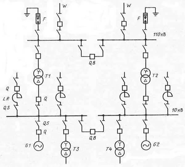
Fig. 1. Single-line scheme of a medium-sized power plant with switchgear of 10 and 110 kV:
G is the generator; T - transformer; Q - switch;
QB - sectional switch; QS - disconnector;
LR - current limiting reactor; F - arrester;
W - power line
As an example, Fig. 1 shows a single-line diagram of a medium power station with switchgear of 10 and 110 kV. In order not to complicate the circuit, single busbar systems are conventionally adopted for both switchgear. To the 10 kV busbars, two generators G1 and G2, two main transformers T1 and T2, two step-down auxiliary transformers of stations T3 and T4 and four lines of the local distribution network with current-limiting reactors LR are connected. Two main transformers and two W lines connecting the station to the system are connected to the 110 kV busbars.
Closed Switchgear
Closed switchgears and substations.
Closed switchgear most often build up to 10 kV inclusive. If it is difficult to obtain the site necessary for the placement of outdoor switchgear, when located at enterprises in cramped conditions, in areas with polluted air that destructively affect open current-carrying parts and reduce the insulating properties of porcelain, as well as in northern areas with very low temperatures and heavy snowfalls, they build ZRU 35 and 110 kV. At the same time, 110 kV indoor switchgear is constructed using equipment designed for outdoor switchgear.
Closed switchgears are placed in one-, two- or three-story buildings from standardized teams reinforced concrete structures. Closed switchgear 6 and 10 kV and substations are placed in built-in, attached or detached buildings made of brick or precast concreteconstructed on the foundations of reinforced concrete blocks.
Closed switchgear 35 and 110 kV are placed in separate buildings made of precast concrete. The dimensions of the rooms depend on the type of electrical equipment used, the main circuit diagram, the filling pattern and the acceptable dimensions of the width of the corridors and passages in the switchgear, transformer chambers and switchboard rooms (Table 4). When assembling switchgear and substations, the existing building standards and the dimensions of typical elements of precast concrete are taken into account: reinforced concrete slabs, beams, roofing and floor floors.
When designing the indoor switchgear and substations, the requirements of the EMP are taken into account, the main of which are given below. RU premises are separated from other rooms by walls or partitions and ceilings. Switchgears above 1 and up to 1 kV, as a rule, are placed separately. Depending on the length in the room of the switchgear, one (with a length of up to 7 m) or two exits (with a length of more than 7 and up to 60 m) arranged at its ends (it is allowed to place the exits from the switchgear at a distance of up to 7 m from its ends).
Doors from switchgear open in the direction of other rooms, outward or towards switchgear with lower voltage, and have self-locking locks that can be opened from the inside of the room without a key. The installation of thresholds in the doors is not allowed.
The most common installation of modern indoor switchgear and substations of 6 and 10 kV received complete devices. Complete switchgears are assembled from prefabricated one-way service chambers (KSO-272 and KSO-366) or cabinets KRU-2-6, KRU-2-10, KR-Yu / 500, K-XII, K-XV. They are delivered according to custom designs with the main circuit devices installed in the chambers and cabinets, with protection, measuring, metering and alarm devices, with a full bus and secondary circuit wiring within the chambers.
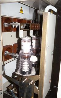
Outdoor switchgear
Oil switch in outdoor switchgear
Design Features
An open switchgear (switchgear) is a switchgear whose equipment is located outdoors. All elements of outdoor switchgear are placed on concrete or metal substrates. The distances between the elements are selected according to the PUE. At a voltage of 110 kV and above, oil receivers are created under the devices that use oil for operation (oil transformers, switches, reactors) - recesses filled with gravel. This measure is aimed at reducing the likelihood of a fire and reducing damage during an accident on such devices.
The outdoor busbars of the outdoor switchgear can be made either in the form of rigid pipes or in the form of flexible wires. Rigid pipes are mounted on racks using support insulators, while flexible pipes are suspended on portals using suspension insulators.
The territory in which the outdoor switchgear is located is fenced without fail.
Benefits
§ Outdoor switchgear allows the use of arbitrarily large electrical devices, which, in fact, determines their use at high voltage classes.
§ The manufacture of outdoor switchgear does not require additional costs for the construction of premises.
§ Outdoor switchgear is more convenient than indoor switchgear in terms of expansion and modernization
§ Possible visual observation of all devices outdoor switchgear
disadvantages
§ Operation of outdoor switchgear is difficult in adverse weather conditionsIn addition, the environment has a stronger effect on the outdoor switchgear elements, which leads to their early wear.
§ Outdoor switchgear takes up much more space than indoor switchgear.
A complete switchgear (switchgear) is a switchgear assembled from standard unified units (so-called cells) of a high degree of readiness, assembled in the factory. At voltages up to 35 kV, the cells are manufactured in the form of cabinets connected by side walls in a common row. In such cabinets, elements with a voltage of up to 1 kV are made with wires in solid insulation, and elements from 1 to 35 kV are made with conductors with air insulation.
For voltages above 35 kV, air insulation is not applicable, therefore, elements under high voltage are placed in sealed chambers filled with SF6 gas. Cells with gas-insulated chambers have a complex structure that looks similar to a network of pipelines. Gas-insulated switchgear is abbreviated for GIS.
Application area
Complete switchgears can be used both for indoor and outdoor installation (in this case they are called KRUN). Switchgear is widely used in cases where compact distribution of the switchgear is required. In particular, switchgear is used at power plants, urban substations, for powering oil industry facilities (oil pipelines, drilling rigs), and in ship power schemes.
The switchgear, in which all the devices are located in one compartment, is called the one-way service team (CSR) camera. As a rule, CSR is really one-way service, most often it has open busbars, there is no back wall.
Switchgear device 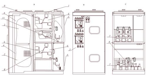
As a rule, the switchgear cabinet is divided into 4 main compartments: 3 high-voltage - cable compartment (input or line), circuit breaker compartment and busbar compartment, and 1 low-voltage relay cabinet.
§ In the relay compartment (3) there is low-voltage equipment: relay protection and automation equipment, switches, circuit breakers. On the door of the relay compartment, as a rule, there are light-signal fittings, power metering and measuring devices, and cell control elements.
§ In the compartment of the switch (4) there is a power switch or other high-voltage equipment (disconnecting contacts, fuses, VT). Most often in switchgear, this equipment is placed on a withdrawable or retractable element.
§ In the busbar compartment (6) there are power buses (8) connecting the cabinets of the switchgear section.
§ The input compartment (5) is used to accommodate cable cutting, measuring current transformers (7), voltage transformers, surge arresters.
RU up to 1000V.
The main type of switchgear up to 1000 V are switchboards. With their help, they supply external loads and the auxiliary needs of substations. Switchboards are diverse in schemes and in the apparatus and devices installed in them. The panels are completed from panels or cabinets interconnected in quantities and combinations corresponding to the design scheme and the construction part of the switchboard room. The panel (or cabinet) is a completely finished element of the shield, and the shield as a whole is a complete electrical device.
The panel is a metal structure (frame with front panel), on which apparatuses and devices for switching, measuring and protection are installed. The panel panels are connected by busbars and secondary circuit wiring, to which the equipment mounted on the panels is connected. They are divided into introductory, linear and sectional, depending on the purpose of the devices installed on them, as well as end ones, the purpose of which is the protective and decorative closing of the sides of the outer panels of the shield. Panels of all series are based on a single frame made of bent steel sheets 2-3 mm thick with parts from steel bent profiles for fixtures and the same design: two front racks, upper facade sheet for measuring instruments, doors for servicing devices installed on the frame inside, two rear pillars, transverse and longitudinal ties. The handles of the drives of automatic machines and knife switches through rectangular openings are displayed on the facade of the panel.
Installation of panels begins with the marking of the installation site of the foundation frame, which should be installed at the first stage of installation work. The passages between the wall and the shield, the symmetrical arrangement of the longitudinal and transverse axes of the shield to the shield room, the interface with cable channels and openings, taking into account the mark of the clean floor, are checked.
The panels are installed after construction and finishing work on the foundation frame, verified in horizontal and vertical planes and temporarily fixed. After installation, connection of blocks or panels to each other and alignment, the shield is finally fixed with bolts or welding. The assembly of the busbars and the installation of devices received in a separate package are carried out.
A complete switchgear (switchgear) is a device consisting of cabinets in which switching devices, devices, protections, automation and telemechanics, measuring instruments and auxiliary devices are delivered, delivered to the installation site in a fully assembled and fully assembled form.
Switchgear is designed to receive and distribute electric power of alternating three-phase current of industrial frequency 50 Hz, voltage of 6 and 10 kV.
The switchgear is divided into indoor switchgear and outdoor switchgear (KRUN). The switchgear of the indoor installation of 6-10 kV is designed to work in enclosed spaces or structures, manufactured with one busbar system. For voltages up to 35 kV inclusive, switchgears are air-insulated, and for 110 kV and higher - with insulation sF6 gas . According to the type of switching apparatus, indoor switchgear switchgears are divided into switchgear with low oil or vacuum circuit breakers and switchgear with electromagnetic switches.
The most widely used switchgear for indoor installation of the following types: K-XII, K-XV, KRU2-10. K-ХХVI, К-ХVI, КМ-I, К-104, КР10-Д10, КВ-1, КВ-3, having withdrawable cabinets based on low oil and vacuum circuit breakers, and types: K-ХXIV, К-ХX, KE-10/20, KE-6/40, KEE-6, having withdrawable cabinets based on electromagnetic switches.
KRUN 6-10 kV are intended for open switchgears (outdoor switchgear). KRUN have two main design stationary and withdrawable. The following types of KRUN have been used: KRUN-6 / 10L, K-47, K-49, K-59, K-63, with withdrawable cabinets, and types: KRN-10, KRN-Sh-10, with stationary cabinets based on low oil circuit breakers.
According to the service conditions of the switchgear, there can be one-sided service, with an approach from the front side, and two-sided service (free-standing), installed freely with passages from the front and rear sides.
Structurally, switchgears are metal cabinets (cells) in which high-voltage devices, various devices and auxiliary devices are installed. The cabinet (cell) is made of steel, which provides the necessary strength and limits damage when short-circuit occurs, ventilation and gas emissions. All cabinets of the same switchgear series are produced in the same dimensions, and the sizes of cabinets of various sections are determined by the equipment used and its location.
In outdoor switchgear cabinets, local heating is provided, which ensures the normal operation of circuit breaker drives, relays, meters and measuring instruments in winter.
Advantages of switchgear:
Improving the reliability of RU;
Increased safety and ease of maintenance;
Maximum industrialization of installation works, which allows to drastically reduce the amount of work at the installation site and the construction time of the switchgear;
Reduction of the construction site under RU;
Possibility of rapid expansion and mobility during reconstruction;
Possibility of quick replacement of a faulty switch (when using a withdrawable trolley).
Depending on the equipment used, switchgears have a different design, as well as schemes of main and auxiliary connections. Therefore, when choosing them, they are guided by a grid of circuits and catalog data.
KRU of internal installation of the KRU2-10E / E seriesthey are mounted from separate structurally completed elements: cabinets and busbar covers, which serve to connect separate sections of the switchgear.
The KRU2-10E / E cabinet (Fig. 7.1) consists of three blocks: a housing, a drawer, and a relay cabinet.
Fig. 7.1. Cabinet KRU-2-10E / E with an electromagnetic switch VEM-10E:
1 - compartment busbars; 2 insulator support; 3 - busbars; 4 - bushing insulator; 5 - removable cover; 6 - compartment of the upper detachable contacts of the main circuit; 7, 10 - upper and lower detachable contacts of the main circuit; 8 - linear compartment; 9 - current transformer; 11 - ground disconnector; 12 - cabinet body; 13 - retractable element; 14 - front door; 15 - relay cabinet
The cabinet body is divided by metal partitions and curtains into four compartments: busbars, upper detachable contacts of the main circuit, a retractable element and a linear one. The busbars in the compartment are located on the supporting insulators in a triangle and are connected to the upper detachable contacts by busbars that pass through the partition through the bushing insulators. The compartment closes with a removable lid. The compartments of the upper detachable contacts and the linear compartment are separated from the drawer compartment by a metal removable sheet and curtains of a falling type, which automatically close the openings to the fixed contacts of the main circuit when the drawer is rolled out.
In the closed position, the curtains with a removable sheet create a continuous closed partition wall of the compartments. The detachable fixed upper and lower contacts are mounted on supporting insulators in their compartments. In addition to current transformers and cable connections, a ground disconnector and current transformers are installed in the linear compartment to protect against earth faults. The cores of two cables are connected directly to the terminals of the current transformers. For the convenience of connecting three cables at a current of 630 A, transition contacts of the corner profile are attached to the terminals of the current transformers, to which the cable conductors are connected; for currents of 1000-1600 A, a cable assembly is installed in the compartment.
Electrical equipment is installed on the drawer, depending on the type of cabinet. In the upper and lower parts of the sliding element mounted movable detachable contacts of the main circuit. In the upper part of the facade of the retractable element, the movable contacts of the auxiliary circuits are installed. The sliding element has three main provisions: working, control and repair. In the working position, the retractable element is located in the cabinet body, while the contacts of the main and auxiliary circuits, ensuring the normal operation of the switchgear cabinet, are closed.
In the test position, the detachable contacts of the main circuits are open (located at a safe distance with respect to electrical breakdown), and the detachable contacts of the auxiliary circuits can be closed to allow testing of a circuit breaker with a drive. In the repair position, the retractable element is rolled out of the cabinet body, while the main and auxiliary circuits are open. For the possibility of testing the circuit breaker with the drive in the repair position, the auxiliary connections of the trolley and the housing can be connected using an insert.
The relay cabinet is a welded metal cabinet-type structure. In the cabinet and on the doors are located protection control devices, alarms and metering devices. Up to 15 relays can be placed on the rear wall of the relay cabinet, and alarm relays, control keys, and signal lamps are installed on the front wall. Measuring instruments are installed on the door of the relay cabinet. A shield is installed in the upper part of the relay cabinet, which serves for fastening the main busbars of auxiliary circuits, which are made in the form of insulated wires, and for connecting branches from the mains. At the bottom of the relay cabinet there are up to 132 terminals for connecting control cables and other external circuits. The control cable is inserted into the cabinet through special bushings installed in the bottom of the cabinet on the right side. In the lower part of the relay cabinet there are fixed (low-voltage) contacts of auxiliary circuits for communication with equipment mounted on a pull-out element.
Switchgear cabinets with sliding elements have protective shutters, which, together with the partitions between the sliding element compartment and the TT compartment, create a solid fence that protects the operating personnel from accidental contact with live parts that are under high voltage when the sliding element is rolled out of the cabinet. When the sliding element is driven into the cabinet, the curtains automatically rise and the sockets of the detachable contacts installed on the sliding element come into contact with the knives installed in the switchgear cabinet body. When the sliding element is rolled out from the switchgear cabinet, the shutters automatically lower and close the openings to the knives of the detachable contacts.
In order to prevent the possibility of accidental access of service personnel to parts that are under high voltage while the sliding element is outside the switchgear cabinet (in the repair position), it is possible to lock the curtain mechanism with a lock. For this purpose, in the cabinet body and on the lower curtain there is an eyelet with a hole for installing a padlock.
To ensure the safety of service, the sliding element has a sliding grounding contact, which ensures reliable electrical connection of the trolley case with the cabinet case in any position of the sliding element in the switchgear cabinet case. For higher reliability of grounding of the sliding element, two sliding contacts are provided, which are installed symmetrically on both sides of the cabinet.
Switchgear cabinets are equipped with interlocking devices., not allowing :
Rolling out the sliding element from the operating position with the switch on;
Pulling the retractable element into position when the switch is on;
Closing the circuit breaker with the help of operating current in intermediate positions between the working and control positions of the sliding element.
In cabinets equipped with earthing disconnectors, there are additionally provided interlocks for switching on the earthing disconnector when the sliding element is in working position and for locking the sliding element into the working position when the earthing switch is on. In cabinets with detachable contacts and in cabinets with power fuses, a lock is provided that prevents the sliding element from rolling out of the working position under load.
The overall, installation and connecting dimensions of KRU2-10E / E are the same as that of KRU2-10-20, therefore they are directly interconnected and the grid of electrical circuits of the main circuits of KRU2-10E / E consists only of switchgear cabinets with switches. Cabinets of other connections are ordered from cabinets of the KRU2-10-20 series. A characteristic feature of KRU2-10E / E (in contrast to KRU2-10-20) is the use of a switch with electromagnetic arc extinction, in which detachable movable contacts of auxiliary circuits are installed on the sides of the switch, and fixed on the side walls of the cabinet.
Outdoor switchgear K-47 series it is used as switchgear of 6-10 kV, including switchgear of transformer substations, including complete transformer substations (KTP) of 35 / 6-10 kV, 110 / 6-10 kV and 100/35 / 6-10 kV.
KRUN K-47 series is a metal structure consisting of a block of cells, a control corridor and relay cabinet blocks mounted on a metal frame with a fully completed installation of primary and secondary switching.
The block of KRUN cells is divided by vertical transverse partitions into several parallel cells, which can have the following versions:
Input (air or cable);
Outgoing line (overhead or cable);
With voltage transformers;
Sectioning;
With capacitors.
The cells contain high-voltage equipment, equipment of secondary circuits. The number of cells in the block can be from 3 to 6 pcs.
KRUN series K-47 are made with one busbar system, the power of which is supplied through the oil switch of the input cell. The busbar is made with non-insulated buses with a rated current of 1000, 1600, 2000 or 3200 A. The following equipment is built into the K-47 cell: VK-10 switch (20 and 31.5 kA); RVO-10 arresters (surge arresters OPN-10); voltage transformers ZNOL-09, NOL-08, ITMI-10; current transformers TLM-10-2, TZLM-10, auxiliary transformer type TM with a capacity of 25 to 250 kVA and capacitors type KM-10.5.
КРУН cells of the K-47 series are unified and regardless of the primary and secondary connection schemes have the same design of the main units and the same overall dimensions (height 2.2 m; depth 1.25 m and width 0.75 m). An exception is the auxiliary transformer cabinets and high-frequency communications.
The base of the K-47 cell (Fig. 7.2) is frame 1, in which the guides for the wheels and the grounding unit of the withdrawable trolley are welded. Via bolted connection fixed on the frame is a node for fixing the position of the withdrawable trolley 2.
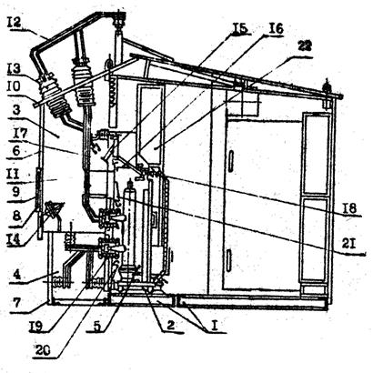
Fig. 7.2. KRUN cabinet of the K-47 series with VK-10 switches:
1 - frame; 2 - fixing unit of the roll-out cart; 3 - input compartment; 4 - compartment busbars; 5 - drawer compartment; 6, 7 - removable walls; 8 - door; 9 - a safety wall; 10 - roof; 11, 12 - tires; 13, 19 - bushing insulators; 14 - fans; 15, 16 - discharge valves; 17 - short circuits; 18 - locking lock; 20, 21 - protective curtains
The high-voltage part of the cell is divided into three compartments with the help of walls and a panel: input 3, busbars 4 and draw-out cart 5. On the rear side, the input 3 compartments and busbars 4 are closed by removable walls 7. In the wall of input compartment 3, for the convenience of routine maintenance, door 8, in the opening of which a safety net 9 is installed, which provides the possibility of safe inspection of equipment without removing voltage. The rear walls 6 and 7 of the input bays 3 and busbars 4, as well as the roof 10, serve simultaneously as the outer skin of the KRUN.
To balance the temperature in the input compartment 3, as well as to cool current transformers, their contact outputs, buses 12 and input / output insulators 13, two fans 14 are installed in the cells for a rated current of 1600 A, and the roofs of the cells with an air inlet for rated currents of 1000 and 1600 A are made of aluminum, which eliminates local overheating and contributes to better cooling of live parts.
To ensure more reliable operation of the automation, limiting the burning time of the open short-circuit arc, unloading valves 15 and 16 and short-circuiting (earthing disconnectors) are provided in the cells 17. Short-circuit-breaker 17 automatically shorts all three phases to ground, thereby shunting the short-circuit arc no more than 0 , 15 s.
Manual drives and roll-out trolleys are equipped with locking devices that prevent erroneous operations with them. The trolleys with circuit breakers, the earthing disconnectors of the busbars of the section section and in the input cubicle, as well as the disconnecting device in the auxiliary transformer cabinet, are locked using mechanical locking locks 18. In addition, an electromagnetic lock and signal unit are installed on the drive of the grounding disconnector in the input cubicle -contacts for locking the disconnectors on the side of the high and medium voltage power transformers.
In the compartment of the withdrawable carriage 5 are mounted: the drive of the ground disconnector 17, the pressure relief valve 15, the bushing 19 with the fixed part of the disconnecting contacts of the primary circuits.
Safe operation in the compartment of the withdrawable trolley 5 is ensured by protective shutters 20 and 21, which, when the trolley is rolled out of the working position into the repair position, are automatically closed, blocking access to stationary contacts that are under voltage. In the closed position, it is possible to lock the curtains with a lock.
To reduce the effect of low temperatures, an electric heater is installed in the compartment of the roll-out carriage 5, which automatically turns on when the temperature drops below -25 0 С, as well as at a positive temperature, but humidity above 80%.
Roll-out trolley 5 is a welded structure on which high-voltage equipment with disconnecting contacts is installed, determined by the connection circuit of the primary circuits. A bracket is installed on the trolley frame, which, when driving in and out of the trolley, controls the operation of the shutter mechanism, and a latch that fixes the trolley in the operating and control positions. The latch is actuated by the pedal. From the control position to the working and vice versa, the trolley is moved with the help of a lapping arm. From the test position to the repair position and vice versa, the trolley moves manually.
The relay cabinet 22 is a rigid welded structure installed above the compartment of the roll-out carriage 5. Alarm, measurement and manual control devices are installed on the cabinet door. The remaining low-voltage equipment is mounted on a fixed panel inside the cabinet. Secondary switching equipment for auxiliary needs, central alarm and automatic frequency unloading is mounted in relay cabinets installed in the control corridor along the front wall.
In switchgear intended for installation on complete transformer substations, relay cabinets with protection equipment for power transformers and medium voltage connections are additionally installed in the unit. In this case, inter-cabinet installation of secondary circuits is performed within the unit.
The control corridor is made prefabricated from separate elements, has general lighting, made using incandescent lamps, using closed semi-hermetic lamps. For ease of maintenance, installation of staircases, railings and stairs from both sides of the RU is provided.
The auxiliary transformer cabinet can be connected to the switchgear busbars through the cell of voltage transformers, or to the input to the input switch. The TSN cabinet is installed between the switchgear and the power transformer, opposite the input cell, on a separate foundation. The electrical connection of the TSN cabinet with relay cabinets installed in the switchgear corridor is carried out using a cable.
The high-frequency communication cabinet is made similar to the TSN cabinet, freestanding. It is designed to accommodate communication equipment and telemechanics. The cabinet contains: electrical equipment shield, table, electric heater, battery compartment, exhaust pipe.
In cells K-47, in order to prevent incorrect operations during the repair, maintenance and other works, locks were made to prevent:
Moving the withdrawable trolley from the test position to the working position with the blades of the grounding disconnector turned on;
Turning on the oil switch when the withdrawable trolley is located between the operating and control positions;
Moving the withdrawable trolley from the working position to the control one and vice versa when the oil switch is on;
Inclusion of the grounding disconnector in the sectioning cell with the circuit breaker at the working position of the withdrawable carts of the sectional switch and sectional disconnector;
Turning on the earthing switch of the section busbars when the input or section switch is turned on;
Switchgear Type USN-10 It is intended for reception and distribution of electrical energy of an alternating three-phase current with a frequency of 50 Hz and a voltage of 6, 10, 15, 20 kV. USN-10 is used as distribution points of urban and industrial substations, for electric networks of industry, agriculture, power plants and electrification of railway transport.
Switchgear type USN-10 are one-way service panels (there are options and two-way service) in a metal casing. Cells can be made in three-compartment (with each cell having a depth of 1000 mm) or four-compartment (depth of 1400 mm). All compartments (automation, circuit breaker, cable, bus) are separated from each other by metal partitions. Degree of protection of the enclosure of the switchgear cabinet IP40. The cells are designed for indoor use at temperature conditions from - 50 to +40 0 C.
In switchgear type USN-10, vacuum or gas-insulated circuit breakers can be used by manufacturers: Tavrida-Electric, Siemens, ABB, Schneider Electric and others. Relay protection can be installed at any manufacturer (Siemens standard protection is used in standard versions). The used current transformers can be both Russian (OJSC Sverdlovsk Plant of Current Transformers, OJSC Samara Transformer), and European production (for example, ABB).
There are shutters and closing contacts, automatically controlled from the cart. The removable two-layer design of the secondary circuit compartment allows the installation of automation components and the secondary circuits themselves, regardless of the installation of the cell body and power equipment. The auxiliary circuits are designed with alternating and direct current current for the operational voltage of 110 and 220 V.
The USN switchgear consists of different cells interconnected. The electrical connection of the cells inside the shield is carried out by busbars. Permanent electrical connection of all metal cases is ensured by connecting the galvanized cell case to the main grounding busbar of the switchgear. The cables of the secondary circuits pass through the shield above the automation compartments. These cables can be connected on either side, as well as on the top and bottom of each cell. The cell is a grounded metal shell that meets the requirements of the IEC-298 standard.
This is an “armored type” cell, all compartments are separated by metal partitions from each other:
Busbars (insulated or without insulation);
Withdrawable element (switch, disconnector trolley or voltage transformer trolley);
High voltage cable connections, earthing switch, sensors and possibly voltage transformers;
Insulation between the conductive parts is ensured by air gaps. The fuse switch compartment for protecting auxiliary transformers is also divided into two high-voltage compartments - the busbar compartment and the common compartment for cable connection and the load switch drive. The load switch is stationary.
Flat busbars for currents up to 3150 A are mounted in the busbar compartment (Fig. 7.3). For special orders or tropical versions, they are coated with protective insulating material. Tires are mounted on special epoxy insulators. The special protective cover opening up does not allow to create a big pressure at emergence of an electric arch. With a special order, it is possible to supply cells with isolated busbar compartments. For this, special bushing insulators are used.
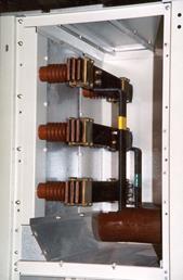
Fig. 7.3. Busbar compartment
The vacuum circuit breakers BB / TEL-10-20 / 1000A, BB / TEL-10-20 / 1600A (Tavrida Electric) or NX are mounted in the compartment of the switch ACT 2500A (Siemens) (Fig. 7.4).
 |
|
| BB / TEL-10-20 / 1000A | Nx ACT 2500A |
Fig. 7.4. Switch compartments
Any of these switches, having disconnected all locks with closed doors, can be rolled out on the cart.
Equipment located in the circuit breaker compartment:
Feedthrough insulators with contacts;
Automatic insulating curtains covering the main contacts;
Mechanical interlock system between circuit breaker and ground;
Channels for mounting secondary circuit cables on both sides of the cell;
Block contacts of the position of the switch trolley;
Socket secondary circuits.
The cable compartment is shown in fig. 7.5.
Approach to the cable compartment is allowed from the front (for the delivery of cells with one-way service) or the back of the cell (two-way service).
In the compartment are installed:
Earthing switch "quick action" with a spring mechanism and block contacts, controlled by a mechanical manual drive;
Three current transformers;
Transformer of zero sequence;
Three voltage transformers;
Capacitive voltage sensors on the cable;
Tires for connecting up to 6 cables.
By reducing the compartments of the busbars and the circuit breaker, a convenient approach to the cable compartment has been achieved. It occupies up to 45% of the volume of the entire cell and it is possible to connect six cables per phase. In the cells there are special cable holders with variable mounting dimensions in the horizontal direction. Standard cells come with lighting in the cable compartment.
Fig. 7.5. Cable compartment
The automation compartment (Fig. 7.6) is fully and reliably protected from other main circuit compartments. The removable two-layer compartment design allows the installation of secondary circuits and automation components, regardless of the installation of the cell body and primary equipment. The possibility of testing the operation of the circuit breaker in the rolled out state is provided. In the compartment are installed: terminal blocks of secondary circuits intended for connections with other cells; measuring instruments, protective relays, position indicators, automatic switches; multifunctional microprocessor protective relays.
Fig. 7.6. Automation compartment
The cells are supplied with "quick action" earthing switches with a spring mechanism designed to ground outgoing cables or busbars. The earthing switch is operated with the cells closed. The mechanical interlock allows the earthing switch to be switched on only if the circuit breaker is in an isolated state. The cells can be equipped with an electromagnetic interlock that does not allow the inclusion of an earthing switch in the presence of a high voltage on the cable.
The grounding of the circuit-breaker trolley is made through unpainted galvanized surfaces of its housing and cell structure (at short-circuit currents of 20 kA).
In fig. 7.7, a cell 800 A (1000 A with cooling of the switch contacts) with a BB / TEL 1000 A vacuum circuit breaker is shown, in fig. 7.7, b shows a 630 A cell with an ISARC2-12 630 A load switch.
Fig. 7.7. Switchgear cubicle type USN-10
KRU of the K-59 series are made for the most various operating conditions:
For outdoor use of switchgear (outdoor installation) in a temperate climate - K-59U1 series, in cold climates - K-59HL1 series, in tropical climates - K-59T1 series, as well as switchgear with special electrical circuits for powering drilling installations - series K-59BRHL1 or K-59BRT1 (complete with switchgear for drilling rigs, a slide frame can be supplied that acts as a foundation and allows you to transport switchgear over short distances);
For indoor use (indoor switchgear) - K-59UZ, K-61UHLZ, KSO-96UZ series.
The main specifications cells of types: K-59U1, K-59KHL1, K-59UZ, K-59T1, K-59BRKHL1, K-59BRT1, KSO-96UZ (manufacturer of OJSC Samara Electroshield Plant) are presented in Table. 7.1. The switchgear unit of the K-59 series is shown in Fig. 7.8
Table 7.1
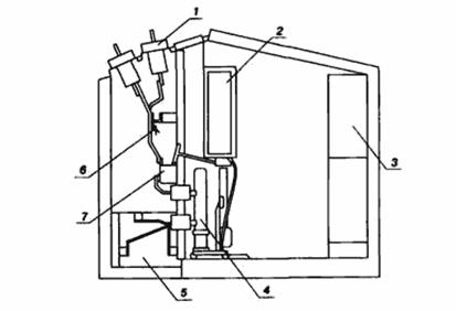
Fig. 7.8. KRU cell K-59 series:
1 - bushing insulator; 2 - relay cabinet; 3 - block relay cabinets;
4 - high voltage switch; 5 - compartment busbars;
6 - grounding disconnector; 7 - current transformer
All outdoor switchgear series have a closed control corridor (this makes it possible to service under any weather conditions), the location of high-voltage switches on withdrawable parts, automatic control of electric heating at low temperature and high humidity.
For each climatic version of KRUN, there are options with normal and reinforced external insulation (categories A and B according to GOST 9920-89). Switchgear is operable at wind speeds up to 40 m / s.
Units and components of switchgear for repair and modernization of existing electrical equipment:
Roll-out parts of switchgear:
With oil switch VK-10 (630 A, 20 kA; 1000 A, 20 kA; 1600 A, 20 kA; 630 A, 31.5 kA; 1000 A, 31.5 kA; 1600 A, 31.5 kA);
With oil switch VKE-10 (630 A, 20 kA; 1000 A, 20 kA; 1600 A, 20 kA; 630 A, 31.5 kA; 1000 A, 31.5 kA; 1600 A, 31.5 kA);
With a vacuum circuit breaker VVE-M 10-20 (1600 A, 20 kA);
With a BB / TEL vacuum switch (800 A; 8.0, 12.6, 16.0. 20.0 kA; 6 or 10 kV, with or without surge arrester);
Auto-gas load switch VNA - 10 / 630U2;
Socket contact type "Tulip" (1600 A, 20 kA; 630-1600 A, 31.5 kA);
The fixed part of the detachable contact with the bushing (630 A, 20 kA; 1000 A, 20 kA; 1600 A, 20.0 and 31.5 kA; 630 and 1000 A, 31.5 kA; 1600 A, 31.5 kA);
Light sensor of arc protection (short-circuit current 0.5 - 31.5 kA);
Block locks Z1M and Z2M and key K.
The use of the above KRUN allows you to drastically reduce the time and cost of the construction of substations 6-10 kV due to the refusal to build the building necessary to accommodate the indoor switchgear
The design of the switchgear of the indoor installation of the K-59UZ and K-61UHLZ series provides for bilateral maintenance; high-voltage switches are located on withdrawable parts.
The design of the switchgear of the indoor installation of the KSO-96 series is designed for one-way maintenance with stationary equipment.
The grid of the main switchgear circuits of the K-59UZ series switchgear provides the ability to replace, if necessary, the switchgear of the K-104, KM-1F, KR-10/20 series, as well as docking with them when expanding existing switchgears. The grid of the K-61 series switchgear main circuit diagrams is made taking into account the possibility of using thermal and nuclear power plants in switchgear for their own needs. There is a variant of busbar input cells and sectioning cells for a rated current of 3150 A for use in one switchgear with switchgear cells of the K-59UZ series. The grid of the main switchgear circuits of the KRU-KSO-96 series is made taking into account the possibility of their use instead of KSO-285, KSO-292, KSO-366, KSO-386 and KSO-392.
Circuits of protection, automation, control and signaling of switchgear are carried out using electromechanical devices, microelectronic equipment, microprocessor technology.
The structure of the symbol for switchgear cabinets of the K-59 series:
K-59 - K-59 series cabinet
ХХ - cabinet circuit number on the main circuit diagram grid
XX - type of built-in switch:
VK-10, VKE-10 - not indicated,
VVE-M-10, GDP-10, VV-10 - the letter "B",
BB / TEL-10 - the letters "VT",
VBKE-10 - the letters "WB",
Fg-1 - the letter "G".
ХХХ / - value of rated current, A; for cases ТН and ТСН - the value of the rated voltage, kV.
ХХ - thermal resistance current value, kA; for TSN cabinets - rated power of the transformer, kVA,
X - type of drive circuit breaker (spring is not indicated, electromagnetic - the letter "E"),
Examples of conventions:
K 59-01-1600 / 31.5 E HL1B - K-59 switchgear cabinet with a VKE-10 type switch, made according to the main circuit diagram 01, for a rated current of 1600 A, for a current of thermal resistance of 31.5 kA, climatic version ХЛ1, with external isolation of category B;
K 59-25-10 / 20 UI - K-59 switchgear cabinet manufactured according to the main circuit diagram 25 for a rated voltage of 10 kV and a thermal resistance current of 20 kA, climatic version UI with external insulation of category A.
Gas-insulated switchgear (GIS), depending on the filling scheme, are a complex of devices (cells, individual modules and products necessary for connecting overhead and cable lines).
The cells and modules consist of individual elements enclosed in sealed metal shells of a cylindrical or spherical shape filled with SF6 gas. For jointing, the shells of the elements have flanges and nozzles, contacts and seals.
According to the functional purpose, the switchgear cells can be linear, bus-connecting, voltage transformers and sectional, with one or two busbar systems. Cells, individual modules and elements allow the possibility of assembling switchgear according to various electrical circuits.
Switchgears without overhead lines are designed to operate at altitudes up to 2000 m.
Given the design features of the switchgear, it is possible to distinguish the main areas of their application, which are currently clearly defined:
Large cities, where due to the density of buildings, the high cost of land and the need to introduce voltage in the central regions (mainly through underground cables), there is simply no alternative to switchgear, the construction of substations is possible in the form of separate buildings, as well as in the form of basement, underground structures;
Hard-to-reach areas, especially permafrost, with fully automated substations;
Objects of metallurgy and chemistry, as well as thermal power plants with a highly polluted atmosphere;
Coastal areas with salt fogs;
Rocky hydropower stations with limited or difficult to develop substation areas;
Resort areas;
Substations with ultra-high voltage (750 kV and higher), where the operation of traditional equipment is very difficult, including for environmental reasons, and the equipment itself cannot be performed with the necessary reliability characteristics.
The current level and manufacturing technology of switchgear allows for a sufficient degree of reliability to produce switchgear in a common casing for three phases up to voltages of 500 kV, however, currently it is generally accepted to manufacture switchgear in a common casing up to voltages of not more than 170 kV, which provides the most optimal construction of substations.
On the other hand, there is a tendency to combine different devices in one sealed compartment, for example, a circuit breaker with current transformers, busbars with disconnectors and grounding, etc.
The combination of different elements is determined only by the criterion of reliability and ease of use, since in some cases it generally excludes the possibility of the output of individual elements for repair.
Substations with switchgear up to 220 kV mainly have a transverse cell arrangement with alternating poles extending into one service corridor, although in domestic practice there have been cases of placement of gas-insulated switchgear, in each row of which only the phases of the same name are installed.
Such a construction is sometimes convenient with a very large number of cells to reduce gas volumes. In addition, with this construction, the switchgear can be placed in the form of a three-beam star or on different floors in the case of cramped buildings.
In some cases, to reduce the cost of switchgear, busbars can be made in the open version (hybrid substations).
The classification of switchgear cells is carried out according to the following criteria:
According to the nominal voltage and purpose: L - linear, ТН - voltage transformer, С - sectional and Ш - bus-connecting;
By the number of busbar poles in one element: single-phase and three-phase;
By the number of busbar systems: with one or two systems;
According to the location of the switch: horizontal or vertical; all other elements of the cell in the first case are located above the switch, or below it, or next to it, and in the second case next to the switch;
By the type of external connections: with cable entry, with air entry, with current lead;
By the mutual arrangement of the poles of the cell: longitudinal, transverse or combined;
By mutual connection between the poles: in a single-pole or three-pole version;
By the nature of the installation.
In fig. 7.9 presents electrical schematic diagrams of switchgear cells with one busbar system: a - a linear cell; b - transformer cell; c - sectional cell.
Electrical schematic diagrams of switchgear cells with two busbar systems are shown in Fig. 7.10: a, b - the cell is linear; in - a cell busbar; g - cell voltage transformers.
Domestic switchgears are manufactured in only one climatic version and only for one category of placement, namely UHL4 1-35 ° С, i.e. for indoor installation with artificially controlled climate (without air conditioning). The air temperature in the room where the switchgear is installed must not be lower than 1 ° C. It is recommended to have a relative humidity of not more than 80% and a temperature close to 20 ° C in the switchgear inspection room.
Fig. 7.10. Electrical schematic diagrams of SF6 switchgear cubicles with two busbar systems:
KE - bus tire; QS - disconnector; QSG - grounding;
TA - current transformer; Q - switch; TV - voltage transformer
Installation of switchgear is carried out in rooms, the walls, ceiling and floor of which are painted with dust-forming paint. Dust in the room is not permissible. Dustiness of air no more than 15 mg / m 3. All openings, cable ducts and other recesses must be covered with removable covers. The premises should be equipped with filters to prevent the ingress of dust, and also have good lighting. The maximum permissible concentration of SF6 in the air of the working area is not more than 5000 mg / m 3 or 0.08% by volume (GOST 12.1005-88 "General sanitary and hygienic requirements for the air of the working area", TU 6-02-1249-83 "Elegaz increased pure you ").
The safety of personnel during operation and repair of switchgear must comply with the requirements of GOST 12.2.007.0-75, GOST 12.2.007.3-75 and GOST 12.2.007.4-75. Safety measures when working with decomposition products of SF6 gas, in particular, their regeneration, are established in RD 16-066-83 “High-voltage electrical equipment. Technical requirements to production and control methods to ensure the quality of SF6. ”
“The rules for the operation of consumer electrical installations and the safety rules for the operation of consumer installations” comply with RD 34.20.501-96.
Incorrect operation of switching devices is excluded by means of electrical, mechanical and gas-technological interlocks that do not allow:
Disconnecting and turning on the disconnector (s) when the switch is on;
Switching on the earthing switch (s) when the disconnector is turned on and turning on the disconnector when the switch is on (grounding switches on);
Turning the switch on and off when the density (pressure) of the SF6 gas in the switch tank falls below the lower limit and the compressed air pressure in the drive tank (in the case of a pneumatic or pneumohydraulic drive) outside the lower and upper limits;
Inclusions of the earthing switch of busbars with voltage on the tires.
The metal structures that serve as the base of the switchgear, each pole of the switchgear and all enclosures of the cabinets have a ground for connecting the grounding conductor, protected from corrosion and grounding clamp in accordance with GOST 21130-75. The shells of the elements of each pole are electrically connected to each other so as to ensure the safety of service and a fixed path of the currents induced in the shells when grounding the terminal ground clamps of the pole. In this case, the shells are isolated from the metal base.
The shells must comply with the requirements of the "Rules for the design and safe operation of pressure vessels". In the shells of elements under pressure of SF6 gas, protection against excessive pressure increase must be provided, or the material and strength of the shells must be such that there is no need for protective devices. One of the methods of protection is the division of poles into compartments; with a significant increase in pressure in one of the compartments, the disk insulator separating the compartments is destroyed, as a result of which the volume occupied by SF6 gas increases, and the pressure in the compartment decreases. Another method of protection is the installation of safety bursting discs on the compartments.
The appearance of an internal arc with a duration not exceeding 0.5 s should not cause breaks in the compartment or the shell as a whole, and with a duration of less than 0.1 s, burn holes in the shell.
If the SF6 pressure in the compartments is accidentally lowered from normalized to atmospheric, the insulation of the main circuits of 110 and 220 kV relative to the ground must withstand for 15 minutes a voltage equal to the phase maximum operating voltage.
The mechanical life of each of the switching devices built into the cells up to overhaul - at least 10,000 VO cycles for circuit breakers and 4,000 VO cycles for disconnectors and earthing switches (B - random pause - O).
The average cell service life before the first average repair is at least 15 years, and before decommissioning is at least 30 years.
An example of a symbol for gas-insulated gas cells YaEG-X-XX-X / X-X3 UHL4:
YEG - gas-insulated cell with hydraulic drive;
X - OS: three phases in a common casing (may be absent); unified;
X - 110, 220, 500 rated voltage, kV;
X - cell, VO - bypass switch, LO - linear with a bypass system of busbars, L - linear; ТН - voltage transformers, С - sectional, Ш - bus-connecting;
X - rated breaking current, kA (except for voltage transformer cells);
X - rated current, A;
X - 1 or 2 (one or two busbar systems);
З - opposite phases in a row;
Example of designating a linear cell with a bypass busbar system for 220 kV with a rated breaking current of 50 kA and a rated current of 2000 A with two busbar systems with three different phases in a row: "YaEG-220LO-50 / 2000- 23 UHL4. "
Normalized test voltages of gas-insulated apparatus under normal atmospheric conditions, i.e. at an air temperature of 20 ° C, atmospheric pressure of 101300 Pa (760 mm Hg) and an absolute humidity of 11 g / m 3 (relative humidity 63%) according to GOST 1516.1-76 and GOST 20690-75 are given in table. 7.2.
Table 7.2
| Rated voltage, kV | Test voltage kV | ||||||
| Full lightning impulse of positive and negative polarity, maximum value 1 | Switching pulse of positive and negative polarity, maximum value 2 | Industrial frequency, one-minute current 3 | |||||
| GOST | IEC | regarding land | regarding land | between open contacts | regarding land | between open contacts | |
| - | - | ||||||
| - | - | - | |||||
| - | - | ||||||
Notes:
1 For electromagnetic VTs, these standards also apply to cut-off lightning impulse
2 The indicated voltages relate to insulation in the dry state, and for GIS bushings, air - SF6 gas of category 1 - also applies to insulation relative to the ground in the rain
3 The same pole of a switch or disconnector.
In the table. 7.3 the basic parameters of the cells of the following types are presented: YaEO-110, YaEG-220, YaEU-3ZO, YaEU-500.
Table 7.3
| Parameter Name | Parameter value for cell type | |||
| YaEO-110 | YaEG-220 | YaEU-3ZO | YaEU-500 | |
| 110/126 | 220/252 | 330/362 | 500/525 | |
| Lightning impulse test voltage relative to the ground, kV | ||||
| Rated current frequency, Hz | 50/60 | 50/60 | 50/60 | 50/60 |
| Parameters of through short circuit current: | ||||
| thermal current, kA | ||||
| electrodynamic resistance current, kA | ||||
| rated duration of a short circuit in an external circuit, s | ||||
| Nominal DC voltage of control circuits (CC) and auxiliary circuits (CC), V | ||||
| SF6 leakage from the cell per year,% |
GIS cells type YAGK-110 They are designed to receive and distribute electricity in alternating current networks with a nominal voltage of 110 kV and a frequency of 50 Hz with a grounded neutral. Earth fault coefficient not more than 1.4. Cells of the YAGK-110 type, individual modules, and the original elements that are part of the switchgear are designed to operate in normal and emergency modes of switching operations, measurements and protection.
Cells are classified according to the functional purpose of the cells, the number of busbars.
The structure of the symbol YAGK-110 [*] - [*] 3-UHL4:
I am the cell;
G - gas (SF6);
K - compact;
110 - rated voltage, kV;
[*] - cell design: (L - linear, W - busbar; C - sectional; VT - voltage transformers);
[*] - the number of busbars (1 - one tire system, 2 - two tire systems);
3 - three-phase bus;
A cell of any type consists of three poles mounted on one common frame, a hydraulic actuator for the circuit breaker (one per three poles), actuators of disconnectors and earthing switches (one per three poles), busbars (one or two, depending on the cell type) and one hardware cabinet (SHA). The cabinets contain the equipment of the signaling, blocking, remote three-pole electrical control circuits.
The pole of the cell, in addition to the cell of voltage transformers, consists of the poles of switching devices (circuit breaker, disconnectors, earthing switches), a measuring current transformer, bellows expansion joints.
The pole of the cell of voltage transformers consists of poles of disconnectors, grounding, voltage transformer, connecting sections and bellows expansion joints.
Switchgears are equipped with auxiliary equipment and devices that ensure their normal maintenance. These include: equipment for emptying, drying, liquefying, regenerating and filling gas compartments with SF6 gas, equipment for detecting gas leakage points, registration devices for switching (on demand) and mechanical resources of the circuit breaker.
Electrical switchgear, disconnectors and earthing switches are provided in the switchgear. In fig. 7.11 presents a mobile SF6 substation based on the cell
YAGK-110 kV.
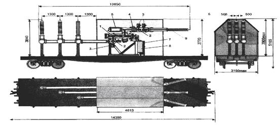
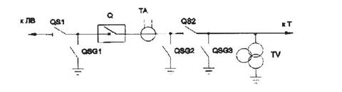
Fig. 7.11. Mobile high-voltage gas-insulated substation based on YAGK-110 kV in a thermostatic enclosure:
a - general view and overall dimensions; b is a schematic diagram;
1 - switch; 2 - disconnector; 3 - ground electrode; 4 - current transformer;
5 - voltage transformer; 6 - thermostatic shell;
7 - hardware cabinet; 8 - hydraulic drive; 9 - input "air-SF6"
The various elements of the cells can be combined into gas compartments by design, operation features, installation, repair of the gas circuit, and by transportation conditions into transport units. Cells or their transport blocks are transported filled with SF6 gas or nitrogen, with a slight overpressure.
Technical characteristics of the switchgear of the YAGK type are presented in table. 7.4 (manufacturer of OJSC "Energy Mechanical Plant", St. Petersburg).
Table 7.4
| Parameter Name | YAGK-110 | YaEG-220 | YaEU-330 | YaEU-500 | YaEU-800 |
| Rated voltage and corresponding maximum operating voltage, kV | 110/126 | 220/252 | 330/362 | 500/525 | |
| Test voltage short-term (one-minute) alternating, kV | |||||
| Test voltage of a full lightning impulse relative to the ground, kV | |||||
| Test voltage of a switching impulse concerning the earth, kV | |||||
| Rated current, A busbars taps | 3150-8000 2000-4000 | 3150-6000 2000-4000 | |||
| Rated current frequency, Hz | 50/60 | 50/60 | |||
| Lower limit of the overpressure of SF6 gas at a temperature of 20 ° C, MPa (kgf / cm 2): for circuit breaker | 0,35 (3,5) | 0,50 (5,0) 0,70 (7,0) | 0,50 (5,0) 0,60 (6,0) | 0,62 (6,2) | 0,62 (6,2) |
| for voltage transformers | 0,40 (4,0) | 0,39 (3,90) | 0,39 (3,90) | 0,45 (4,5) | 0,40 (4,0) |
| for other modules | 0,25 (2,5) | 0,29 (2,90) | 0,29 (2,90) | 0,45 (4,5) | 0,40 (4,0) |
| Switch type | Vg-110 | VGGK-220 | VGK-330 | VGK-500 | VGK-800 |
| Rated breaking current, kA | 40/50 | 40/63 | |||
| The number of breaks per pole | 1/2 | ||||
| Switching resource. Allowed number of operations "O / V" in the range from 60 to 100% I o, nom and I in | 20/10 | 20/10 | 20/10 - 15/8 | 18/9 |
The end of table 7.4
| Total time of shutdown, s, no more | 0,055 | 0,055 | 0,055 | 0,04 | 0,04 | |
| Type of drive | hydraulic | |||||
| Own shutdown time, s | 0,030 | 0,030 | 0,030 | 0,030 | 0,017 | |
| Own turn-on time, s, no more | 0,10 | |||||
| Current transformer | ||||||
| Rated primary current, A | 600-1200-2000 | 600-1200-2000 | 1000, 2000, 1500, 3000, | 1000, 2000, 1500, 3000, 4000, | ||
| Rated secondary current, A | ||||||
| The number of secondary windings | ||||||
| Secondary winding for measurements | 15-20-30 VA class 0.5-0.2-0.2S | 30 VA class 0.5-0.2-0.2S | 30 VA class 0.5-0.2 | 30 VA class 0.5-0.2 | 30 VA class 0.5-0.2 | |
| Secondary winding for protection | 15 VA class 10P 15-20-30 | 30 VA class 10P 25-25-26 | 30 VA class 10P, 21 | 30 VA class 10P, 21 | 30 VA class 10P, 21 | |
| SF6 gas leak per year,% of mass, not more than | ||||||
| Overall dimensions of a cell, mm width depth height | ||||||
test questions
1. State the classification of switchgear and the requirements for their designs.
2. Tell us about the device and applications of switchgear KRU2-10P, K-47, USN-10, K-59.
3. What are the elements of the drawout compartment.
4. What are the interlocks between disconnectors and switches designed for?
5. What design features do switchgears in switchgear have
with switches on withdrawable carts?
6. Why are the switchgear cells divided into several compartments?
7. What positions can a trolley with a switch in a switchgear occupy?
8. Tell us about the advantages of complete switchgear.
9. State the classification of the switchgear cells. What are the applications of the switchgear.
10. What design features do the switchgear have?
11. Draw the electrical schematic diagrams of the switchgear cells with one and two busbar systems.
Literature
1. Aliev I.I. Electric devices: reference book / II. Aliev, M.B. Abramov. - M.: Publ. RadioSoft Enterprise, 2004. - 256 p.
2. Doroshev K.I. Switches and measuring transformers in switchgear 6 - 220 kV / K.I. Doroshev. - M .: Energoatomizdat, 1990 .-- 152 p.
3. Korotkov G.S. Repair of equipment and apparatus for switchgear / G.S. Korotkov, M.Ya. Members. - M.: Higher School, 1990. - 270 p.
4. Rozhkova L.D. Electrical equipment of stations and substations / L.D. Rozhkova, V.S. Kozulin. - M .: Energoatomizdat, 1987 .-- 648 p.
5. Rumyantsev D.E. Modern vacuum switching electrical equipment of electrical networks and substations: textbook. - method. allowance / D.E. Rumyantsev. - M .: IPK civil service, 2000. - 72 p.
6. Handbook of electrical installations of high voltage / ed. I.A. Baumstein, S.A. Bazhanova. - M .: Energoatomizdat, 1989 .-- 768 p.
7. Tarasov A.I. Modern electrical SF6 equipment: textbook. - method. allowance / D.E. Rumyantsev, A.I. Tarasov. - M .: IUE GUU, VIPKenergo, IPK civil service, 2002. - 144 p.
8. Operation of electrical apparatus / G.N. Alexandrov, A.I. Afanasyev, V.V. Borisov et al. - St. Petersburg: Publishing House PEIPK, 2000 .-- 307 p.
9. The electrical part of stations and substations / ed. A.A. Vasilieva. - M .: Energoatomizdat, 1990 .-- 576 p.
10. The electrical part of power plants / ed. S.V. Usova. - L .: Energoatomizdat, 1987 .-- 616 p.
The layout of the switchgear (RU) is carried out after the selection and development of the electrical circuit of the substation, the selection of equipment, live parts and power transformers.
According to the method of construction of substation switchgear, there can be:
- prefabricated for indoor installation;
- prefabricated for outdoor installation;
- complete for indoor installation (switchgear);
- complete for outdoor installation (KRUN). ;
Modern switchgear of large substations have a combined design: partly as prefabricated and partly as complete.
Closed Switchgear Design
- The construction part of the indoor switchgear is made of standard reinforced concrete elements. The dimensions of the switchgear buildings should be multiple: length - 6 m, width - 3 m, height - 0.6 m.
- Electrical apparatuses and live parts are placed so that the smallest insulating distances in the air between conductors of different phases, as well as from conductors to grounded structures and parts of the building, are maintained. Unprotected live parts must not be accessible for accidental contact.
Practically recommended distances between the axes of the phases are:
for 6 kV - 250-500 mm; for 10 kV - 300-700 mm; for 35 kV - 500-700 mm; for 110 kV - 1250-1600 mm; for 220 kV - 3000 mm.
Non-insulated live parts located above the floor at a height of less than 2.5 m in 6-10 kV installations and 2.7 m in 35 kV installations should be fenced with grids, and the passage height under the grid should be at least 1.9 m.
- The length of the switchgear is determined by its scheme, the adopted busbar configuration, the number and size of cells.
Service corridors and control corridors are provided for servicing prefabricated switchgear and moving equipment. The width of the service corridors in the light between the fences is taken at least 1 m for unilateral equipment and 1.2 m for two-sided. In the control corridors, the indicated dimensions should be increased respectively to 1.5 and 2 m. The number of exits from the switchgear is taken based on its length: with a switchgear length of up to 7 m, one exit is allowed so that the distance from any point of the corridor to the exit is no more than 30 m.
Domestic plants produce switchgear with one-sided and two-way service. In case of two-way switchgear maintenance, the width of the passage from the rear side of the switchgear must be at least 0.8 m. The location of the switchgear cabinets in the switchgear building can be single-row and double-row. With a single-row arrangement of the switchgear, the width of the control corridor should be greater than the length of the withdrawable carriage by at least 0.6 m, but not less than 1.5 m, and with a two-row arrangement, the length of the trolley is 0.8 m more, but not less than 2 m.
- Current-limiting reactors are located in separate switchgear chambers. The placement of reactors in transformer circuits can be performed in extensions to the reactor building with a horizontal phase arrangement in a row or along a triangle. Linear and group reactors are placed vertically in cells in the form of columns of three phases. The presence of linear reactors, as a rule, leads to the need for the construction of a mixed type switchgear.
- Power and control cables at step-down substations of small and medium power can be removed from the switchgear either through pipes, or before they go out, they can be laid in cable channels closed with removable plates. With a large number of cables, special cable structures are arranged: tunnels, cable cellars. Cables are laid along the walls on structures made in the form of shelves. The height of the tunnel in the light should be at least 1.8 m. The smallest distance in the light between structures for laying cables with their two-row arrangement is 1 m, from structures to the wall with a single-row arrangement of structures - 0.9 m.
- The connection from the transformer to the indoor switchgear is performed by the tires: through flexible connections or in the form of a bus bridge. Entrances to the RU building are made through bushing insulators. For low power transformers, a cable entry can be made.
Entrances to switchgear cabinets are performed in different ways: from above, from the side or from the back. Input circuits can also be very diverse: blind connection to the switchgear busbars, through a disconnector or plug disconnecting contacts and a switch. In this regard, the choice of inputs should be made according to the catalogs.
Development of the layout and design of switchgear
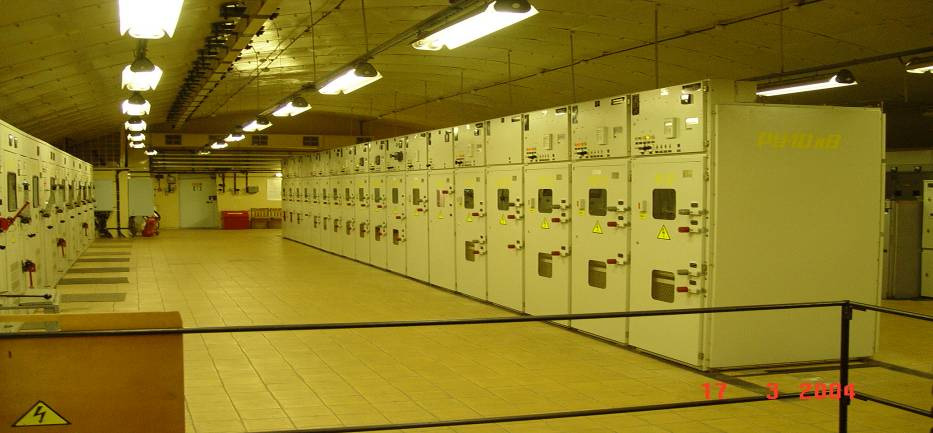
- Design development explores the choice of type of switchgear and comes down mainly to the layout of electrical equipment in switchgears and in cells.
The layout of electrical equipment in the switchgear consists of the placement of sections of busbars in the building of the switchgear, the distribution of cells of all connections within each section and the placement of electrical equipment within each cell (for combined switchboards). In this case, there should be no deviations from the previously developed electrical circuit.
The work on the layout of electrical equipment in RU is made out in the form of sketches - cuts in cells, floor plans and filling schemes, made by hand in pencil on graph paper.
Getting started, you must first determine the total number of all connections and their busbar disconnectors for each section of busbars, including intersection and busbar connections, grounding disconnectors on busbars, voltage transformers and all other connections provided for by the electrical connection diagram. For each section, the required number of cells or chambers is identified for placement of bus disconnectors, circuit breakers, reactors (taking into account the method of their installation), voltage measuring transformers, arresters, and other equipment. A circuit for filling the switchgear is compiled.
- The filling circuit clearly connects the electrical circuit with the design of the switchgear. It is done in pencil on graph paper. All devices and connections between them are shown in legendadopted for the circuits, within the circuits of those RU chambers in which they are installed. The drawing is not to scale. It shows in plan all the cameras, as well as corridors and walkways. The walls and partitions separating the chambers from each other and from the aisles and corridors, and the floors between floors are applied in thin solid lines. All floors are conditionally combined in one drawing.
In fig. Figure 2 shows the switchgear filling circuit corresponding to the simplified electrical circuit of the substation shown in Fig. 1. 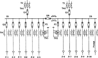
Fig. 1. Electrical connection diagram of switchgear 6-10 kV complete substations

Fig. 2. The scheme of filling the switchgear 6-10 kV
When determining the configuration of busbars and the location of the sections, ease of use and reliability requirements should be considered. In particular, both with a single-row and a double-row arrangement of the RU chambers, the sections along the building are located one after another, which allows you to separate the sections from one another by transverse partitions and to avoid the spread of the accident to other sections.
Along with the location of the section, the location of the busbar jumpers between the busbars of one section located on opposite sides of the control corridor, as well as intersectional communications, should be noted.
The next very important part of the layout is the location of the bushings in the transformer switchgear. The location of the chambers for these connections should be chosen so that the bus connections are short and straight. It is desirable to distribute the cells for the outgoing lines on both sides of the bushings so that the power flows from them are distributed in the busbars approximately equally on both sides of the bushings.
Chambers for voltage transformers, arresters, transformers place last, occupying free cameras.
The final stage in the design development is the ZRU plan, executed on a scale on sheet No. 2 of the graphic part of the project.
Open Switchgear Design
![]()
- In projects, as a rule, typical designs Outdoor switchgear, taking into account the possibility of further expansion of outdoor switchgear and the use at all stages of construction and operation of modern means of mechanization of work.
- In the outdoor switchgear, the devices are installed as low as possible to facilitate maintenance, but at the same time so as to exclude the possibility of accidental contact with live parts. Large-volume oil circuit breakers 110-220 kV can be installed on foundations 0.6-0.8 m high. Small-volume oil and air switches, disconnectors, current and voltage measuring transformers are installed on steel or reinforced concrete substrates with a height of 2-4.5 m. transport of heavy equipment at the outdoor switchgear site provides for concrete or railways.
- As conductors for busbars of the outdoor switchgear and branches from them, multiwire wires of grades A and AC are used, as well as rigid tubular tires. At voltages of 220 kV and higher, splitting of the wires is necessary in order to reduce the loss of corona.
The minimum allowable insulating distances in the air between conductors of different phases, as well as from conductors to grounded structures and parts of a building, are regulated by PUE.
Practically recommended distances between the axes of the phases are given in table. 1 in mm.
Table 1
Type of busbar switchgear |
Voltage kV |
|||
- The length of the switchgear is determined by its scheme, the adopted busbar configuration, the number and size of cells. The step of the cell depends on the type of equipment used. The recommended cell step is: for 35 kV - 6 m, for 110 kV - 8 m, for 220 kV - 11 m.The total length of the switchgear, taking into account the dimensions to the fence, is roughly defined as the product of the cell step by the number of cells increased by one.
The width of the switchgear depends on the selected substation scheme, the location of the switches (single row, double row, etc.) and power lines. In addition, access roads for road or rail should be considered.
Outdoor switchgear must have a fence not less than 2.4 m high.
- The supporting structures of the outdoor switchgear are made of profile steel, as well as of standardized reinforced concrete structures - columns, traverses, etc.
In the switchgear, live parts of the apparatus, busbar conductors and busbar branches to avoid intersections are placed at different heights of two and three tiers. With flexible wires, busbars are placed in the second tier, and branch wires in the third.
The minimum distance from the conductors of the first tier to the ground for 35 kV is 3100 mm, 110 kV - 3600 mm, 220 kV - 4500 mm.
The minimum vertical distance between the wires of the first and second tiers, taking into account the wire sag for 35 kV, is 440 mm, for 110 kV - 1000 mm, for 220 kV - 2000 mm.
The minimum distance between the wires of the second and third tiers for 35 kV is 1150 mm, for 110 kV - 1650 mm, for 220 kV - 3000 mm.
- Under power transformers and tank switches 110 kV and above, a layer of gravel is laid with a thickness of at least 250 mm, and oil drainage into the stormwater drainage system is provided. Reinforced concrete or brick partitions are installed between the transformers with a distance between them of less than 15 m, preventing the spread of fire.
Cables of operational circuits, control circuits, relay protection and automation are laid in channels located along the rows of equipment, as well as without burying them in the soil.
Development of the layout and design of outdoor switchgear
To select the design of the switchgear, you must have the following data:
The circuit of electrical connections at all voltages; types of electrical apparatus and sections of conductors; directions of approach of power lines; climatic conditions and nature of environmental pollution; restrictions on the territory, configuration of outdoor switchgear, terrain (if specified).
When assembling an outdoor switchgear, the total number of connections, the number of cells and their sizes are first determined.
The scheme for filling the switchgear is compiled. When drawing up the filling scheme, the directions of suitable power lines and the possibility of access to heavy equipment of hoisting-and-transport machines should be taken into account.
In the filling scheme, the mutual arrangement of bus systems and electrical devices is determined, the arrangement of devices in each cell. Particular attention is paid to the implementation of the shortest connections between switchgear of various voltages.
The principles of arrangement of circuit breakers in an outdoor switchgear (single or double row), the configuration of bus systems, as well as the number of tiers of conductors by the height of the outdoor switchgear are estimated by the area occupied by the outdoor switchgear, as well as its height and ease of maintenance of the switches.
The work on the arrangement of the switchgear is executed in the form of sketches, cuts in cells and filling schemes, made with a pencil on a graph paper by hand.
The final stage in the design development is the open switchgear plan and a section along one of the cells. The drawings use simplified graphic images of structural elements and apparatuses of the reactor, which on a scale reflect the overall dimensions of the equipment and the distance to live parts. Roads, auxiliary facilities and outdoor switchgear fencing are also plotted.


