LED rechargeable flashlight - diagram, repair, how to make. LED rechargeable flashlight - diagram, repair, how to make Dik an Lantern 0
SL.Elkin, Zhitomir
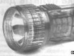
New rechargeable flashlight (AKF) made in Russia under the Fo-Dik brand, model AN 0-005, with Chinese disk batteries (Fig. 1) 
It worked somehow unstable, the batteries (AK) sometimes gave off electrical capacity, sometimes not. For more convenient operation (including for identifying malfunctions of the charger), an LED charge current indicator was installed in it, the diagram of which is shown in Fig. 2. 
The ACF worked fine for some time, and then the LED stopped lighting. Checking the LED VD3 and resistor R3 showed that they are working. The cause of the inoperability turned out to be a defect in the ballast capacitor C1, the actual capacity of which turned out to be an order of magnitude lower, i.e. 47 nF! In addition, defects in imported capacitors of this type are encountered in ACF repair practice, and quite often.
Since I didn’t have a new capacitor at hand, I decided to recharge the batteries (on the body of which are marked Ni-Cd CELL B280K) from a DC source. To speed up the charging process, I briefly set the charging current to 100 mA. And what was pleasing was that the AKs didn’t get warm at all! After a four-hour charge (recharging twice in capacity), I turned on the AK for discharge to a 3.5 V x 0.15 A light bulb, which shone for about 1.5 hours. From this I concluded that everything was fine with the AK. Well, if modern AKs do not heat up at a higher charge current (versus that accepted for sealed ones - 0.1 of the electrical capacity), I installed a ballast capacity twice as large, i.e. 1 µF.
I connected a 100 Ohm resistor in parallel to the existing shunt, reducing it by half. After 2-3 test connections to the network, the LED failed! It became clear that the dependence of the voltage drop across the shunt on the value of the capacitance is significantly nonlinear, so I installed a shunt with a resistance of 12 Ohms. When the ACF was connected to the network, the LED flashed and went out, although there was a charging current! This clearly confirmed the pulsed nature of the current change through the LED indicator in the circuit with capacitive ballast in the initial phase. 
I had to, as they say, return to “our sheep” - I carried out the selection of the shunt in a stationary mode on direct current. The resulting parameters are shown in row 1 of the table. 
However, after some time of operation of the ACF, the LED with a shunt resistor with a nominal value of 24 Ohms still failed!
It became clear that transient pulse processes (like the east) are a delicate matter, and that the reasons for the failure of the indicator (with a 1 µF ballast capacitor) would have to be seriously looked into.
Since failure of the LED from the application of reverse voltage is unlikely, since it is connected in series with the rectifier diode, I assumed that it fails during a series of pulses (“contact bounce” - this is how it is convenient to imagine the processes occurring in the circuit at the moment the ACF is connected to the network). It is then that the voltage drop across the shunt also increases, as a result of which the pulsed current through the LED, although briefly, significantly exceeds the permissible value, and this leads to its failure.
In order not to have to carefully select a shunt, the value of which may differ from the values of standard series resistors, to automatically limit the amplitude of the voltage pulse occurring on the shunt (and therefore on the LED), I decided to install a KS133A zener diode in parallel with it, using it as a suppressor.
To check the circuit solution, a circuit was assembled (Fig. 4) 
and measurements of the voltage drop across the shunt were carried out in various modes, to a certain extent simulating the nature of the change in current through the ballast capacitor during its initial charging. The measurements were carried out at direct current from a source with an adjustable output voltage at a constant shunt resistance value of 24 Ohms.
From line 2 of the table it is clear that even with a voltage drop across the shunt equal to 2 V, the current through VD2 is equal to the maximum.
That is why, to limit the current through the LED with a voltage drop across the shunt equal to 3.3 V (line 3 of the table), resistor R3 is introduced into the circuit in series with VD2.
As follows from line 3 of the table, the current through the LED when R3 is introduced also does not exceed 20 mA.
When the charger switches to stationary mode 2 (line 4 of the table), the current through VD2 with R3 connected in series decreases to 1.5 mA, which, when using the AL307A LED (red), is visually quite visible even in sunlight.
In order to check the reliability of the LED indicator in a circuit with a capacitive ballast, a modernized ACF (Fig. 5) 
was removed and installed in a power outlet 100 times in a row - no noticeable changes in the brightness of the glow were visually noticed. The LED indicator with a suppressor on the zener diode worked properly, the LED did not fail!
The experiment carried out allows us to draw a practical conclusion that, due to the nature of the transient processes occurring, for reasons of sufficient reliability, it is still possible to use a simple resistive shunt with a ballast capacitance of up to 0.5 μF for an LED indicator, and already at 1 μF and higher - only in combination with a shunt - suppressor - current-limiting resistor. 


Literature
1. Tereshchuk R.M. and others. Small-sized radio equipment. Radio Amateur Directory//Kyiv, Naukova Dumka, 1971.
2. Information sheet. Transient voltage suppressors // Radioamator. -1999.-Nc2.-C.3l
3. Tereshchuk R.M. etc. Semiconductor receiving and amplifying devices. Handbook of a birth lover//Kyiv, Naukova Dumka, 1988.
There are times in every person’s life when lighting is needed, but there is no electricity. This could be a simple power outage, or the need to repair the wiring in the house, or perhaps a forest hike or something similar.
And, of course, everyone knows that in this case, only an electric flashlight will help out - a compact and at the same time functional device. Now there are many different types of this product on the electrical equipment market. These include regular flashlights with incandescent lamps, and LED flashlights with rechargeable batteries. And there are a great many companies producing these devices - “Dick”, “Lux”, “Cosmos”, etc.
But not many people think about the principle of its operation. Meanwhile, knowing the structure and circuit of an electric flashlight, you can, if necessary, repair it or even assemble it with your own hands. Let's try to figure this out.
The simplest lanterns
Since flashlights are different, it makes sense to start with the simplest one - with a battery and an incandescent lamp, and also consider its possible malfunctions. The circuit diagram of such a device is elementary.
In fact, there is nothing in it except a battery, a power button and a light bulb. And therefore there are no special problems with it. Here are a few possible minor troubles that may result in the failure of such a flashlight:
- Oxidation of any of the contacts. These could be the contacts of a switch, light bulb or battery. You just need to clean these circuit elements, and the device will work again.
- Burning out of an incandescent lamp - everything is simple here; replacing the light element will solve this problem.
- The batteries are completely discharged - replace the batteries with new ones (or charge them if they are rechargeable).
- Lack of contact or broken wire. If the flashlight is no longer new, then it makes sense to change all the wires. This is not at all difficult to do.
LED flashlight
This type of flashlight has a more powerful luminous flux and at the same time consumes very little energy, which means that the batteries in it will last longer. It's all about the design of the light elements - LEDs do not have an incandescent filament, they do not consume energy on heating, which is why the efficiency of such devices is 80–85% higher. The role of additional equipment in the form of a converter involving a transistor, resistor and high-frequency transformer is also great.
If the flashlight has a built-in battery, then it also comes with a charger.
The circuit of such a flashlight consists of one or more LEDs, a voltage converter, a switch and a battery. In earlier flashlight models, the amount of power consumed by the LEDs had to match the amount produced by the source.
Now this problem has been solved using a voltage converter (also called a multiplier). Actually, this is the main part that contains the electrical circuit of the flashlight.

If you want to make such a device with your own hands, there will not be any special difficulties. Transistor, resistor and diodes are not a problem. The most difficult part will be winding a high-frequency transformer on a ferrite ring, which is called a blocking generator.
But this can also be dealt with by taking a similar ring from a faulty electronic ballast of an energy-saving lamp. Although, of course, if you don’t want to mess around or don’t have time, then you can find highly efficient converters on sale, such as 8115. With their help, using a transistor and a resistor, it became possible to produce an LED flashlight on a single battery.
The LED flashlight circuit itself is similar to the simplest device, and you shouldn’t dwell on it, because even a child can assemble it.
By the way, when using a voltage converter in the circuit on an old, simple flashlight, powered by a 4.5 volt square battery, which is no longer available for purchase, you can safely install a 1.5 volt battery, i.e. a regular “finger” or “little finger” one. battery. There will be no loss in luminous flux. The main task in this case is to have at least the slightest understanding of radio engineering, literally at the level of knowing what a transistor is, and also to be able to hold a soldering iron in your hands.
Refinement of Chinese lanterns
Sometimes it happens that a purchased flashlight with a battery (which appears to be of good quality) completely fails. And it is not necessarily the buyer’s fault for improper operation, although this also occurs. More often, this is a mistake when assembling a Chinese lantern in pursuit of quantity at the expense of quality.
Of course, in this case it will have to be remade, modernized somehow, because the money has been spent. Now you need to understand how to do this and whether it is possible to compete with the Chinese manufacturer and repair such a device yourself.
Considering the most common option, in which when the device is plugged in, the charging indicator lights up, but the flashlight does not charge and does not work, you can notice this.
A common mistake by the manufacturer is that the charge indicator (LED) is connected in parallel with the battery, which should never be allowed. At the same time, the buyer turns on the flashlight, and seeing that it is not lit, again supplies power to the charge. As a result, all LEDs burn out at once.
The fact is that not all manufacturers indicate that such devices cannot be charged with the LEDs turned on, since it will be impossible to repair them, all that remains is to replace them.
So, the modernization task is to connect the charge indicator in series with the battery.

As can be seen from the diagram, this problem is completely solvable.
But if the Chinese installed a 0118 resistor in their product, then the LEDs will have to be changed constantly, because the current supplied to them will be very high, and no matter what light elements are installed, they cannot withstand the load.
LED headlamp
In recent years, such a lighting device has become quite widespread. Indeed, it is very convenient when your hands are free, and the beam of light hits where the person is looking, this is precisely the main advantage of a headlamp. Previously, only miners could boast of this, and even then, to wear it, you needed a helmet, onto which the flashlight was, in fact, attached.
Nowadays, the mounting of such a device is convenient, you can wear it under any circumstances, and you don’t have a rather large and heavy battery hanging on your belt, which, moreover, must be charged once a day. The modern one is much smaller and lighter, and also has very low energy consumption.
So what is such a lantern? And the principle of its operation is no different from LED. The design options are the same - rechargeable or with removable batteries. The number of LEDs varies from 3 to 24 depending on the characteristics of the battery and converter.
In addition, such flashlights usually have 4 glow modes, not just one. These are weak, medium, strong and signal - when the LEDs blink at short intervals.

The modes of the LED headlamp are controlled by a microcontroller. Moreover, if it is available, even a strobe mode is possible. In addition, this does not harm LEDs at all, unlike incandescent lamps, since their service life does not depend on the number of on-off cycles due to the absence of an incandescent filament.
So which flashlight should you choose?
Of course, flashlights can be different in voltage consumption (from 1.5 to 12 V), and with different switches (touch or mechanical), with an audible warning about low battery. This may be the original or its analogues. And it’s not always possible to determine what kind of device is in front of your eyes. After all, until it fails and repairs begin, you cannot see what kind of microcircuit or transistor is in it. It’s probably better to choose the one you like and solve possible problems as they arise.
Authenticity Guarantee: Seller's Warranty
Flashlight Fo-DiK AN-0-003 performance is unknown... it looks like everything inside the batteries are of course no longer working
Flashlight Fo D and K
standard description:
FOR real postage costs - the buyer pays in full.
!!! ATTENTION After purchasing the lot, contact me within 3 days, payment within 7 days. Otherwise, I will be forced to leave a negative review in order to return the trading platform commission.
Before purchasing, be sure to look at the “ABOUT ME” page, it shows in more detail how best to pay and other nuances.
Dear customers! I would like to inform you about some of the nuances that may arise when purchasing my lots. All lots are also sold on other sites. And a situation may arise when during the day the lot will be sold on another site, and I will be able to remove it from auction only in the evening. And if you buy a lot on this day, I may not have it in stock. This situation occurs extremely rarely, but it is still advisable to inquire about the availability of the lot before purchasing. I apologize in advance if this situation arises.
Everything that I sell or buy, like any person, I try to further discuss in personal correspondence, especially the conditions for sending the goods, and of course the payment itself.. So, as always, everything changes and sometimes, as you want, you may not be able to ship the goods and receive payment , as well as send money in the usual and usual way to the buyer...
As a sample, let's take a rechargeable flashlight from the company "DiK", "Lux" or "Cosmos" (see photo). This pocket flashlight is small-sized, comfortable in the hand and has a fairly large reflector - 55.8 mm in diameter, the LED matrix of which has 5 white LEDs, which provides a good and large illumination spot.
In addition, the shape of the flashlight is familiar to everyone, and many from childhood, in a word - a brand. The charger is located inside the flashlight itself; you just need to remove the back cover and plug it into a power outlet. But nothing stands still and this flashlight design has also undergone changes, especially its internal filling. The latest model at the moment is DIK AN 0-005 (or DiK-5 EURO).
Earlier versions are DIK AN 0-002 and DIK AN 0-003, differing in that they contained disk batteries (3 pcs), Ni-Cd series D-025 and D-026, with a capacity of 250 mA/h, or model AN 0-003 - assembly of newer D-026D batteries with a higher capacity, 320 mAh and incandescent light bulbs of 3.5 or 2.5 V, with a current consumption of 150 and 260 mA, respectively. An LED, for comparison, consumes about 10 mA and even a matrix of 5 pieces is 50 mA.
Of course, with such characteristics, the flashlight could not shine for a long time; it lasted for a maximum of 1 hour, especially the first models.
What is it about the latest flashlight model DIK AN 0-005?
Well, firstly, there is an LED matrix of 5 LEDs, as opposed to 3 or an incandescent light bulb, which gives significantly more light with lower current consumption, and secondly, the flashlight costs only 1 1.2-inch modern Ni-MH battery -1.5 V and capacity from 1000 to 2700 mAh.
Some will ask, how can a 1.2 V AA battery “light up” the LEDs, because for them to shine brightly you need about 3.5 V? For this reason, in earlier models they placed 3 batteries in series and received 3.6 V.
But I don’t know who first came up with the idea, the Chinese or someone else, to make a voltage converter (multiplier) from 1.2 V to 3.5 V. The circuit is simple, in Chinese flashlights there are only 2 parts - a resistor and a similar radio component to a transistor marked - 8122 or 8116, or SS510, or SK5B. SS510 is a Schottky diode.
Such a flashlight shines well, brightly, and what is not unimportant - for a long time, and the charge-discharge cycles are not 150, as in previous models, but much more, which increases the service life several times. But!! In order for an LED flashlight to serve for a long time, you need to insert it into a 220 V outlet when it is turned off! If this rule is not followed, then when charging you can easily burn out the Schottky diode (SS510), and often the LEDs at the same time.
I once had to repair a DIK AN 0-005 flashlight. I don’t know exactly what caused it to fail, but I assume that they plugged it into an outlet and forgot it for several days, although according to the passport it should be charged for no more than 20 hours. In short, the battery failed, leaked, and 3 out of 5 LEDs burned out, plus the converter (diode) also stopped working.
I had a 2700 mAh AA battery, left over from an old camera, as well as LEDs, but finding the part - SS510 (Schottky diode) - turned out to be problematic. This LED flashlight is most likely of Chinese origin and such a part can probably only be bought there. And then I decided to make a voltage converter from the parts that I had, i.e. from domestic ones: transistor KT315 or KT815, high-voltage transformer and others (see diagram).

The circuit is not new, it has existed for a long time, I just used it in this flashlight. True, instead of 2 radio components, like the Chinese, I got 3, but they were free.
The electrical circuit, as you can see, is elementary; the most difficult thing is to wind the RF transformer on a ferrite ring. The ring can be used from an old switching power supply, from a computer, or from an energy-saving non-working light bulb (see photo).

The outer diameter of the ferrite ring is 10-15 mm, thickness is approximately 3-4 mm. It is necessary to wind 2 windings of 30 turns each with a wire of 0.2-0.3 mm, i.e. we first wind 30 turns, then make a tap from the middle and another 30. If you take a ferrite ring from the board of a fluorescent light bulb, it is better to use 2 pieces, folded them together. The circuit will also work on one ring, but the glow will be weaker.
I compared 2 flashlights for glow, the original (Chinese) and the one converted according to the above scheme - I saw almost no difference in brightness. By the way, the converter can be inserted not only into a rechargeable flashlight, but also into a regular one that runs on batteries, then it will be possible to power it with just 1 1.5 V battery.

The flashlight charger circuit has undergone almost no changes, with the exception of the ratings of some parts. Charging current is approximately 25 mA. When charging, the flashlight must be turned off! And do not press the switch while charging, since the charging voltage is more than 2 times higher than the battery voltage, and if it goes to the converter and is amplified, the LEDs will have to be partially or completely changed...
In principle, according to the above diagram, you can easily make an LED flashlight with your own hands, by mounting it, for example, in the body of some old, even the most ancient flashlight, or you can make the body yourself.

And in order not to change the structure of the switch of the old flashlight, which used a small 2.5-3.5 V incandescent light bulb, you need to break the already burnt out light bulb and solder 3-4 white LEDs to the base, instead of the glass bulb.
And also, for charging, install a connector under the power cord from an old printer or receiver. But, I want to draw your attention, if the flashlight body is metal, do not mount the charger there, but make it remote, i.e. separately. It is not at all difficult to remove the AA battery from the flashlight and insert it into the charger. And don’t forget to insulate everything well! Especially in places where there is a voltage of 220 V.
I think that after the conversion, the old flashlight will serve you for many more years...