A homemade plasma torch is a variant of gas welding. Plasma cutter: do-it-yourself metal plasma cutter from an inverter Electrical circuit of a plasma torch
Plasma cutters are widely used in enterprises working with non-ferrous metals. Unlike ordinary steel, which can be cut with a propane-oxygen flame, stainless steel or aluminum cannot be processed in this way, due to the greater thermal conductivity of the material. When attempting to cut with a conventional flame, a wide part of the surface is exposed to heat, which leads to deformation in this area. A plasma cutter is capable of point heating of metal, producing cutting with a minimum cutting width. When using filler wire, the machine can, on the contrary, weld non-ferrous types of steel. But this equipment is quite expensive. How to assemble a plasma cutter yourself from a welding inverter? On what principle does the device work? What is the equipment layout? Is it possible to make a cutter gun yourself, or is it better to buy this item? The following discusses the answers to these questions, including a topical video.
You can make a plasma cutter from an inverter with your own hands if you have a good understanding of the operating principle of the device and the elements involved in the process. The essence of the functioning of a plasma cutter is as follows:
- The current source generates the necessary voltage, which is supplied through cables to the torch torch (plasma torch).
- The plasma torch contains two electrodes (cathode and anode), between which an arc is excited.
- The air flow, supplied under pressure and special twisted channels, directs the electric arc outward, while simultaneously increasing its temperature. Other models use a liquid that evaporates and creates release pressure. The resulting high-temperature ionized flame (as it looks externally) is plasma.
- A ground cable, pre-connected to the product, helps close the arc on the surface being cut, which makes it possible for the plasma cutter to operate.
- When welding is performed, the supplied gas can be argon or other inert mixtures that protect the weld pool from the external environment.
The temperature of the arc, due to acceleration by air flow, can reach 8000 degrees, which allows you to instantly and precisely heat the required section of the metal, performing cutting, and without overheating the rest of the product.
Plasma cutters differ in power and configuration. Small models are capable of cutting metal about 10 mm thick. Industrial machines work with steels up to 100 mm thick. Often these are large machines on brackets, onto which steel sheets are fed by hoists. A plasma cutter made at home will be able to cut stainless steel and other metals up to 12 mm. They can make shaped cuts in sheet iron (circles, spirals, wave-like shapes), as well as welding alloy steel with filler wire.
The simplest homemade plasma cutter should have four component parts:
- power supply;
- plasmatron;
- compressor;
- mass.
Current source
Assembling the product must begin by finding a suitable power source. Industrial models use powerful transformers that produce high current and are capable of cutting thicknesses over 80 mm. But at home you don’t have to work with such values, and such a transformer will make a lot of noise.
As a current source, you can take a regular inverter, which costs four times less than the simplest plasma cutting machine. It will outperform the transformer by producing a stable voltage at a high frequency. Thanks to this, the stability of the arc and the required cut quality will be ensured. The inverter will also be convenient due to its small size, in case of on-site work with a plasma cutter. Light weight will make it easier to transport the device to the desired location.
The plasma cutter from the inverter, in finished form, must meet a number of key requirements:
- powered by 220V network;
- operate at a power of 4 kW;
- have a current adjustment range from 20 to 40 A;
- idle 220V;
- nominal operating mode 60% (with a cycle of about 10 minutes).
To achieve these parameters, the product must be equipped with additional equipment, strictly according to the scheme.
Plasma cutter circuit and its operation
How to make a plasma cutter is well shown in some videos on the network. There you can also find important diagrams according to which the device is assembled. To read symbols, basic electrical engineering skills and the ability to understand symbols are required.
The plasma cutter circuit ensures that the device can actually perform the work. This happens as follows:
- The plasma torch has a process start button. Pressing the button turns on the relay (P1), which supplies current to the control unit.
- The second relay (P2) supplies current to the inverter, and at the same time connects the solenoid valve that purges the burner. The air flow dries the burner chamber and frees it from possible scale and debris.
- After 3 seconds, the third relay (P3) is activated, powering the electrodes.
- Simultaneously with the third relay, an oscillator is started, ionizing the air between the cathode and anode. An arc called a pilot arc is excited.
- When the flame is brought to a product connected to ground, an arc is ignited between the plasma torch and the surface, called the working one.
- The reed switch relay cuts off the supply of current that operates for ignition.
- The material is being cut or welded. If contact with the surface is lost (the arc hits an already cut place), then the reed switch relay is activated again to ignite the pilot arc.
- After turning off the button on the plasma torch, any type of arc goes out, and the fourth relay (P4) starts a short-term supply of purge air to remove burnt elements from the nozzle.
Plasma torch assembly
Plasma cutting and welding is performed with a torch (plasma torch). It can have various modifications and sizes. It is quite difficult to build a model that runs on water at home, so it is worth purchasing such a “gun” in a store.
It is much easier to make a plasmatron with an air system. Homemade versions of the plasma cutter are most often just like this. To assemble it yourself you will need:
- handle with holes for cables (can be used from an old soldering iron or toys);
- start button;
- special electrode;
- insulator;
- flow swirler;
- nozzles for different metal diameters;
- splash-proof tip;
- distance spring to maintain the gap between the nozzle and the surface;
- nozzles for removing chamfers and carbon deposits.
Welding and cutting with the same device can be carried out on different thicknesses of metal thanks to the replaceable elements of the plasma torch head. For this purpose, a variety of nozzles are provided, differing in the diameter of the outlet opening and the height of the cone. It is they who direct the formed plasma jet to the metal. Nozzles are purchased separately in the store. It is worth buying several pieces of each type, because they will melt, which will require replacement over time.
The nozzles are secured with a special clamping nut, the diameter of which allows the nozzle cone to pass through and clamp its wide part. Immediately behind the nozzle there is an electrode and an insulating sleeve that prevents the arc from igniting in an unintended place. Afterwards, there is a mechanism for twisting the air flow, which enhances the effect of the arc. All this is placed in a fluoroplastic case and covered with a metal casing. Some of these items can be made yourself, while others are better purchased at the store.
A store-bought plasma torch may also have an air cooling system, which will allow the device to operate longer without overheating. But if cutting will be carried out for a short time, then this is not necessary.
Electrodes used
Electrodes play an important role in ensuring the arc burning process and cutting with a plasma torch. Beryllium, hafnium, thorium and zirconium are used in their manufacture. Due to the formation of a refractory surface film, the electrode rod is not subject to overheating and premature destruction when working at high temperatures.
When buying electrodes for a homemade plasma cutter, you should find out what material they are made of. Beryllium and thorium produce hazardous fumes and are suitable for use in special environments that provide adequate protection to the welder. Therefore, for home use it is better to purchase hafnium electrodes.
Compressor and cable hoses
Most homemade plasma cutters include a compressor and air supply paths to the burner in their design. This is an important part of the device, allowing the temperature of the electric arc to develop up to 8000 degrees, and ensuring the cutting process. Additionally, the compressor blows through the channels of the equipment and the plasma torch, draining the system of condensate and removing debris. The possibility of compressed air passing through the burner helps to cool the working parts.
You can install a simple compressor in your plasma torch, which is used when painting with a spray gun. Connection to the device is made with a thin hose and an appropriate connector. An electric valve is installed at the inlet to regulate the air supply to the system.
The channel from the plasma cutter to the torch already contains an electrical component (a cable for powering the electrode), so a thicker hose is used, for example from an old washing machine, inside which the electrical wire is placed. The supplied air will simultaneously cool the cable. The mass is made from wire with a cross-section of more than 5 mm square, with a clamp at the end. If the ground contact is poor, the pilot arc will not be able to switch to the working arc. Therefore, it is important to buy a clamp that is strong and reliable.
It is quite possible to assemble a plasma cutter at home using a video and purchased components. A working inverter and circuit will serve as the basis for realizing the goal. And the above tips will help you better understand the process and purpose of each element in the assembly.
Undoubtedly, many of us have seen a video on YouTube where Vitaly Bogachev assembled a plasma cutter from a conventional arc welding machine
I will try to explain in simple words without any fanaticism. Vitaly removed the secondary winding on the welding transformer and instead wound a new secondary winding with a cable of smaller cross-section to increase the output voltage to 200V. Next, I installed a diode bridge on the radiators and a choke wound on iron, similar to a larger welding transformer. I connected this thing to the cutter.
For purging I used regular air pumped by a compressor
Here is the first video in which Vitaly described the design of the device
In the second video, Vitaly showed how his homemade plasma cutter works. It can be seen that the cutter cuts metal up to 8mm, but Vitaly does not show the machine itself during cutting, even just going into this room and showing where the sleeve from the cutter goes, this is not there
Honestly, this idea really attracted me and I wanted to assemble a similar device, but here’s what alarmed me. Why do factory plasma cutting machines cost a lot of money if there is nothing so complicated in them, maybe there is a catch in the video and in fact the video is for PR
Firstly, you need a welding machine for arc welding AC 200A, or rather, you need a pair of such machines. The first transformer will be the power transformer, the second transformer will act as a choke. The welding transformer has three windings, two primary windings 0-220-400V, as well as a secondary winding 40V. This is what I plan to do with these transformers, cut both transformers, remove the secondary winding from the first and in its place put the primary of the second transformer, so I should get 200V on the secondary winding. Now about the throttle. I still have the iron from the second transformer, as well as two secondary windings that can be put on the second core and connected in series. You should get an excellent inductor with an as yet unknown inductance.
I looked at these welding transformers in the Yandex market and found the cheapest option at 2,376 ₽ per one. This means that for two, including delivery, it will cost approximately 6,500 RUR.
These are the welding machines
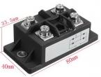
I go further, you need 4 diodes with a voltage of 600V or more, but 1000V is better. It is better to choose a larger current for diodes, say 150A will be just right. I'll turn to AliExpress for this matter. I found a suitable 150A 1600V diode bridge for reverse breakdown; such a good margin for reverse voltage will not be superfluous. 
The price for such a diode bridge is 770.33 rubles, here is the link for purchase. You also need a radiator to cool the diode bridge, there are no better ideas than a radiator from a PC processor, such a radiator can be bought at a flea market for 100-200R. And that’s 1000R for the rectifier
To operate a plasma cutter you need a compressor, well, that’s a done deal, it was assembled a long time ago. A compressor is good, but the air must be clean, free of oil and moisture. This means that you need to install a desiccant in front of the cutter, which again is better to order from China. I liked the AF2000-02 G1/4 filter for 442.20 rubles. 
The dehumidifier can withstand a pressure of 1.5 MPa, which is quite satisfactory. I also need a valve for control, I will use a valve like this, the price for it is 480 RUR. Here is the link
 Also, to connect to each other, you need fittings with a diameter of 1/4 inches
As an option, you can order 5 pieces for 276 rubles. link here
The next component of a plasma cutter, and perhaps the main one, is the torch itself. Such a burner costs a lot here, but in China they also ask 2400 RUR for it. 
From what the Chinese offer, this is the cheapest option. You can order one using this link. Also, to connect this sleeve you need a fitting, the same as I showed in the article about. I couldn’t find anything useful on the Internet, so I’ll have to order it from a turner. This is another 600-800 rubles
A few more components are needed for a complete set.
Several switches for controlling the power transformer and gas valve.  Such relays can be ordered from China for 100 rubles
Requires a 12V power supply to power the valve and relay  Such a power supply costs 232 rubles in China, you can buy it at this link. Connector for the control button on the holder.
This button turns on the transformer, opens the valve and turns on the oscillator. From China this costs 66 rubles, a mother-father set. Also, to ignite a plasma arc without contact, a high-voltage oscillator is needed  A ready-made module from China for power supply from an alternating voltage of 220V, the module costs 1,500 rubles, link
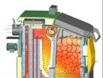
Factory plasma cutting machine. Our task: to make an analogue with your own hands
Making a functional plasma cutter with your own hands from a serial welding inverter is not as difficult as it might seem at first glance. In order to solve this problem, it is necessary to prepare all the structural elements of such a device:
- plasma cutter (also called a plasma torch);
- a welding inverter or transformer that will act as a source of electric current;
- a compressor, with the help of which a jet of air will be created, necessary for the formation and cooling of the plasma flow;
- cables and hoses for combining all structural elements of the device into one system.

Plasma cutters, including homemade ones, are successfully used to perform various jobs both in production and at home. Such a device is indispensable in situations where it is necessary to perform an accurate, thin and high-quality cut of metal workpieces. Some models of plasma cutters, due to their functionality, allow them to be used as a welding machine. This welding is performed in an argon shielding gas environment.

When choosing a power source to complete a homemade plasma torch, it is important to pay attention to the current strength that such a source can generate. Most often, an inverter is chosen for this, providing high stability to the plasma cutting process and allowing for more economical energy consumption. Differing from a welding transformer in its compact dimensions and light weight, the inverter is more convenient to use. The only disadvantage of using inverter plasma cutters is the difficulty of cutting too thick workpieces with their help.

When assembling a homemade device for performing plasma cutting, you can use ready-made diagrams that are easy to find on the Internet. In addition, there is a video on the Internet on how to make a plasma cutter with your own hands. When using a ready-made diagram when assembling such a device, it is very important to strictly adhere to it, and also pay special attention to the correspondence of the structural elements to each other.
Schemes of a plasma cutter using the example of the APR-91 device
When considering the electrical circuit diagram, we will use APR-91 as a donor.
Power section diagram (click to enlarge)
Plasma cutter control circuit (click to enlarge)
Oscillator circuit (click to enlarge)
Elements of a homemade plasma cutting machine
The first thing you need to find to make a homemade plasma cutter is a power source in which an electric current with the required characteristics will be generated. Most often they are used in this capacity, which is explained by a number of their advantages. Due to its technical characteristics, such equipment provides high stability of the generated voltage, which has a positive effect on the quality of cutting. Working with inverters is much more convenient, which is explained not only by their compact dimensions and low weight, but also by ease of setup and operation.

Due to their compactness and light weight, plasma cutters based on inverters can be used to perform work even in the most inaccessible places, which is impossible for bulky and heavy welding transformers. A huge advantage of inverter power supplies is that they have high efficiency. This makes them very energy efficient devices.
In some cases, a welding transformer can serve as a power source for a plasma cutter, but its use is fraught with significant energy consumption. It should also be taken into account that any welding transformer is characterized by large dimensions and significant weight.
The main element of the apparatus designed for cutting metal using a plasma jet is a plasma cutter. It is this element of equipment that ensures the quality of cutting, as well as the efficiency of its implementation.

To form an air flow that will be converted into a high-temperature plasma jet, a special compressor is used in the design of the plasma cutter. Electric current from the inverter and air flow from the compressor are supplied to the plasma cutter using a cable and hose package.
The central working element of the plasma cutter is the plasma torch, the design of which consists of the following elements:
- nozzles;
- the channel through which the air stream is supplied;
- electrode;
- an insulator that simultaneously performs a cooling function.
The first thing that needs to be done before manufacturing a plasma torch is to select the appropriate electrode for it. The most common materials used to make electrodes for plasma cutting are beryllium, thorium, zirconium and hafnium. When heated, refractory oxide films are formed on the surface of these materials, which prevent the active destruction of the electrodes.

Some of the above materials, when heated, can emit compounds hazardous to human health, which should be taken into account when choosing the type of electrode. Thus, when beryllium is used, radioactive oxides are formed, and thorium vapors, when combined with oxygen, form dangerous toxic substances. The completely safe material from which electrodes for plasmatrons are made is hafnium.
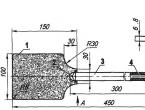
The nozzle is responsible for the formation of the plasma jet, thanks to which cutting is performed. Its manufacture should be given serious attention, since the quality of the work flow depends on the characteristics of this element.

The most optimal is a nozzle with a diameter of 30 mm. The accuracy and quality of the cut depends on the length of this element. However, you should also not make the nozzle too long, since this contributes to its destruction too quickly.
As mentioned above, the design of a plasma cutter necessarily includes a compressor that forms and supplies an air flow to the nozzle. The latter is necessary not only for the formation of a jet of high-temperature plasma, but also for cooling the elements of the apparatus. The use of compressed air as a working and cooling medium, as well as an inverter that generates an operating current of 200 A, allows you to effectively cut metal parts whose thickness does not exceed 50 mm.

In order to prepare the plasma cutting machine for operation, it is necessary to connect the plasma torch with an inverter and an air compressor. To solve this problem, a cable-hose package is used, which is used as follows.
- The cable through which electric current will be supplied connects the inverter and the plasma cutter electrode.
- A hose for supplying compressed air connects the compressor outlet and the plasmatron, in which a plasma jet will be formed from the incoming air flow.
Features of the plasma cutter
To make a plasma cutter using an inverter for its manufacture, you need to understand how such a device works.
After turning on the inverter, electric current from it begins to flow to the electrode, which leads to the ignition of an electric arc. The temperature of the arc burning between the working electrode and the metal tip of the nozzle is about 6000–8000 degrees. After the arc is ignited, compressed air is supplied to the nozzle chamber, which passes strictly through an electric discharge. The electric arc heats and ionizes the air flow passing through it. As a result, its volume increases hundreds of times, and it becomes capable of conducting electric current.
Using a plasma cutter nozzle, a plasma jet is formed from a conductive air flow, the temperature of which actively increases and can reach 25–30 thousand degrees. The speed of the plasma flow, due to which metal parts are cut, at the exit from the nozzle is about 2–3 meters per second. At the moment when the plasma jet comes into contact with the surface of the metal part, an electric current from the electrode begins to flow through it, and the initial arc goes out. The new arc that burns between the electrode and the workpiece is called cutting.
A characteristic feature of plasma cutting is that the metal being processed melts only in the place where it is exposed to the plasma flow. That is why it is very important to ensure that the plasma exposure spot is strictly in the center of the working electrode. If you neglect this requirement, you may encounter the fact that the air-plasma flow will be disrupted, which means the quality of the cut will deteriorate. In order to meet these important requirements, a special (tangential) principle of air supply to the nozzle is used.
It is also necessary to ensure that two plasma flows do not form at once instead of one. The occurrence of such a situation, which is caused by non-compliance with the modes and rules of the technological process, can provoke failure of the inverter.
An important parameter for plasma cutting is the air flow speed, which should not be too high. Good cutting quality and speed of execution are ensured by an air jet speed of 800 m/sec. In this case, the current supplied from the inverter apparatus should not exceed 250 A. When performing work in such modes, one should take into account the fact that in this case the air flow used to form the plasma flow will increase.
It’s not difficult to make a plasma cutter yourself if you study the necessary theoretical material, watch a training video and select all the necessary elements correctly. If you have such a device in your home workshop, assembled on the basis of a serial inverter, you can perform high-quality not only cutting, but also plasma welding with your own hands.
If you don’t have an inverter at your disposal, you can assemble a plasma cutter using a welding transformer, but then you’ll have to put up with its large dimensions. In addition, a plasma cutter made on the basis of a transformer will not have very good mobility, since it is difficult to move it from place to place.
A plasma cutting machine is a fairly popular piece of equipment that allows cutting any metals in many areas of production. Plasma cutters are used not only in enterprises. Recently, they have begun to appear in home workshops. But, since almost every workshop already has welding machines, it would be wiser not to buy a ready-made plasma cutter, but to make one from an inverter with your own hands.
In some cases, a plasma cutter is an indispensable tool for processing metal products, since the temperature of the plasma leaving its torch reaches 25-30 thousand degrees. Thanks to these characteristics, the scope of application of plasma cutters is quite extensive:
- production of various types of metal structures;
- laying of pipelines;
- fast cutting of any metals, including high-alloy heat-resistant steels containing titanium, nickel and molybdenum, the melting point of which is above 3000°C;
- shaped cutting of thin-sheet materials (conductive) due to high cutting precision.
In addition, plasma cutters (as an alternative to laser cutters) are used as part of automatic lines at large enterprises for cutting parts of various configurations from sheet materials.

It is necessary to distinguish between concepts such as plasma cutting and plasma welding. The latter is available only on expensive, professional equipment, the cost of which starts from 100 thousand rubles.
Inverter or transformer
There are various methods, as well as drawings and diagrams, according to which you can make a plasma cutter. For example, if it is made on the basis of a transformer welder, then the plasma cutter diagram provided below is suitable, which describes in detail what parts are needed to manufacture this module.
If you already have an inverter, then in order to convert it into a plasma cutter, you will need a little modification, namely adding an oscillator to the electrical circuit of the device. It is connected between the inverter and the plasma torch in two ways, as shown in the following figure.

The oscillator can be soldered independently according to the diagram provided below.
If you make a plasma cutter yourself, then choosing a transformer as a current source is not recommended for several reasons:
- the unit consumes a lot of electricity;
- The transformer is heavy and inconvenient to transport.
Despite this, the welding transformer also has positive qualities, for example, insensitivity to voltage changes. It can also cut thick metal.
But advantages of an inverter plasma cutting machine in front of the transformer unit there is:
- light weight;
- high efficiency (30% higher than that of a transformer);
- low electricity consumption;
- High-quality cutting thanks to a more stable arc.
Therefore, it is preferable to make a plasma cutter from a welding inverter than from a transformer.
Typical plasma cutter design
To assemble a device that will make air plasma cutting of metals possible, you will need to have the following components available.
- Power supply. Required to supply electric current to the burner electrode. The power source can be either a transformer (welding) that produces alternating current, or an inverter-type welding unit, the output of which is direct current. Based on the above, it is preferable to use an inverter, and with an argon welding function. In this case, it will have a connector for connecting the hose package and a place for connecting the gas hose, which will simplify the modification of the device.

- Plasma torch (cutter). It is a very important piece of equipment that has a complex design. In a plasma torch, a plasma jet is formed under the influence of an electric current and a directed air flow. If you decide to assemble a plasma cutter with your own hands, then it is better to purchase this element ready-made on Chinese websites.

- . Required for effective arc ignition and stabilization. As mentioned above, it is soldered according to a simple scheme. But if you are not strong in radio, then this module can be bought in China for 1,400 rubles.

- Designed to create an air flow entering the burner. Thanks to it, the plasma torch is cooled, the plasma temperature rises and the molten metal is blown away from the cut site on the workpiece. For homemade work, any compressor that is usually connected to a spray gun is suitable. But to remove water vapor from the air pumped by the compressor, you will need to install a filter drier.


- . Through it, current flows into the burner, facilitating the ignition of the electric arc and ionization of gases. Compressed air is also supplied to the burner through this hose. You can make a hose cable yourself by placing an electrical cable and an oxygen hose inside, for example, a water hose of a suitable diameter. But it’s still better to buy a ready-made hose package, which will have all the elements for connecting to the plasmatron and to the unit.

- Ground cable. It has a clamp at the end for attaching to the metal being processed.
Assembling the device
After all the necessary elements have been prepared, you can begin assembling the plasma cutter:
- connect a hose to the inverter through which air will be supplied from the compressor;
- connect the hose package and ground cable to the front side of the inverter;
- Connect the torch (plasma torch) to the hose package.
After assembling all the elements, you can begin equipment testing. To do this, connect the ground cable to the part or metal table on which it is placed. Turn on the compressor and wait until it pumps the required amount of air into the receiver. After the compressor automatically turns off, turn on the inverter. Bring the torch close to the metal and press the start button to create an electric arc between the torch electrode and the workpiece. Under the influence of oxygen, it will turn into a stream of plasma, and metal cutting will begin.
In order for a homemade plasma cutter from a welding inverter to work effectively and for a long time, you should listen to the advice of specialists related to the operation of the device.
- Recommended to have a certain number of gaskets which are used to connect hoses. Their presence should especially be checked when the unit has to be transported frequently. In some cases, the absence of the necessary gasket will make the device impossible to use.
- Because the cutter nozzle is exposed to high temperatures, it will wear out and fail over time. Therefore, you should worry about purchasing spare nozzles.
- When selecting components for a plasma cutter, you should consider how much power you want to get from the unit. First of all, this concerns the choice of a suitable inverter.
- When choosing an electrode for a burner, if you make it yourself, you need to give preference to a material such as hafnium. This material does not emit harmful substances during heating. But it is still strongly recommended to use ready-made cutters manufactured at the factory, in which all parameters for air flow swirl are observed. A homemade plasmatron does not guarantee high-quality cutting and quickly breaks down.
As for safety rules, work should be carried out in special clothing that protects against splashes of hot metal. You should also wear chameleon welding goggles to protect your eyes.
For cutting sheet metal, various mechanical devices are used, as well as electric welding or a gas cutter. But besides these methods, there is an effective way to cut metal - a plasma cutter. A factory-made installation is quite expensive, but it can be replaced with a homemade plasma cutter from a welding transformer.
The plasma cutting installation consists of the following parts:
- a plasma cutter or plasma torch that creates a plasma flow;
- welding transformer feeding the plasma torch;
- an oscillator or arc ignition unit that supplies high voltage at the moment the cut begins to form a plasma flow;
- a compressor to create air flow through the plasmatron;
- cables connecting the welding machine, plasma torch and the part being cut;
- hoses through which air or other gas and, if necessary, coolant are supplied.
The plasma head looks like a torch for a semi-automatic welding machine. Cables and hoses are also connected to it, but instead of a wire, a stream of plasma heated to 8000°C comes out of the nozzle.
How the device works
A plasma cutting installation is a kind of hybrid of electric welding and a gas cutter - the metal is melted by electricity, and the melt is blown out by a gas stream.
The main part of this device is the plasmatron. Inside it is a copper electrode with a rod made of a refractory metal - beryllium, thorium, zirconium or hafnium. At the end of the head there is a nozzle that forms a plasma flow. The nozzle is separated from the electrode by an insulator. The cut is made with reverse polarity - the electrode is the anode, and the nozzle and the metal being cut are the cathode.
The installation works as follows:
- when the unit is turned on, voltage from the welding transformer is supplied to the electrode and nozzle;
- with the help of an oscillator, an auxiliary electric arc occurs between these elements, limited by additional resistance;
- this arc heats the gas supplied to the plasmatron to 8000°C, which turns it into plasma and increases the pressure inside the head;
- a stream of air or other gas blows the plasma stream out of the nozzle;
- when leaving it, the plasma is compressed into a narrow beam, the speed of which can reach 1500 m/s, and the temperature 30000 ° C;
- when the plasma and the part being cut come into contact, the current begins to flow through the mass of the transformer;
- a current relay installed in series with the part turns off the oscillator and the pilot arc.
The thickness of the metal being cut depends on the current strength of the welding transformer.
Information! At a current of more than 100A, the plasmatron and the cable suitable for it need to be cooled with running water or other coolant.
Advantages and disadvantages of plasma cutting
Plasma metal cutting has advantages over other methods:
- the ability to cut any metals and alloys;
- high processing speed;
- clean cut line without sagging or drips of material;
- processing is carried out without heating the parts being cut;
- Flammable materials such as oxygen and natural gas cylinders are not used.

The disadvantages of plasma cutting are:
- complexity and high cost of installation;
- each operator with a plasma torch requires a separate transformer and control panel;
- cutting angle no more than 50°;
- a lot of noise when working.
What is a transformer for?
The power source for the plasma arc is a transformer with a rectifier. The current strength and metal cutting speed depend on its power, and the thickness of the material being cut depends on the output voltage.
You can connect a plasma cutting installation not only to a special transformer, but also to a welding machine that has the necessary characteristics.
It is impossible to do without such a device for several reasons:
- The transformer, by the very principle of its operation, limits the current in the secondary winding. When the plasma torch is powered directly from the mains, the device will operate in short circuit mode, so the cutting current and power consumption will exceed any permissible values.
- During operation, the welding machine acts as an isolating transformer. If you connect a plasma torch without it, the burner and the part will be energized, which is dangerous for human life.

Scheme
Like any electrical installation, a plasma cutting unit is assembled according to electrical diagrams.
Fundamental
This diagram shows all the elements of the installation, regardless of their location. The main purpose of this drawing is to show the connections between parts and make it easier to understand the operation of the installation.
The schematic diagram of the device shows the following elements:
- supply transformer with rectifier;
- oscillator;
- current relay;
- resistor that limits the pilot arc current;
- a contactor that turns off this arc;
- a starter that turns on the device;
- cutting button;
- compressor with control equipment.
Information! Power circuits can be depicted with thick lines.

Management
The control diagram shows all the buttons and controls that are located on the remote control or directly on the plasma torch:
- compressor activation buttons;
- air pressure regulator;
- in the presence of coolant, buttons and regulators of its flow;
- ammeter;
- voltmeter;
- water and air flow sensors;
- cutting control button (can be located on the plasma torch handle).

Information! All these elements are also shown on the schematic diagram.
Connections
The connection diagram shows the cables and hoses connecting all the elements to each other. It indicates the cross-section and length of the wires, as well as the connection location.

How to make a plasma cutter
The working tool of a plasma cutting installation is a cutter, or plasma torch. It creates a stream of air converted into plasma heated to 30,000°C, which cuts metal.
You can make it yourself. It is advisable to use a finished design as a sample. The plasma torch consists of several main elements:
- Central holder with replaceable electrode. With a cutting current of up to 100A and a metal thickness of up to 50 mm, the holder is made of copper rod; in more powerful devices there are channels inside for water cooling. To ignite the arc, the distance between the electrode and the nozzle must be 2 mm, therefore, to adjust the plasma torch, the central rod is made movable.
- Insulator between the central electrode and the outer casing. The part of the insulator closest to the nozzle wears out and is made of replaceable fluoroplastic.
- Outer casing with replaceable nozzle. Plasma is formed in the chamber between the electrode and the nozzle. When making a water-cooled device, there are channels for coolant inside the walls.
- Replaceable nozzles, cables - power and pilot arc, hoses.
Information! In water-cooled units, the power cable is not insulated and is located inside the hose that supplies water to the burner.
One way to make such a device is to make it from a TIG torch. It contains most of the necessary elements:
- tungsten electrode Ø4mm with adjustable position;
- terminal and cable for supplying current to it for welding;
- guide channels and a hose for supplying gas to the nozzle.
For modification you need:
- remove the thin-walled brass nozzle;
- screw on a cylindrical fluoroplastic insulating gasket with threads outside and inside the cylinder instead;
- Screw a brass body with a fastening for a copper nozzle onto the gasket on top;
- solder or clamp the pilot arc cable to the body;
- install a microswitch in the handle that turns on the cutting mode.

Replaceable attachments
Replaceable elements that wear out during operation are electrodes and nozzles:
- The electrode is made of copper with an insert of refractory metal - beryllium, thorium, zirconium and hafnium. The insert is located in the center, opposite the nozzle opening. An auxiliary short-term arc appears between the edge of the electrode and the nozzle, the working constant is between the insert and the part, therefore the insert is the most wearing element and is replaced along with the electrode.
- The nozzle produces a plasma jet formed by the electrode. The optimal nozzle size is 30mm, with a Ø2mm hole in the center. During operation, the plasma passing through it increases the diameter of the channel, which makes the gas flow wider and the cut less accurate. Therefore, the nozzle, like the electrode, should be changed periodically.
Gas selection
Despite the fact that any metal can be cut by an air flow created by a compressor, for each metal there is an optimal gas composition:
- copper, brass and titanium - nitrogen;
- aluminum – a mixture of nitrogen and hydrogen;
- high alloy steel - argon.

How to make a welding transformer
The plasma power source is a welding transformer. Like some other elements, you can make it yourself.
Required parameters
A transformer for plasma cutting differs from a conventional welder in the no-load voltage and is 220-250V. This is necessary to create and maintain an arc between the electrode and the part being cut. The power and current of the secondary winding depend on the expected metal thickness:
- 20A, 2.5 kW – 6 mm;
- 50A, 6kW – 12 mm;
- 80A, 10kW – 18-25 mm.
A power source is required with a “soft” characteristic; the operating voltage is 70V. A current of 5A is sufficient to operate the pilot arc. It is limited to a resistance of 30-50 Ohms, made of thick nichrome wire.
Information! It will not work to use a regular or inverter welder. These devices do not have enough voltage.
How to calculate
The calculation of the supply transformer comes down to determining the required sections of the magnetic circuit, the primary and secondary windings and the number of turns.
For a device designed to cut metal up to 12 mm at a current of 50A, an open circuit voltage of 200V and a mains voltage of 220V, these parameters are:
- magnetic core cross-section – 107 mm²
- primary winding – 225 turns of copper wire Ø4.7 mm;
- secondary winding – 205 turns of copper wire Ø5.04 mm².
Transformer manufacturing
Due to the fact that the transformer must have a “soft” characteristic, the coils are located separately from each other. When using an O-shaped core, they are located on different rods; on an W-shaped magnetic core, the windings are located along the middle part.
The coils are wound according to the calculated parameters on the frames of their electrical cardboard. The finished windings are wrapped with glass tape or keeper tape and coated with paint.

After winding the windings and assembling the magnetic circuit, a diode bridge of 4 diodes with radiators, assembled on a textolite platform, is attached and connected to the transformer. The assembled transformer is placed in the housing, and the outputs of the windings and diode bridge are connected to the terminals on the front panel. The connection is made according to the schematic diagram, taking into account the presence of ammeters, voltmeters, starters and other parts.
An oscillator connected in series with the welder has a high high frequency output voltage. Therefore, it is necessary to use high-frequency diodes in the rectifier or install a separate diode bridge, specifically for the pilot arc.
Other components
In addition to the plasma torch and transformer, there are other elements in the plasma cutting unit.
Compressor
The most common working gas is compressed air. It can be used when cutting almost all metals and alloys. The source of compressed air is a compressor. It can be used in any design, the minimum performance depends on the thickness of the metal:
- 16 mm – 140 l/min;
- 20 mm – 170l/min
- 30 mm – 190 l/min.
For more stable operation, a receiver with a capacity of 50 liters or more is required; the pressure created by the compressor must be more than 4.5 Bar.

Cables and hoses
To operate an air-cooled plasma cutter, the cable-hose package consists of the following elements:
- Power cable. Its cross section depends on the rated power of the device. With a current of 50A, sufficient to cut metal 10 mm thick and a vinyl-insulated wire, it is 6 mm². When using a cable in heat-resistant insulation, the cross-section is correspondingly reduced. You need 2 of these cables - one in a cable-hose package for the electrode and the second for ground.
- Wire for pilot arc. The cross-section is sufficiently 1.5 mm². According to the permissible heating, a thinner cable is allowed, but it has insufficient mechanical strength.
- Air supply hose. Inner diameter 10 mm.
- Wires for connecting a microswitch.

Oscillator
This is a device that increases the XX voltage of the welding transformer to a value that ensures the appearance of an electric arc without preliminary contact of the electrode and the ground.
Oscillators used in plasma cutting units are connected in series with a transformer and add 220V AC to the DC voltage, with a frequency of up to 250kHz and a voltage of up to 6kV.
This device itself does not produce a current that is dangerous to human health and, moreover, is not capable of creating an arc for welding or cutting metal. The main purpose of this device is to create a spark between the electrodes. This spark is a conductor and “paves the way” for the welding rectifier.
Advice! Instead of an oscillator, it is allowed to use an electronic car ignition.

Final assembly
Assembling a homemade plasma cutting unit involves connecting all elements with cables and hoses:
- cables for the electrode, ground and auxiliary arc are connected to the corresponding terminals on the welding transformer;
- the air hose is connected to the compressor receiver;
- the wires going to the microswitch on the handle are connected to the control circuit.
Examination
To check the assembled device, it is necessary to make a test cut of the metal:
- supply power to the transformer;
- after 10 minutes, turn off and check the windings for heating;
- if they are cold, reapply power;
- turn on the compressor;
- after filling the receiver, open the air valve and direct the air flow through the plasmatron;
- by pressing the microswitch button, light the auxiliary arc;
- If available, make a test cut of the metal.
After completing the tests, disconnect the device from the mains and again check all elements for heating.
Safety rules when working with a plasma cutter
The plasma cutting process, if operating rules are not followed, is dangerous to the health and life of people. The main harmful factors are:
- Splashes of molten metal. During the cut, the plasma stream melts the metal and blows it out of the part being cut. Contact of molten drops with flammable substances leads to their ignition, and contact with skin causes severe burns, up to IV degree (charring). For protection, it is necessary to direct the plasma flow away from people and flammable materials.
- Harmful gases and dust. During cutting, the metal not only melts, but also burns. The resulting smoke is harmful to health. In addition, contaminants on the surface of parts burn. Therefore, the workplace must be equipped with exhaust ventilation and work in a respirator.
- Bright light. During the operation of electric welding and cutting with plasma formed by an electric arc, in addition to visible light, ultraviolet radiation appears. This type of radiation causes burns to the retina of the eyes. For protection, the workplace is fenced with portable shields, and the cutter must use a protective shield.
- Temperature. After completion of work, the edges of the part remain heated to a high temperature for some time and touching them can lead to burns. To avoid such injuries, cut parts should only be touched with protective gloves or after sufficient time for the edges to cool.

Average cost of a transformer plasma cutter assembled by yourself
The cost of a homemade plasma cutter depends on the price of components. Ideally, such a device is assembled from various old junk and spare parts available in the workshop.
In any case, you should focus on the price of a store-bought plasma cutter, which depends on the thickness of the metal being cut, the availability of additional accessories, the manufacturer’s company and other factors.
The average cost of such devices depends on the thickness of the metal being cut:
- up to 30 mm – 150–300 thousand rubles;
- 25 mm – 81–220 thousand rubles;
- 17 mm – 45–270 thousand rubles;
- 12 mm – 32–230 thousand rubles;
- 10 mm – 25–20 thousand rubles;
- 6 mm – 15–20 thousand rubles.
Advice! Different manufacturers have different prices for components, so one way to save money is to purchase all the parts separately and assemble the device yourself from ready-made elements.
Parameters of plasma cutting of various metals
Despite the fact that all materials can be cut in one mode, to improve the quality of processing, different metals and alloys require different cutting modes, gas and equipment settings:
- Carbon steel – air, nitrogen, oxygen. Nozzle diameter 3 mm, cutting speed 0.3-5.5 mm/min.
- Stainless steel – air, nitrogen, hydrogen-argon mixture. Nozzle diameter 3 mm, cutting speed 0.3-5.5 mm/min.
- Aluminum - nitrogen, hydrogen-argon mixture. Nozzle diameter 2-3 mm, cutting speed 0.1-1.6 mm/min.
- Copper and alloys - air over 40 mm, nitrogen - 5-15 mm. Nozzle diameter 3-3.5 mm, cutting speed 0.4-3 mm/min
Information! The cutting speed depends on the installation current and the thickness of the part. In this case, it is important that the end of the arc “keeps up” with its beginning.
Plasma cutting of metal is a modern processing method. The presence of such a device, made from a welding transformer, in the workshop expands the capabilities of the master.