DIY decimeter antenna for T2. How to make a digital television antenna with your own hands for the garden and at home. Double or triple square for weaker signal

The era of digital signals has arrived. All broadcast television companies began to work in a new format. Analog TVs are reaching their end. They are still in working order and are found in almost every family.
In order for older models to successfully complete their service life, and for people to be able to use them when watching digital broadcasting, it is enough to connect the DVB-T set-top box to the TV receiver and pick up the TV wave signals with a special antenna.
Any home craftsman can not buy an antenna in a store, but make it with his own hands from available materials for watching digital TV programs at home or in the country. The two most accessible designs are described in this article.
A little theory
Operating principle of an antenna for digital packet television
Any television signal propagates in space from the emitters of the transmitting television tower to the TV antenna by an electromagnetic wave of a sinusoidal shape with a high frequency, measured in megahertz.

When an electromagnetic wave passes through the surface of the receiving beams of the antenna, a voltage V is induced in it. Each half-wave of a sinusoid forms a potential difference with its own sign.
Under the influence of an induced voltage applied to a closed receiving circuit of the input signal with resistance R, an electric current flows in the latter. It is amplified and processed by the digital TV circuit and output to the screen and speakers as image and sound.

For analog models of TV receivers, an intermediate link works between the antenna and the TV - a DVB-T set-top box, which decodes digital information of an electromagnetic wave into a normal form.
Vertical and horizontal polarization of digital TV signal
In television broadcasting, state standards require electromagnetic waves to be emitted in only two planes:
- horizontal.

In this way, transmitters send emitting signals.
And users simply need to rotate the receiving antenna in the desired plane to maximize the power potential.
Requirements for a digital packet television antenna
TV transmitters propagate their signal waves over short distances, limited by the line of sight from the top point of the TV tower emitter. Their range rarely exceeds 60 km.
For such distances, it is enough to provide a small power of the emitted TV signal. But, the strength of the electromagnetic wave at the end of the coverage area should form a normal voltage level at the receiving end.
A small potential difference, measured in fractions of a volt, is induced at the antenna. It creates currents with small amplitudes. This imposes high technical requirements on the installation and quality of manufacturing of all parts of digital reception devices.
The antenna design should be:
- manufactured carefully, with a good degree of accuracy, eliminating loss of electrical signal power;
- directed strictly along the axis of the electromagnetic wave coming from the transmitting center;
- oriented according to the type of polarization;
- protected from extraneous interference signals of the same frequency coming from any sources: generators, radio transmitters, electric motors and other similar devices.
How to find out the initial data for calculating an antenna
The main parameter influencing the quality of the received digital signal, as can be seen from the explanatory first figure, is the length of the electromagnetic wave of radiation. Under it, symmetrical arms of vibrators of various shapes are created, and the overall dimensions of the antenna are determined.
The wavelength λ in centimeters can be easily calculated using a simplified formula: λ=300/F. It is enough just to find the frequency of the received signal F in megahertz.
To do this, we will use a Google search and ask it for a list of regional TV communication points for our area.
As an example, a fragment of a data table for the Vitebsk region is shown with the transmitting center in Ushachi highlighted in red.

Its wave frequency is 626 megahertz, and its polarization type is horizontal. This data is quite sufficient.
We carry out the calculation: 300/626=0.48 m. This is the length of the electromagnetic wave for the antenna being created.
We divide it in half and get 24 cm - the desired half-wave length.
The tension reaches its maximum value in the middle of this section - 12 cm. It is also called amplitude. The whip antenna is made to this size. It is usually expressed by the formula λ/4, where λ is the electromagnetic wavelength.
The simplest TV antenna for digital television
It will require a piece of coaxial cable with a characteristic impedance of 75 Ohms and a plug for connecting the antenna. I managed to find a ready-made two-meter piece in the old stock.

I cut off the outer shell from the free end with a regular knife. I take the length with a small margin: when setting up it is always easier to bite off a small piece.

Then I remove the shielding layer from this section of the cable.


The work is done. All that remains is to insert the plug socket into the connector on the TV signal set-top box and direct the bare wire of the inner core across the incoming electromagnetic wave, taking into account horizontal polarization.

The antenna should be placed directly on the window sill or secured to the glass, for example, with a piece of tape, or tied to the blind mount. Reflected signals and interference can be shielded with a strip of foil located a short distance from the central core.
Such a design can be done in literally ten minutes and does not require any special material costs. It's worth trying. But, it is capable of working in an area of reliable signal reception. My building is screened by a mountain and a multi-story building. The transmitting television tower is located at a distance of 25 km. Under these conditions, the digital electromagnetic wave is reflected many times and is poorly received. I had to look for another technical solution.
And for you on the topic of this design, I suggest you watch the video by the owner of Edokoff “How to make an antenna for digital TV”
Kharchenko antenna at 626 MHz
To receive analogue television signals of various wave frequencies, the design of a zigzag broadband antenna, which does not require complex manufacturing, worked well for me before.
I immediately remembered one of their effective varieties - the Kharchenko antenna. I decided to use its design for digital reception. I made the vibrators from a flat copper bar, but it’s quite possible to get by with round wire. This will make it easier to bend and straighten the ends.

How to determine the dimensions of a specific antenna
Online calculator
Let's use the all-knowing Google search. We write on the command line: “Calculation of the Kharchenko antenna” and press Enter.

We choose any site you like and perform online calculations. I went into the first one that opened. This is what he calculated for me.

I presented all his data with a picture indicating the size of the Kharchenko antenna.

Manufacturing of antenna design parts
I took the information provided as a basis, but did not accurately maintain all the dimensions. I know from previous practice that the antenna works well in the broadband wavelength range. Therefore, the dimensions of the parts were simply slightly increased. The half-wave of each harmonic of the sine wave of the electromagnetic TV signal will fit into the arm of each vibrator and will be received by it.
Based on the selected data, I made blanks for the antenna.

Vibrator design features
The connection of the ends of the figure eight busbar is created in the center at the bending stage. I soldered them with a soldering iron.

I created it according to the “Moment” principle, made it with my own hands from old transformers, and has been working for two decades. I even soldered 2.5 square copper wire with it in thirty-degree frost. Works with transistors and microcircuits without burning them out.
In the near future I plan to describe its design in a separate article on the website for those who also want to make it themselves. Follow publications, subscribe to notifications.
Connecting the antenna cable to the vibrator
I simply soldered the copper core and braid to the metal of the figure eight from different sides in its center.

The cable was tied to a copper bar, bent into a loop in the shape of a semi-square vibrator. This method matches the resistance of the cable and antenna.
Screening grid design
In fact, the Kharchenko antenna often works normally without signal shielding, but I decided to show its manufacture. For the base I took a wooden block. I did not paint or varnish: the structure will be used indoors.
In the back side of the block I drilled holes for attaching the screen wires and inserted them, and then wedged them.

The result was a screen for the Kharchenko antenna. In principle, it can be made of a different design: cut from a piece of frontal armor of a tank or cut from food foil - it will work approximately the same.

On the back side of the bar I secured the vibrator structure with a cable.

The antenna is ready. All that remains is to install it on a window to work in vertical polarization.

When a television receiver is located at a great distance from the transmitting generator, the power of its signal gradually weakens. It can be increased by special electronic devices - amplifiers.
You just need to clearly see the difference between the signals received by the antenna, which can be:
- simply weakened;
- contain high-frequency interference that distorts the shape of the digital sinusoid into the shape of some kind of “doodleball”.
In both cases, the amplifier will fulfill its role and increase the power. Moreover, the TV will clearly perceive and display a weakened signal, but with an amplified signal, playback problems will arise.
The waves are designed to eliminate such interference:
- high-pressure filters;
- screens.
They must be measured with an oscilloscope, and the methods of using various designs must be analyzed individually in each specific case. The antenna is not to blame here.
Today, more and more people are switching to T2 digital television - there are more channels and better picture quality. To do this, city residents install an antenna at home. But how to solve the problem for those who live outside the city or rent an apartment? It’s quite simple - make your own antenna for T2; it will be a profitable alternative to a factory antenna.
Made with your own hands, such a digital antenna has certain advantages. Firstly, this is a very cheap product. Secondly, it often has a higher gain than an antenna from a store.
Since the digital television broadcast signal propagates in the UHF wavelength range, any UHF antenna is suitable in our case.
Copper wire
The wire model will be a simple solution for those who need a regular indoor antenna to watch TV channels. To do it, no special knowledge is required; even a schoolboy can handle it.To make such a simple structure, you only need to take copper wire 70–90 cm long and 2–3 mm thick. At one end we attach it to the battery, and at the other we insert it into the antenna connector of the TV.
DIY antenna for T2 from beer cans
This method is the most common for homemade antenna assembly. This will take available materials and no more than an hour of work time.
Step-by-step description of the work:
1 . We attach the cans to the beam or pipe at a distance of 6–7 cm.
2 . We fasten the screws to the cans.
3 . We take a coaxial cable, strip the ends, and insert it into the screws.
4 . To ensure that the work of the homemade product is not affected by rain and snow, it is recommended to take a plastic bottle and make a protection out of it.


DIY antenna 8 for digital TV: manufacturing technology
The so-called “figure eight” was used as a basis, only without a reflector. The antenna sheet can be made of any conductive material with a suitable cross-section - for example, copper or aluminum wire 1-5 mm thick, tube, strip, busbar, corner, profile - with top sides of 14 cm, sides of 13.
The approximate dimensions are given here; some deviations may be allowed - as long as the DIY digital antenna works well.
You need to measure a piece with a total length of 112 cm, then bend the wire.
For the first part – 13 cm + 1 cm under the loop, for the next 6 sides – 14 cm, for the last side – 13 cm + 1 cm.

At both ends you should strip 1.5–2 cm, twist two loops one behind the other, and then solder the joint. This will result in one cable connection contact. After 2 cm - the second one. It doesn’t matter where the central core will be soldered and where the braid will be soldered.

We measure the required cable length.

We strip the cable from the antenna side - 2 cm, to the plug - 1 cm.

After sealing, the soldering areas should be filled with glue from a gun.

The result was a homemade antenna for T2, which can be easily attached anywhere - on the curtain rod or on the curtain.
Buying a good antenna for your dacha is not always advisable. Especially if she is visited from time to time. The point is not so much the cost, but the fact that after a while it may not be there. Therefore, many people prefer to make an antenna for their dacha themselves. Costs are minimal, quality is good. And the most important point is that a TV antenna can be made with your own hands in half an hour or an hour and then, if necessary, can be easily repeated...
Digital television in the DVB-T2 format is transmitted in the UHF range, and there is either a digital signal or it is not. If the signal is received, the picture is of good quality. Due to this. Any decimeter antenna is suitable for receiving digital television. Many radio amateurs are familiar with the TV antenna, which is called “zigzag” or “figure eight”. This DIY TV antenna can be assembled literally in a matter of minutes.
To reduce the amount of interference, a reflector is placed behind the antenna. The distance between the antenna and the reflector is selected experimentally - according to the “purity” of the picture  You can attach foil to the glass and get a good signal...
  Copper tube or wire is the best option; it bends well and is easy to bend.
It is very simple to make; the material is any conductive metal: tube, rod, wire, strip, corner. Despite its simplicity, she accepts it well. It looks like two squares (rhombuses) connected to each other. In the original, there is a reflector behind the square for more reliable signal reception. But it is more needed for analog signals. To receive digital television, you can do without it or install it later if the reception is too weak.
Materials
Copper or aluminum wire with a diameter of 2-5 mm is optimal for this homemade TV antenna. In this case, everything can be done in literally an hour. You can also use a tube, corner, strip of copper or aluminum, but you will need some kind of device to bend the frames to the desired shape. The wire can be bent with a hammer, securing it in a vice.

You will also need a coaxial antenna cable of the required length, a plug suitable for the connector on your TV, and some kind of mount for the antenna itself. The cable can be taken with a resistance of 75 Ohms and 50 Ohms (the second option is worse). If you are making a TV antenna with your own hands for installation outdoors, pay attention to the quality of the insulation.
The mounting depends on where you are going to hang your homemade antenna for digital television. On the upper floors, you can try to use it as a home decoration and hang it on curtains. Then you need large pins. At the dacha or if you take a homemade TV antenna to the roof, you will need to attach it to a pole. For this case, look for suitable fasteners. To work, you will also need a soldering iron, sandpaper and/or file, and a needle file.
Do you need a calculation?
To receive a digital signal, there is no need to count the wavelength. It is simply advisable to make the antenna more broadband in order to receive as many signals as possible. To do this, some changes were made to the original design (pictured above) (further in the text).
If you wish, you can make a calculation. To do this, you need to find out what wavelength the signal is broadcast on, divide by 4 and get the required side of the square. To obtain the required distance between the two parts of the antenna, make the outer sides of the diamonds slightly longer and the inner ones shorter.

Drawing of a figure-of-eight antenna for receiving digital TV
- The length of the “inner” side of the rectangle (B2) is 13 cm,
- “external” (B1) - 14 cm.
Due to the difference in lengths, a distance is formed between the squares (they should not be connected). The two extreme sections are made 1 cm longer so that you can fold the loop to which the coaxial antenna cable is soldered.
Making a frame
If you count all the lengths, you get 112 cm. Cut off the wire or whatever material you have, take pliers and a ruler, and start bending. The angles should be 90° or so. You can make a little mistake with the lengths of the sides - this is not fatal. It turns out like this:
- The first section is 13 cm + 1 cm per loop. The loop can be bent immediately.
- Two sections of 14 cm each.
- Two 13 cm each, but with a turn in the opposite direction - this is the point of inflection onto the second square.
- Again two 14 cm each.
- The last one is 13 cm + 1 cm per loop.
The antenna frame itself is ready. If everything was done correctly, there will be a distance of 1.5-2 cm between the two halves in the middle. There may be small discrepancies. Next, we clean the loops and the bend point to bare metal (treat it with fine-grain sandpaper), and tin it. Connect the two loops and crimp them with pliers to hold them tightly.

Cable preparation
We take the antenna cable and carefully clean it. How to do this is shown in the step-by-step photo. You need to strip the cable on both sides. One edge will be attached to the antenna. Here we strip it so that the wire sticks out 2 cm. If it turns out more, the excess (later) can be cut off. Twist the screen (foil) and braid into a bundle. It turned out to be two conductors. One is the central monocore of the cable, the second is twisted from many braided wires. Both are needed and need to be tinned.

We solder the plug to the second edge. A length of 1 cm or so is sufficient here. Also form two conductors and tin them.
Wipe the plug in the places where we will solder with alcohol or solvent, and clean it with emery (you can use a needle file). Place the plastic part of the plug on the cable, now you can start soldering. We solder a monocore to the central output of the plug, and a multicore twist to the side output. The last thing is to crimp the grip around the insulation.

Then you can simply screw on the plastic tip and fill it with glue or non-conductive sealant (this is important). While the glue/sealant has not hardened, quickly assemble the plug (screw on the plastic part) and remove the excess compound. So the plug will be almost eternal.
DIY DVB-T2 TV antenna: assembly
Now all that remains is to connect the cable and the frame. Since we were not tied to a specific channel, we will solder the cable to the middle point. This will increase the broadband of the antenna - more channels will be received. Therefore, we solder the second cut end of the cable to the two sides in the middle (those that were stripped and tinned). Another difference from the “original version” is that the cable does not need to be routed around the frame and soldered at the bottom. This will also expand the reception range.
The assembled antenna can be checked. If the reception is normal, you can finish the assembly - fill the solder joints with sealant. If the reception is poor, try first to find a place where the fishing is better. If there are no positive changes, you can try replacing the cable. To simplify the experiment, you can use regular telephone noodles. It costs a penny. Solder the plug and frame to it. Try it with her. If it catches better, it’s a bad cable. In principle, you can work on “noodles”, but not for long - they will quickly become unusable. It is better, of course, to install a normal antenna cable.

To protect the junction of the cable and the antenna frame from atmospheric influences, the soldering points can be wrapped with regular electrical tape. But this method is unreliable. If you remember, you can put on several heat-shrinkable tubes before soldering to insulate them. But the most reliable way is to fill everything with glue or sealant (they should not conduct current). As a “case” you can use lids for 5-6 liter water cylinders, ordinary plastic lids for jars, etc. We make indentations in the right places - so that the frame “sits” in them, do not forget about the cable outlet. Fill it with a sealing compound and wait until it sets. That's it, your DIY TV antenna for receiving digital television is ready.
Homemade double and triple square antenna
This is a narrowband antenna, which is used if you need to receive a weak signal. It can even help if a weaker signal is “clogged” by a stronger one. The only drawback is that you need precise orientation to the source. The same design can be made to receive digital television.
 You can also make five frames - for a more confident reception
  It is not advisable to paint or varnish - reception deteriorates. This is only possible in close proximity to the transmitter
The advantages of this design are that reception will be reliable even at a considerable distance from the repeater. You just need to specifically find out the broadcast frequency, maintain the dimensions of the frames and the matching device.
Construction and materials
It is made from tubes or wire:
- 1-5 TV channel MV range - tubes (copper, brass, aluminum) with a diameter of 10-20 mm;
- 6-12 TV channel MV range - tubes (copper, brass, aluminum) 8-15 mm;
- UHF range - copper or brass wire with a diameter of 3-6 mm.
The double square antenna consists of two frames connected by two arrows - upper and lower. The smaller frame is a vibrator, the larger one is a reflector. An antenna consisting of three frames gives a higher gain. The third, smallest square is called the director.

The upper boom connects the middle of the frames and can be made of metal. The lower one is made of insulating material (textolite, gettinax, wooden plank). The frames must be installed so that their centers (the points of intersection of the diagonals) are on the same straight line. And this straight line should be directed towards the transmitter.
The active frame - the vibrator - has an open circuit. Its ends are screwed to a textolite plate measuring 30*60 mm. If the frames are made from a tube, the edges are flattened, holes are made in them and the lower arrow is attached through them.
The mast for this antenna must be wooden. At least the upper part of it. Moreover, the wooden part should start at a distance of at least 1.5 meters from the level of the antenna frames.
Dimensions
All dimensions for making this TV antenna with your own hands are given in the tables. The first table is for the meter range, the second is for the decimeter range.

In three-frame antennas, the distance between the ends of the vibrator (middle) frame is larger - 50 mm. Other sizes are given in the tables.

Connecting an active frame (vibrator) via a short-circuited cable
Since the frame is a symmetrical device, and it must be connected to an asymmetrical coaxial antenna cable, a matching device is required. In this case, a balancing short-circuited loop is usually used. It is made from pieces of antenna cable. The right segment is called the “loop”, the left one is called the “feeder”. A cable is attached to the junction of the feeder and the cable, which goes to the TV. The length of the segments is selected based on the wavelength of the received signal (see table).

A short piece of wire (loop) is cut at one end by removing the aluminum screen and twisting the braid into a tight bundle. Its central conductor can be cut down to insulation, since it does not matter. The feeder is also cut. Here, too, the aluminum screen is removed and the braid is twisted into a bundle, but the central conductor remains.
Further assembly proceeds like this:
- The braid of the cable and the central conductor of the feeder are soldered to the left end of the active frame (vibrator).
- The feeder braid is soldered to the right end of the vibrator.
- The lower end of the cable (braid) is connected to the feeder braid using a rigid metal jumper (you can use wire, just make sure there is good contact with the braid). In addition to the electrical connection, it also sets the distance between sections of the matching device. Instead of a metal jumper, you can twist the braid of the lower part of the cable into a bundle (remove the insulation in this area, remove the screen, roll it into a bundle). To ensure good contact, solder the bundles together with low-melting solder.
- The cable pieces must be parallel. The distance between them is about 50 mm (some deviations are possible). To fix the distance, clamps made of dielectric material are used. You can also attach a matching device to a textolite plate, for example.
- The cable going to the TV is soldered to the bottom of the feeder. Braid is connected to braid, center conductor to center conductor. To reduce the number of connections, the feeder and cable to the TV can be made single. Only in the place where the feeder should end must the insulation be removed so that the jumper can be installed.
This matching device allows you to get rid of noise, blurred contours, and a second blurry image. It is especially useful at a great distance from the transmitter, when the signal is clogged with interference.
Another variation of the triple square
In order not to connect a short-circuited loop, the triple square antenna vibrator is made elongated. In this case, you can connect the cable directly to the frame as shown in the figure. Only the height at which the antenna wire is soldered is determined in each case individually. After the antenna is assembled, “testing” is carried out. The cable is connected to the TV, the central conductor and braid are moved up/down, achieving a better image. In the position where the picture will be clearest, the antenna cable branches are soldered, and the soldering points are insulated. The position can be any - from the bottom jumper to the transition point to the frame.

Sometimes one antenna does not give the desired effect. The signal turns out to be a weak image - black and white. In this case, the standard solution is to install a television signal amplifier.
The simplest antenna for a summer residence is made from metal cans
To make this television antenna, in addition to the cable, you will only need two aluminum or tin cans and a piece of wooden plank or plastic pipe. Cans must be metal. You can take aluminum beer beers, or you can take tin ones. The main condition is that the walls are smooth (not ribbed).

The jars are washed and dried. The end of the coaxial wire is cut - by twisting the braided strands and clearing the central core of insulation, two conductors are obtained. They are attached to banks. If you know how, you can solder it. No - take two small self-tapping screws with flat heads (you can use “fleas” for drywall), twist a loop at the ends of the conductors, thread a self-tapping screw with a washer installed on it through it, and screw it to the can. Just before this you need to clean the metal of the can by removing the deposits using fine-grain sandpaper.

The cans are secured to the bar. The distance between them is selected individually - according to the best picture. You shouldn’t hope for a miracle - there will be one or two channels in normal quality, or maybe not... It depends on the position of the repeater, the “cleanliness” of the corridor, how correctly the antenna is oriented... But as a way out in an emergency, this is an excellent option.
A simple Wi-Fi antenna made from a metal can
An antenna for receiving a Wi-Fi signal can also be made from improvised means - from a tin can. This DIY TV antenna can be assembled in half an hour. This is if you do everything slowly. The jar should be made of metal, with smooth walls. Tall and narrow canning jars work great. If you will be installing a homemade antenna on the street, find a jar with a plastic lid (as in the photo). The cable is an antenna, coaxial, with a resistance of 75 Ohms.

In addition to the can and cable, you will also need:
- RF-N connector;
- a piece of copper or brass wire with a diameter of 2 mm and a length of 40 mm;
- cable with a socket suitable for a Wi-Fi card or adapter.
Wi-Fi transmitters operate at a frequency of 2.4 GHz with a wavelength of 124 mm. So, it is advisable to choose a jar such that its height is at least 3/4 of the wavelength. For this case, it is better that it be more than 93 mm. The diameter of the can should be as close as possible to half the wavelength - 62 mm for a given channel. There may be some deviations, but the closer to the ideal, the better.
Dimensions and assembly
When assembling, a hole is made in the jar. It must be placed strictly at the desired point. Then the signal will be amplified several times. It depends on the diameter of the selected jar. All parameters are shown in the table. You measure the exact diameter of your can, find the right stitch, and have all the right dimensions.

| D - diameter | Lower limit of attenuation | Upper limit of attenuation | Lg | 1/4 Lg | 3/4 Lg |
|---|---|---|---|---|---|
| 73 mm | 2407.236 | 3144.522 | 752.281 | 188.070 | 564.211 |
| 74 mm | 2374.706 | 3102.028 | 534.688 | 133.672 | 401.016 |
| 75 mm | 2343.043 | 3060.668 | 440.231 | 110.057 | 330.173 |
| 76 mm | 2312.214 | 3020.396 | 384.708 | 96.177 | 288.531 |
| 77 mm | 2282.185 | 2981.170 | 347.276 | 86.819 | 260.457 |
| 78 mm | 2252.926 | 2942.950 | 319.958 | 79.989 | 239.968 |
| 79 mm | 2224.408 | 2905.697 | 298.955 | 74.738 | 224.216 |
| 80 mm | 2196.603 | 2869.376 | 282.204 | 070.551 | 211.653 |
| 81 mm | 2169.485 | 2833.952 | 268.471 | 67.117 | 201.353 |
| 82 mm | 2143.027 | 2799.391 | 256.972 | 64.243 | 192.729 |
| 83 mm | 2117.208 | 2765.664 | 247.178 | 61.794 | 185.383 |
| 84 mm | 2092.003 | 2732.739 | 238.719 | 59.679 | 179.039 |
| 85 mm | 2067.391 | 2700.589 | 231.329 | 57.832 | 173.497 |
| 86 mm | 2043.352 | 2669.187 | 224.810 | 56.202 | 168.607 |
| 87 mm | 2019.865 | 2638.507 | 219.010 | 54.752 | 164.258 |
| 88 mm | 1996.912 | 2608.524 | 213.813 | 53.453 | 160.360 |
| 89 mm | 1974.475 | 2579.214 | 209.126 | 52.281 | 156.845 |
| 90 mm | 1952.536 | 2550.556 | 204.876 | 51.219 | 153.657 |
| 91 mm | 1931.080 | 2522.528 | 201.002 | 50.250 | 150.751 |
| 92 mm | 1910.090 | 2495.110 | 197.456 | 49.364 | 148.092 |
| 93 mm | 1889.551 | 2468.280 | 194.196 | 48.549 | 145.647 |
| 94 mm | 1869.449 | 2442.022 | 191.188 | 47.797 | 143.391 |
| 95 mm | 1849.771 | 2416.317 | 188.405 | 47.101 | 141.304 |
| 96 mm | 1830.502 | 2391.147 | 185.821 | 46.455 | 139.365 |
| 97 mm | 1811.631 | 2366.496 | 183.415 | 45.853 | 137.561 |
| 98 mm | 1793.145 | 2342.348 | 181.169 | 45.292 | 135.877 |
| 99 mm | 1775.033 | 2318.688 | 179.068 | 44.767 | 134.301 |
The procedure is as follows:

You can do without an RF connector, but with it everything is much simpler - it’s easier to position the emitter vertically upward, connect the cable going to the router or Wi-Fi card.
If you live in the city, then you don’t necessarily need to have a large and bulky TV antenna, much less throw it on the roof and pull the cable. Digital television channels of the DVB-T2 standard can be perfectly received in the room, since the power of the transmitting towers is quite enough for reliable reception. I'll show you how to make a miniature home antenna of the Biquadrat type in 15 minutes. I also call it the Kharchenko antenna. This master class will save you from buying expensive Chinese analogues.
Typically, such structures are calculated using 1/4 wavelength. Such an antenna will receive all channels well even outside the city at a considerable distance, but at home (in the city) its size may seem a little large. And in fact, such sensitivity will be of no use. You can reduce all dimensions by half and take 1/8 of the wavelength as a calculation. The current antenna will be very tiny, but with sufficient sensitivity.
What do you need

Home antenna circuit for digital television The antenna circuit itself. This is perhaps the simplest and most common option, and we will make it even smaller.

We take the wire and, without removing the insulation, bend two identical squares with sides 67 mm with pliers.

We solder the joined ends and peel off a little insulation from the middle and tin.

Then, solder the socket on small wires. Using a utility knife, make cuts in the lid for the shoulders of the vibrators.

Fill everything with hot glue.

In the second cover we drill a hole for the socket and also glue it in with hot glue. We connect the covers and solder them with a soldering iron to make one whole. The antenna is ready.

Everything fits in the palm of your hand, so with the question “Where should I place it?” There shouldn't be any problems.
Result
We connect and direct to the tower.

I will compare the antenna with the same one, only full-size at 1/4 wavelength.

The level sensor will be a Chinese set-top box for receiving digital television.
Result:
- Classic Kharchenko antenna 1/4 wavelength, the set-top box issued - 40% sensitivity.
- Our reduced 1/8 wavelength version is 22% .
- And for comparison, let’s plug in a regular piece of wire - 1% .
Conclusion: When the size was halved, the sensitivity dropped by about the same amount. But, as you can see from the results, there is no comparison with a piece of wire.
At home, the antenna performed excellently. All channels are caught and received steadily, just like the full-size version. I recommend it for repetition.
A simple DIY antenna for Digital TV
zen.yandex.ru/media/komp/
Now probably only the lazy don’t know that there are plans to switch to broadcasting a television signal in the DVB-T2 digital standard. You can talk a lot about the benefits and harms of watching TV in general, but that’s not what we’re talking about today. I want to talk about how to make an antenna at home using available and inexpensive materials to receive a television signal in the digital standard.

Antenna installation option
1. You can choose almost any conductive material as a material, but it is most convenient to work with copper wire with a diameter of 3-4 mm. It is necessary to measure a piece of copper wire 112 cm long. Then you need to bend 2 squares from this piece of wire according to the following pattern:
– side No. 1 = 13 cm + 1 cm loop (pictured);
– sides No. 2 and 3 = 14 cm;
– side No. 4 and 5 = 13 cm;
– side No. 6 and 7 = 14 cm;
– side No. 8 = 13 cm + 1 cm loop (same as side No. 1).

Side No. 1 is 13 cm long with a loop at the end of the wire.
At the end of the wire we bend one loop at a time, having first stripped the wire a little, and then we connect the loops and crimp the resulting connection with pliers. One of the cores of the coaxial cable will be connected here. The distance between the inner corners of the squares should be about 2 cm.

This is how the ends of the wire are connected
Now you need to take a piece of coaxial cable of the required length and strip both ends. Then solder one end of the cable to the antenna, and the other to the plug.


The soldering area is filled with hot glue
The antenna is now ready for installation!

Ready antenna
If you don’t like the option of soldering the plug, then you can use connectors without soldering - F-connector rg-6:

How to easily make an antenna for digital TV in 5 minutes that picks up 20 channels and 3 radios
zen.yandex.ru/samodelka/
From January 2019 Analogue television will be switched off throughout Russia. If in cities with a population of more than 100 thousand people the analog signal will still spread, then in small settlements it will disappear completely.

If the TV does not receive digital channels, you will additionally need a DVB-T2 digital set-top box. Prices for consoles start from 700 rubles.

2 is currently broadcast throughout Russia 0 digital TV channels and 3 radio channels.
To receive digital channels you will also need an antenna connected to your TV or set-top box.
Nowadays you can often find advertisements in stores on the couch and on the Internet. miracle antennas, which connect to TV and pick up a digital signal in the most remote places, not saying a word about digital set-top boxes, without which there is nothing won't work. Moreover, they promise to receive more than 50 channels, which is basically impossible.
Elderly people most often fall for scammers who post several thousand rubles and are disappointed in the purchase.

In fact, you don’t need any unique antennas; a regular UHF television antenna will do.
Moreover, such an antenna can be made independently in just a few minutes, without spending a penny.
To do this you will need a small piece of coaxial cable. RG-6.

1 way
We connect the plug to the cable and retreat a couple of centimeters. Then we make a cut, remove the insulation and braid. We bend the inner part. The length of the curved part of the antenna should be 12-14 centimeters.

Such an antenna can be connected directly to a TV or set-top box if you are in conditions of good signal reception. Or use a coaxial cable to take it outside.

Method 2
We remove the external and internal insulation from the cable from 5-6 centimeters from the edge, without touching the braid. Next, we retreat 21-23 centimeters and remove the outer insulation and braiding at a distance of 1.5-2 centimeters. Then again we retreat 21-23 centimeters and in a segment of 1 centimeter we remove only the outer insulation without touching the braid.

Bend the cable into a circle and twist the edge of the cable with the section where the braid was left.

We get a simple antenna for reliable reception of all digital channels.
Good afternoon, dear readers. I haven’t written on the blog for a long time, due to the May holidays and a lot of work. But I managed to make one craft, very simple and useful - an antenna for digital TV with my own hands. At the same time, I’ll tell you, everything is quite simple.
Of course, cases are different, but before making this antenna, think: do you need it or not. This is what I'm getting at: nowadays it's easier to buy a digital antenna than to make it. If you just want to watch digital TV at home, constantly and preferably without interruptions, or the tower is far from your home, then it is better to seek advice and buy a good antenna in a store.
You need to understand that if you are making an antenna for the first time, you have little experience in electronics, or maybe none at all, then no one will be responsible for the fact that the antenna either will not work at all, or will stop working, and so on.
Personally, I don’t understand much about electronics, but I test what I do in practice and try to understand it as much as possible. The antenna samples presented below are quite simple and easy to manufacture.
Of course, if you need an antenna for a dacha where you rarely go, then a homemade antenna for digital TV with your own hands is perfect. I won’t bore you with calculations and various terms, I’ll just show and tell you, and you choose and try.
Write comments after the article, leave your opinion and, if there are errors, tell everyone about them.
I'll start with this antenna, since I made it myself for the first time. It seemed to me not difficult and at the same time quite powerful. Other sites said it was homemade. But I made it for my mother-in-law, in the village, where it was about 80 km from the broadcast tower to the antenna.
Butterfly antenna
My mother-in-law has been using it for more than two years now and there are practically no problems. Such an antenna is no different from a regular decimeter antenna. It is easier to convert a simple array-type antenna, which can be bought at a low price in a retail chain, into a digital one that will receive satellite (T2) channels.
But you can also make such an antenna for digital TV with your own hands, if you have everything you need, quickly and easily.
We will need:
- board or plywood measuring at least 550x70x5 mm;
- copper wire with a central core Ø 4 mm (6 mm is possible) - 4 m;
- self-tapping screws with caps (or buy washers separately);
- coaxial television cable;
- antenna F-plug;
- screwdriver or screwdriver;
- knife or scalpel; soldering iron;
- solder;
- flux paste;
- ruler or tape measure;
- wire cutters;
- pencil.
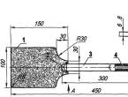
We find a board according to size, approximately and mark it as in the picture.
board markingEverything here is indicated in inches, let's translate. 1 inch equals 2.5 cm, it's simple.
We cut 8 wires 37.5 cm long. We strip the middle of each wire by 2 cm.

We bend each wire with the letter V so that the distance between the wires (its ends) is 7.5 cm.
We cut off 2 wires 42 cm long. We strip these 2 wires at the points of attachment to the board or plywood.
Step 5.
Then I cut two more pieces from the same wire to bring the wires from the center to the back wall of the board. Here you can see the dimensions for yourself, or you can avoid making them at all and attach the wire to the front wall.
We assemble all the wires using self-tapping screws, as shown in the figure at the beginning of the article.
Now let's work with a soldering iron. We only need this plug for the correct resistance so that it is 75 ohms at the output.
To do this, open the lid and do as in the picture below. I screwed the cap itself to the antenna.

Then we attach everything in a convenient place and then the antenna itself. Let's try and use it.
 This is how I did it
 I have had this antenna for over 2 years now. The only thing is that sometimes the antennae themselves bend, as if a strong wind bends or heavy birds perch. But everything can be fixed, I removed it, corrected it and continue to use it.
By the way, I tried without this plug, so as not to suffer, everything works, only a little worse.
Wire antenna with amplifier.
Here is another antenna for digital TV with your own hands, perfect for a country house or village. We make everything from copper wire, and the amplifier can be taken from an old antenna or bought in a store.
What we need:
- Two pieces of wire 180 cm each;
- Amplifier (old one will do);
- A piece of metal or wood plate 15 cm * 15 cm;
- A drill or screwdriver, or a welding machine;
- Small bolts with nuts;
- Hammer;
- TV cable of suitable length.
First, we bend the pieces of wire into a diamond shape with sides of 45 cm. This is the optimal length. But if you make calculations for specific frequencies, then the length will be different, but this is for advanced people.
Now we immediately drill holes on the plate in the places where the diamonds are attached, flatten the ends, which we immediately attach to the amplifier. If the plate is metal, then use a welder to attach the catchers to it and that’s it.
We twist everything together and screw the TV cable wires to the amplifier.
Now we attach the antenna to the mast and point it towards the tower. We use it.
Please note that the entire antenna is painted. This will avoid corrosion and the DIY digital TV antenna will last longer.
Beer cans will help you.
This antenna picks up many different channels well. It is better, of course, to use it indoors and where the repeater tower is not far away.

We will need:
- 2 tin cans of 750 or 1000 ml;
- Coaxial television cable (RK75);
- Antenna plug;
- Electrical tape or tape;
- Self-tapping screws for metal;
- A polypropylene pipe or wooden stick for attaching cans to it;
- Screwdriver;
- Wire cutters;
- Needle file;
- Ruler.
Using a screwdriver, make 1 hole in the neck of each can, making sure that it does not become deformed.
Screw the screws into these holes using a screwdriver.
Step 2.
Clean the ends of the cable with a knife, not forgetting to remove the varnish from the copper wire with a file; screw the wire and cable braid twisted into a ring to the self-tapping screws (it will be more reliable if it is welded or soldered, but this is only if you have the appropriate tool).
Securely secure the cans to a pipe or stick using electrical tape or tape for this purpose, maintaining the distance between the cans (it has long been established experimentally, and this size is 7.5 cm).
Attach a plug to the other end of the cable, which will connect the cable to the receiving device.
Place the antenna in the required location, i.e. where signal reception will be ideal. The most painstaking work is preparing the RK75 cable. One end must be cleaned from the top shell at a distance of 10-12 cm with a knife without damaging the copper braid. Next, you need to twist this braid into a pigtail and remove the aluminum screen. After this, cut off the polyethylene sheath by 6-7 cm and expose the central core. The resulting copper strand and bare core are then attached to the cans. The second end of the cable must also be cleaned and a plug consisting of 2 halves must be connected to it.
The central core of the cable passes through the hole in one half of the plug, and the braid is connected to the plug body. Both halves are screwed on one another, and you get a reliable device for connecting to the antenna socket of the TV.
If you plan to place an antenna made from tin cans outdoors, then it must be reliably protected from external weather influences. Plastic bottles are suitable; you need to cut off the neck and bottom and place the antenna elements in them. In such conditions, it will reliably carry out the functions assigned to it.
This is the simplest broadband antenna, made from scrap materials without the use of special tools, and it is made quickly. You can make it yourself and install it in 20-30 minutes. You can make sure that your homemade antenna receives most satellite television channels, including TVB-T2. At a minimum, it receives up to 15 channels.
Antenna figure eight.
Once upon a time, when there was no digital TV yet, we made such an antenna at school. It is quite simple to manufacture and picks up the signal very well.
It’s a lot to write, and I haven’t made it myself for a long time, here you can watch the video:
Of course, such an antenna is not prohibited, this video just describes the process well.
Buy or find copper wire with a cross-section of 2 - 3 mm. in isolation. Bend the antenna to the dimensions indicated by the author of the video, minimally strip the soldering areas of insulation, solder the cable and seal it from moisture.
If you don’t have a copper wire, you can use aluminum; not much will be lost. The grille can be made from wire, not critical, even from an old refrigerator. If you are in an area of good reception, then it is not necessary to install a grille at all; this is digital and not analogue TV where repetitions on the screen can be observed due to the reflected signal.
What I like about this type of antenna is that it is easy to manufacture, does not require a filter for matching, and has good characteristics. You can increase the power of the antenna if you make it from four squares; you also make a cable tap from the middle, the closest distance between the conductors is 10 mm.
Well, here we have an antenna for digital TV with our own hands and in different ways. That's all for me, leave your comments below, also join us in Odnoklassniki. Bye everyone and see you later.