How to make an electric bike from a regular bike? How to make an electric bike with your own hands from an inexpensive kit Do-it-yourself electric bike from a starter
In our world, full of a variety of machines and automated mechanisms, bicycles stubbornly do not lose popularity. They are remade, modernized, new models of incredible shapes and sizes are created. But at the heart of them are the same two wheels. And today we propose to turn an ordinary bike into an electric bike.
Such models are widely discussed on the net. The controversy around them does not subside, because alterations sometimes cost more than cars. But the author of the video did not strive for glamor or stunning design. Rather, on the contrary, his model of an electric bike can be called a budget one. All parts can be purchased on Chinese sites or in domestic online stores. The bike itself is not overloaded, and thanks to the alteration it looks quite modern. You can make it in a regular home workshop. Is it worth it and is it necessary to bother, once again inventing a "bicycle", let's find out together.
Materials:
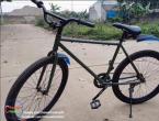
- Regular bike;
- . You can, of course, take a DC motor and control it with;
- Lead accumulator GP1272 F2 – 2 pcs;
- Metal plate (preferably stainless steel or aluminum);
- Aerosol car paint;
- Bolts, screws, nuts, washers;
- Wiring with terminals for connecting contact groups;
- Insulating tape;
- Tight anodized tension spring;
- Powerful loop with small shelves;
- Metal plates for clamps and gaskets;
- A section of a profile pipe 15x15 mm, length - about 50 cm;
- Double tape.
- Drill or screwdriver;
- Bulgarian (UShM);
- welding inverter;
- Drills, cutting and grinding discs for grinders;
- A set of open-end and hex keys;
- Stripper for crimping terminals on wires;
- Screwdriver, pliers, paint knife and tape measure with a pencil.


We assemble an electric bike
The author took a ready-made kit for converting a skateboard into an electric board as the basis for the driving mechanism of his electric bike. It can be bought on Chinese sites complete with an engine and a belt drive within $ 100. A 24-volt motor is provided for them, which works without brushes. For such devices, this is the most advantageous design, the weight is about 500 g, and the power is 1800 W! Of course, with such characteristics of traction, he will have enough to easily pull the bike along with the rider.Step one - we make an electric drive on a suspension
First of all, we put a mounting platform for the engine and a belt drive on the suspension axle. Next, we fix the wheel from the skateboard with the gear on the suspension axle.


Now you need to correctly set the mounting platform for the engine. We unfold it perpendicular to the vertical axis of the suspension, and press the clamping bolt with a hex wrench.


We install the engine on the seat, tighten it with four screws and put on a small gear for a belt drive.


Step two - connect the electrical circuit
The suspension assembly is ready, now it can be connected through the speed controller to the batteries. We connect them in series. The author of the video added a rheostat switch to the circuit in order to be able to smoothly change the voltage and monitor the operation of the engine at the same time.


We disconnect the rheostat (we will no longer need it), and connect the radio-controlled controller-handle with a receiver-transmitter. This equipment is used by skateboarders to control electric boards. A convenient trigger on the handle will allow you to operate such a device easily and naturally.


Step three - fix the driving module on the bike frame
The installation of such a module has its own characteristics. If it is fixed tightly on the bicycle frame, the wheel from the skateboard can wipe the bicycle tire, and the engine can overheat from excessive stress and burn out. In a free position, such a suspension will hang like unnecessary ballast while driving, especially on country roads. Functional fastening requires a fulcrum and a linkage mechanism that will press the skateboard wheel against the tire. We will do it now.We raise the rear fender of the bicycle higher to place the driving module in its place.


The suspension needs to be trimmed slightly by removing the unclaimed second axle from it. We clamp the device in a vise, and with a grinder (angle grinder) we cut it flush with the mounting platform for the board. We clean the cut edges with a grinding disc.


We cut out a protective cover for the driving module from a sheet of metal. We mark it according to the size of the device, and cut it with a grinder. To fix the engine, we make holes for the mounting plate, and sit it on the bolts.


The movable module will be attached to the frame through a small but powerful loop. It will be the axis of our device. On the back of the protective cover, we fix the loop with a welding inverter. We clean the seams with a grinder.


Using a segment of an ordinary door hinge, we make a clamping clamp for fastening to the frame. We paint the protective cover with a loop with an aerosol in the color of the bicycle frame. We fasten it on the bolts to the device of the movable module.


We mount the entire device with a powerful bolt. We drill a hole in the hinge and the frame, we press the bolted connection through it with open-end and box wrenches. You need to adjust its position in such a way that the skateboard wheel is set parallel to the wheel slope, and moves with it in the same plane.


Step four - prepare the lever
The clamping mechanism is made in the form of a small lever. It relies on a rigid spring, determined for compression.We fix a bolt on the cover, which will restrain the movement of the spring, and will not allow it to come off.


We make a lever from a profile pipe 15x15 mm. We mark an angular cut at one end of it, and a 90-degree bend at the other. We make cutouts with a grinder, and weld the connection with a welder.


From an aluminum plate we make a crimp collar to secure the lever to the frame. After cleaning the seams, you can start painting.


Step five - install the electrics on the bike
We place battery banks on the diagonal cross member of the frame. We rest them on a vertical stand and wrap them tightly with adhesive tape, leaving only the contact terminals open. We install the lever on the frame, fix the clamp on the bolted connection, and tighten it with a screwdriver. We put the spring on the seat, and check the pressing force on the tire.


 It all started last year when I started cycling to work more and more often. expectations in the car crowd, after a working day, the moment of arrival home began to strain more and more. The journey by bike from home to work took almost the same time as by car. But taking into account the fact that the path passed most of the way along roads on which there was practically no traffic, along the coastal strip of the reservoir and a picturesque alley, in which sports-oriented people warmed up in the morning, and the shore was decorated with yawning fishermen with fishing rods - riding on riding a bicycle also gave moral satisfaction from admiring everything that was happening around.
The only drawback that overshadowed the trip to work was a hill, about 300 meters long with a rather steep climb, at the entrance to which it was necessary to drop into lower gears and make considerable efforts. The consequence of this was not a comfortable state before the start of the working day in the office.
The idea was born to equip your bike with an engine that would help in difficult times. After studying quite a few YouTube videos, the endless-sphere.com forum, and other resources about electrifying a bicycle at home, a picture of the solution to the problem formed in my head. It remains only to implement.
The idea of buying a ready-made kit with a front-wheel drive motor seemed trivial to me, and two other reasons: low power output (up to 500 W) and high cost - did not play in her favor.
Emphasis was placed on rear-wheel drive and the use of a brushless motor. The efficiency of such a solution, it seemed, should be higher than the use of a front-wheel drive motor-wheel.
Already having little experience in radio modeling, I decided to use components from HobbyKing to implement my idea, as the main ones when building an electric bike. Mechanics, it was decided to use one that is easy to get in any auto or bike shop.
Components
The following components were used to build the electric bike:
HobbyKing
Engine (1500 rubles)
Engine controller (700 rubles)
Rechargeable battery (1300 rubles)
Servo tester (200 rubles)
Charger (700 rubles)
Power wires (red / black) (200 rubles)
Connectors 1, connectors 2 (200 rubles)
Wattmeter (optional) (600 rubles)
Heat shrink (optional)
car shop
Alternator pulley VAZ-2108, 4 pcs. (500 rubles)
Alternator belt VAZ-2108, 2 pcs. (200 rubles)
bike shop
Freewheel (150 rubles)
Sleeve, 2 pcs. (500 rubles)
Chain (150 rubles)
Gear switch (300 rubles)
Star 52T (300 rubles)
Hardware store
Diamond disc 150 mm (150 rubles)
Screws, nuts, washers (150 rubles)
Aluminum profile 20×10 (100 rubles)
Total 7300 rubles.
Since I planned to build an electric bike with rear-wheel drive, I decided to use a chain drive to transmit torque to the rear wheel, and to increase the transmission ratio, put a star with a large number of teeth.
Initially, I planned to cut a star with the right number of teeth using laser cutting in some workshop, but the search for a finished 3D template of the desired configuration took a lot of time and did not lead to anything worthwhile. The order for cutting, along with the manufacture of the template by the designer, cost a pretty penny (about 1,500 rubles). This nullified the main principle of the conceived idea - minimizing the cost of custom-made and using affordable off-the-shelf low-cost components.

Therefore, the largest chainring 52T, removed from the cassette, was purchased at the bike shop (bike workshop). And to attach it to the rear wheel hub, a diamond disc for a grinder of a suitable diameter (15 cm) was bought in a hardware store. The central hole of the disk had to be bored with a drill and a file to the desired diameter of the rear wheel hub. The fastening of this design to the rear wheel is made with three bolts to the spokes. It is advisable to use “eared” nuts for fastening, which cling well to the spokes, as well as auto-lock nuts (with an insert). The star should be balanced on a spinning wheel so that there are no beats in different directions.


To prevent torque from being transferred to the motor from a spinning wheel, I used a 16 tooth free wheel, which is easy to buy at any bike shop. The problem is that it is designed to be used with stronger chains and standard narrow chains will not sit on it. To make this possible, it is necessary to grind the teeth of the freewheel a little on the sides. I used a hand drill with a whetstone attachment for this. 10 minutes and you're done - with a file it would take a long time.

Since the freewheel is designed to be screwed onto the rear thick sleeve, it has a large diameter internal thread and an adapter is required to attach it to the transfer sleeve (with a thread diameter of 10 mm). I could also find such an adapter in a bike shop. It was sold complete with a black sleeve and I do not know what it is for. The photo shows the second same adapter, which was on the other side with a reverse thread.

To tension the chain from the freewheel to the rear wheel sprocket, I used a standard inexpensive derailleur. The tensioner configuration turned out, of course, not the most successful, but in general it fulfills its role, and I could not think of anything better.


For the gradual transfer of torque from the engine to the freewheel, I used two adapter bushings with pulleys installed on them under the VAZ-2108 generator V-belt. The whole structure is fixed with aluminum profiles on the bicycle frame.
UPD. The frame should not be made of composite materials such as carbon, because. it must be solid and undamaged to maintain strength. Otherwise, the frame may burst. The use of aluminum frames is also not recommended. It is best to use as I have a steel frame.

Transition bushings are also not ordinary. They have a much larger diameter of the planes where the spokes are attached. This made it possible to attach them to aluminum profiles. To do this, we drill holes for the knitting needles a little under the M3 screws.

Pulleys for belts have a larger inner diameter than the thread diameter of the adapter sleeve, therefore, to avoid inaccurate installation of the pulleys, I wound electrical tape layer by layer on the thread of the sleeve up to the diameter of the pulley hole, and used washers with a diameter of 30 mm to fix under the nuts.

In principle, one V-belt transmission link can be used. The power reserve of the engine is enough for driving on straight roads and small slopes. But for confident driving on sand and hills, it is better to use two links. Each link has a multiplicity of about 2x. Thus, increasing the torque transmitted to the wheel by 2 times.
I attached the motor controller with zip ties to one of the aluminum profiles attached to the frame, using thermal paste for better contact. This allows you to better remove heat from the controller and during the ride it feels like the profile and frame in the vicinity of the controller heat up. On the other side of the controller, where its heatsink is installed, I carefully cut off the heat shrink with a knife and attached a small fan from the old Intel 586 processor. Although, according to operating experience, it turned out to be unnecessary.


To control the power of the motor, I used a servo tester set to manual control mode. The L7805 (KREN5A) chip is used to power the servo tester and the cooling fan.

First, I unsoldered a variable resistor from the servo tester and placed it next to the right grip on the handlebar. It turned out that this method of smooth power adjustment has its drawbacks. It is especially inconvenient to use it in extreme situations when you have to brake sharply, when the hand moves to the brake lever, and the engine continues to deliver torque to the braking or even blocked wheel.
Therefore, I simplified the circuit and made a miniature reed button “gas to the floor” (without fixation) under the thumb of the right hand, when pressed, the engine starts to produce maximum power. To eliminate sharp jerks, I put a voltage divider on two resistors and a 100 microfarad capacitor at the input of the servo tester. Thus, it ensured a smooth increase and decrease in engine speed when pressing and releasing the “gas to the floor” button in about 0.5 - 0.7 seconds.

I put a wattmeter on the steering wheel to control the battery voltage and measure the “flow” of the capacity stored in the battery. The battery is housed in a zippered saddle bag. Thus, he killed two birds with one stone - the battery is easily removed for recharging and during operation it is in a closed safety case, in case of an emergency failure.


I put a reed button (non-latching) on the left handle on the steering wheel for a sound signal to scare away pedestrians. As a signal, I used a piezocrystalline car siren - a whistle. It feels quite normal during short-term operation at a voltage of 22 V (battery 6s). Only louder than 12 V.
Results
I will describe several advantages and disadvantages of the applied solutions. In order.
The chain drive to the rear wheel has a rather long run, which causes the chain to fly off the free wheel when driving on a bumpy road. To avoid this, it was necessary to fence some kind of chain guide in front of the freewheel from a piece of aluminum strip and a plastic roller. Since the chain beats against it when moving, this creates an unpleasant loud knocking sound. For good, it is necessary to put a chain tensioner or damper in front of the freewheel, but I have not yet figured out how.
Mounting the rear driven star to the wheel is not the most reliable. There is a possibility of damage to the spokes or jumping off the fastening of the star from the spokes. This has already happened once when I used ordinary nuts. After that, I installed the “ear nuts” and auto-locknuts. It is better to change the current hub to a hub with a disc brake mount and put a large star in its place. But since the sprocket diameter is much larger than the disc brake, I'm not sure if the distance to the frame is enough for free rotation.
The wedge transmission of power from the engine to the freewheel worked reasonably well at first. However, the efficiency of such a solution leaves much to be desired. With an increase in belt tension, the load on the bearings of the adapter bushes and the motor increases, which leads to an increase in wear and friction forces, and hence a decrease in transmission efficiency. With a decrease in tension, the belts at high loads (starting from a place, moving uphill) begin to slip, and this also leads to a decrease in efficiency. Finding a balance is extremely difficult. The use of V-ribbed pulleys is problematic due to their bulkiness. The best solution seems to be the use of a toothed belt drive.
Controlling the power of the engine, as in the first version, using a variable resistor, as I already wrote, is often inconvenient. Using the “gas to the floor” button is often unjustified, because. There are times when you need to drive slowly and smoothly. The movement pattern “gas to the floor - acceleration - run-out in neutral”, although in terms of battery capacity consumption is almost comparable in efficiency to movement with constant engine operation, it has an important drawback - slippage of the V-belt during acceleration. But in the “gas to the floor” mode, you feel all the power installed under your seat.
Well, it doesn’t matter, but still, the sound of a running engine and a moving chain with an open structure often frighten passers-by. If any of the modellers knows how brushless engines whistle, he will understand.
Some interesting facts
Based on the diameters of the V-pulleys (150 mm and 80 mm) and the number of teeth of the freewheel and star on the rear wheel (16 and 52), we find that the total gear ratio is 11.4. This is not very much and is not enough for a quick ride uphill, you have to help with your feet. Therefore, I put a ceramic pulley from a washing machine (bought at a flea market) with a diameter of 64 mm on the engine. This made it possible to increase the gear ratio to 14.3. With a battery voltage of 22.2 V, the maximum theoretical speed will be 45 km/h. Taking into account air resistance and power losses in the transmission links, it seems to be true, because in a straight line, I accelerated to 40 km / h.
The battery with a capacity of 5000 mAh (22 V) lasts for 30 minutes of driving and 8-10 km of travel at an average speed of 18 km/h and accelerations up to 40 km/h. Even earlier, when I had a 2200 mAh (11 V) battery, it was also enough for me for 8 km, but at a maximum speed of 18 km / h, an average of 14 km / h and pedaling assistance to the engine when driving uphill.
The maximum current consumed by the engine during acceleration in the “gas to the floor” mode is about 60 A. Thus, the output power is about 1250 W, which is several times higher than most of the motor wheels sold. Acceleration to 40 km / h in a straight line no more than 10 seconds.
In the current configuration, I drove last season from July to October almost every day to work with a daily mileage of about 20 km.
The idea to install an electric drive on a bicycle suggests itself. Indeed, why is an internal combustion engine possible (this has been practiced for a very long time), but an electric one is not? With the current level of electronics, such a bike upgrade should be even easier than using other engines. In addition, this will not require coordination with the registration services of the traffic police.
For those for whom this transport is the main means of transportation (for example, for daily trips to and from work), the electrification of the “two-wheeled friend” will allow significantly save your strength and nerves. There is no need to stand idle in traffic jams that are not uncommon at the present time, the speed of an electric bicycle for urban conditions is decent, so the actual travel time is often even reduced compared to conventional ground personal or public transport.
Tired of just riding? Master it! The article tells how to learn to ride on the back wheel.
For those who want to learn skateboarding, our how to choose, buy and learn to ride a skateboard.
By constantly recharging the batteries, at home or in any available place, you can have a significant margin of mileage, and, with the correct calculation of the route and battery capacity, you can always be confident in your capabilities. Yes, in the end, in case of unforeseen troubles, you can get there in the usual way - on the pedals.
Currently, it is possible, without much difficulty, to purchase a ready-made electric bike, but its cost is quite high. Is it possible to re-equip your faithful "horse" yourself? It turns out that this is quite real, and many masters share their secrets online.
Some of them carry out a deep "upgrade" of bicycles, using completely unexpected design ideas, components and materials, often purchased at a "flea market" or in auto shops. Less "advanced" simply purchase ready-made kits for the electrification of cycling - fortunately, manufacturers offer them in a fairly wide range.
What are the types of transmission of rotational motion from the engine to the drive wheel?
friction gear
 This type of electric drive, although it is found on sale, is not particularly popular. Its principle is simple. The engine is installed directly at the drive wheel, the torque is transmitted directly from the stator shaft to the tire. It would seem that everything is simple and obvious. But what may be applicable for children's electric cars and bicycles is of little use in the actual use of transport.
Judge for yourself:
- There are no transmission links, that is, the possibility of increasing the angular velocity of the wheel through the use of gearboxes is excluded;
- Extremely low efficiency;
- Even a slight drop in pressure in the wheel chamber will drastically reduce the efficiency of such a drive.
- Constant friction between the engine clutch and the tire tread dramatically reduces its durability.
- In wet weather, dirty roads, frost, the coefficient of friction will significantly decrease, the friction clutch will slip, which will reduce the already low energy efficiency of the drive.
The only advantage of this system is the ease of installation, which does not require any deep modifications to the bike.
No, if you plan a rework with real improvements in the performance of the bike, it is better to immediately abandon such a scheme.
Classic chain or belt drive
This principle is most often used by craftsmen - "homemade", because of its visual "comprehensibility" and a wide selection of necessary components from conventional bicycles. As an engine, electric motors from household appliances (for example, from a washing machine) or automotive electrical facilities are often used.
What can be said about shortcomings similar drive?
- It should be noted right away that altering a bicycle in this way will require the owner to have a fairly deep knowledge of mechanics and high technological skills.
- Another disadvantage is the noisiness of the system with this type of transmission, but in road conditions this is unlikely to cause significant inconvenience to anyone.
- The refinement is associated with some changes in the frame design, which can reduce its strength characteristics. In any case, it is not recommended to carry out such work on bicycles with carbon or aluminum frames - only on steel ones.
But the shortcomings are brightened up by a number benefits:

It is clear that here is the widest field for creative design ideas. However, manufacturers did not forget about cyclists - there are ready-made kits for electric bikes on sale. The kits from the Taiwanese company Cyclone are the most popular.
Similar "constructors" are produced in different versions - using a standard bicycle chain, or with the transfer of force through an additional chain with one or two additional sprockets.
Systems equipped with electric motors power from 360 to 1500 W, with a supply voltage of 24 or 36 volts. To control the operation of the drive are used electronic controllers, and in engines up to 500 watts, they are usually built-in. The kit includes all necessary fasteners, means of visual control and manual control of the drive.
Installing an electric drive will be quite a feasible task for any owner with “properly growing hands”.
The overall weight of the bike is quite acceptable - 3-4 kilograms, but the speeds that it can develop are very impressive - 40 or more kilometers per hour.
The simplest solution is a motor-wheel
 For lovers of lightweight cycling, manufacturers offer another option in which the electric motor and wheel are structurally arranged into one unit, the so-called motor-wheel.
Advantages such a system are obvious:
- When installing this drive, the bike does not undergo any significant modifications, and its appearance does not change significantly. The only thing is the installation of controls on the steering wheel and the battery compartment on the frame.
- Installation does not require any significant knowledge and skills - with the right selection of the motor wheel, it is probably available to everyone.
- The engine is almost silent.
- If desired, the bike can be easily transformed back into a regular one.
There are, of course, a number shortcomings:
- A wheel with a drive placed in it is a rather heavy structure (6 or more kilograms), which increases the total mass of the vehicle. Experienced cyclists recommend installing a reinforced front fork.
- There are certain limits on drive power.
- Exceeding the speed set by the manufacturer can have the opposite effect - the engine turns into a generator and spontaneously slows down the movement.
The kits sold are a brushless electric motor assembled in the wheel hub with a power of 200 to 1000 watts.
As a rule, ready-made designs go on sale - with spokes and a wheel rim, however, for those who like to approach the matter, simply engines are also implemented in detail. In this case, the choice and installation of the necessary spokes and rims falls on the owners of the transport. So to speak, a do-it-yourself motor-wheel.
The kit necessarily includes a controller that ensures the correct operation of the drive, control mechanisms, batteries with a recharging unit.
 Depending on preferences, you can choose both front and rear drive wheels. Some cyclists solve the problem "in one fell swoop" - they make their "car" all-wheel drive.
Wheel motors are considered the most popular among fans of the electric drive. "Polaris", "Yamasaki", "Electra", "Golden motor". You can buy them both through specialized stores and by ordering via the Internet.
Having realistically assessed your need for an electric bike, financial solvency and technical readiness to perform your own installation, you can make a choice in favor of one or another model.
Video
It uses an electric motor that consumes 48 volts.
The idea of constructing an electric bike from an ordinary pedal bike is visited by many, but only a few people realize it in reality: some do not have enough time, others lack experience. Very often, such an idea comes to mind when it is especially difficult to pedal, climbing, for example, uphill or moving towards the wind. There are many options for DIY enthusiasts: these and use as a “driving force”, i.e. a motor, an engine from a chainsaw, and from a washing machine, and a motor-wheel, etc.
For those who are used to achieving goals, the result is an amazing and exclusive vehicle that is a pleasure to drive.
One of the options where you will need to change the frame is presented to everyone who is facing the problem of how to make an electric bike with their own hands.

First of all, starting work on creating a new design of a bicycle with an electric motor, you will need to purchase: a Felt beach cruiser, chosen for its powerful frame, to which the main elements and correct forms will be attached. You can choose another model.
The main thing is that there is a reliable frame that will allow you to fix the elements, so that the center of gravity will be as low as possible.
To make this vehicle with a motor, you need to buy:
- An electric motor (in this case, Briggs and Stratton).
- The controller is similar to Alltrax AX 300A.
- Throttle knob (in our case, Magura 0-5K Ohm).
- Lead battery, which includes four batteries 12V, 21A / h.
- Brake type Avid Bb7 160mm disc.
- Chain #35.
- Two sprockets: driving and driven (respectively with the number of teeth 13 and 66).
- 300 amp fuse.
- To replace the carriage, you will need a stainless steel motor support.
Operating procedure

We immediately replace the “native” fork with a suspension fork. We install disc brakes, which need to be fixed using bolts.

Since the bicycle model you purchased has a foot brake, i.e. braking occurs when the pedals move in the opposite direction;

As a rear bushing, a bushing is used, made in the form of a front double bushing with a standard fastening (six bolts). There are no mounting holes in the 66 tooth sprocket, so they need to be drilled in such a way that they match the mount. It is very important that the hub, both sprockets and the brake rotor are on the same axle.

A steel sheet is used as the material from which the brake mount is cut out, as well as the engine. Then the mount is attached to a stainless steel ring, welding it strictly in the center in the place where the carriage was previously located. By welding the old lighting stands together, you can get an excellent fastening of the footrests.


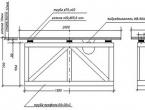
The ring is a structure, the width of which is 1 cm, and the diameter is 21 cm. Given the size of the motor chosen for installation, the gap will be about three centimeters. For blowing air into the engine, holes are drilled in the ring. You also need to make a notch in it on the right in order to provide free play for the chain. A mount for an electric motor is welded inside, as well as so that the steps can be made removable.

It is also recommended to shorten the saddle holder and weld it to the frame in the area where the rear wheel is located, reinforcing the design with an additional insert. We put a rubber cap on the seat tube, then unfold the saddle clamp.

The overall look of the new bike is reminiscent of a retro motorcycle due to the low saddle and powerful wheels. The photo shows a hole in the top tube of the frame. It is necessary for the cable that controls the rear brake.

Hatches for aluminum batteries are located from the battery trays to the right and left. They are fixed with bolts. The controller is mounted upside down under the top tube.

After completing the assembly, you can proceed to the electrical part - connecting wires, testing for several hours.
Specifications
Quickly, as testing has shown, the assembled structure accelerates, developing as much as possible speed about 80 km/h. With help RS-232 port sequentially, the controller is connected to the bike computer.
It is much more pleasant to ride a bicycle, and even assembled with your own hands, so you should not waste time, but you need to get to work.