Circuits of simple low frequency generators. The simplest audio frequency generator Description of the circuit diagram of a sound generator
What is a sound generator and what is it used for? So, let's first define the meaning of the word “generator”. Generator – from lat. generator- manufacturer. That is, to explain in everyday language, a generator is a device that produces something. Well, what is sound? Sound- these are vibrations that our ear can discern. Someone farted, someone hiccupped, someone sent someone - all these are sound waves that our ears hear. A normal person can hear vibrations in the frequency range from 16 Hz to 20 Kilohertz. Sound up to 16 Hertz is called infrasound, and the sound is more than 20,000 Hertz - ultrasound.
From all of the above, we can conclude that a sound generator is a device that emits some kind of sound. Everything is elementary and simple;-) Why don’t we assemble it? Scheme to the studio!
As we can see, my circuit consists of:
– capacitor with a capacity of 47 nanoFarads
– resistor 20 Kilohm
– transistors KT315G and KT361G, maybe with other letters or even some other low-power ones
– small dynamic head
- a button, but you can do it without it.
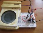
On the breadboard it all looks something like this:
.JPG)
And here are the transistors:

On the left is KT361G, on the right is KT315G. For KT361 the letter is located in the middle of the case, and for 315 it is on the left.
These transistors are complementary pairs to each other.
And here is the video:
The frequency of the sound can be changed by changing the value of the resistor or capacitor. Also, the frequency increases if the supply voltage is increased. At 1.5 Volts the frequency will be lower than at 5 Volts. In my video the voltage is set to 5 Volts.
Do you know what else is funny? Girls have a much greater range of perception of sound waves than boys. For example, guys can hear up to 20 Kilohertz, and girls can even hear up to 22 Kilohertz. This sound is so squeaky that it really gets on your nerves. What do I want to say by this?)) Yes, yes, why don’t we choose resistor or capacitor values such that girls hear this sound, but boys don’t? Just imagine, you are sitting in class, turning on your organ and looking at the dissatisfied faces of your classmates. In order to set up the device, we will of course need a girl to help us hear this sound. Not all girls also perceive this high-frequency sound. But the really funny thing is that it’s impossible to find out where the sound is coming from))). Only if anything, I didn’t tell you that).
Sound generator type "ZG-10"
Purpose and scope
The sound generator type "ZG-10" is a portable laboratory device designed to produce sinusoidal low-frequency alternating current voltages.
It was manufactured according to the technical specifications of TU No. 0.506.020-54 and is designed for operation at ambient temperatures from +10 to +30 degrees. C and relative humidity up to 80%.
The device type "ZG-10" is used for adjusting and testing low-frequency stages of radio equipment in laboratory and workshop practice.
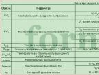
Main technical characteristics
- The range of generated frequencies from 20 to 20000 Hz is divided into three subranges:
a) 20 - 200 Hz with a multiplier x1;
b) 200 - 2000 Hz with a multiplier x10;
c) 2000 - 20000 Hz with a multiplier of x100. - The frequency calibration error does not exceed +-2% +- 1 Hz.
- Frequency instability when the supply voltage changes by +-10% of the nominal value does not exceed +-0.2%.
- The frequency change after 30 minutes of preheating does not exceed 3 Hz at a frequency of 1000 Hz for the first hour of operation and 4 Hz for the next seven hours of operation.
- The maximum output voltage is 150 V with a maximum power of 5 W.
- The output of the device is designed for symmetrical and asymmetrical loads with a resistance of 50, 200, 600 or 5000 Ohms.
- The unevenness of the frequency response relative to the normal level at a frequency of 400 Hz does not exceed +-1.5 dB.
- When the supply voltage changes by +10%, the output power changes by no more than +5%.
- The coefficient of nonlinear distortion does not exceed 0.7%.
- Output voltage indicator with a measurement limit of 60 V. The calibration error of the indicator scale at a frequency of 1000 Hz and with a load of 600 Ohms does not exceed +-5%.
- Output voltage is adjustable:
a) smoothly - ranging from zero to maximum value;
b) in steps - in steps of 1 dB to 110 dB using two dividers - the first, in steps of 10 to 100 dB and the second, in steps of 1 dB to 10 dB.- The device uses the following lamps: 6Zh8 - 1 pc.; 6P9 - 1 piece; 6N8S - 1 pc.; 6С4С - 2 pcs.; 5TS3S - 1 pc.; 6Х6С - 1 pc. and TP-6/2 1 pc.
- The device is powered from an alternating current network with a frequency of 50 Hz and a voltage of 110, 127 or 220 V + -10%.
- Power consumption 150 W.
- Overall dimensions of the device are 598 x 357 x 293 mm.
- The weight of the device is about 35 kg.
The circuit of a sound generator of the "ZG-10" type consists of the following main elements: a generator, an amplifier, an output voltage indicator, an output device and a rectifier.
The generator is a two-stage amplifier assembled on 6Zh8 and 6P9 tubes and excited by positive feedback, which is carried out by a phasing chain consisting of resistances and capacitors and providing excitation of the generator at a frequency specified by the parameters of this chain. The generator frequency is changed by changing the parameters of the phasing chain.
The generator circuit is covered by negative feedback, ensuring frequency stability and minimal nonlinear distortion.
The negative feedback circuit uses a thermistor, which acts as a nonlinear resistance to ensure that the amplitude of the generated signal remains constant.
The amplifier is assembled according to a two-stage circuit using 6N8S, 6S4S and 6S4S tubes. The first stage, assembled on a 6N8S lamp, is a bass reflex. The second stage, assembled on two 6C4C tubes, is a push-pull power amplifier.
The output voltage indicator is a lamp voltmeter, arranged according to the circuit of a full-wave rectifier assembled on a 6X6C lamp. An M5 type magnetoelectric device of class 2.5 is used as an indicator.
The output device consists of two dividers assembled according to a bridge and matching transformer circuit. The first divider gives an attenuation of up to 100 dB in steps of 10 dB and the second up to 10 dB in steps of 1 dB.
The matching transformer is used to match the generator output with a load of both symmetrical and asymmetrical resistance of 50, 200, 600 or 5000 Ohms.
The rectifier is assembled using a full-wave circuit using a 5Ts3S type lamp with a two-section L-shaped filter. The rectifier is powered from an alternating current network with a frequency of 50 Hz and a voltage of 110, 127 or 220 V.
Design
The device is assembled and mounted on a metal vertical panel and a horizontal chassis, placed in a metal casing equipped with handles for carrying. On the front panel of the device there are:
- frequency setting knob with dial;
- output voltage indicator;
- indicator light;
- power switch;
- "multiplier" switch;
- output voltage setting knob;
- load switch;
- output terminals;
- switch for “high-resistance load”;
- two output device attenuator switches.
Such a device will be very useful when testing audio circuits of amplifiers of receivers, televisions and other industrial and home-made equipment. The generator circuit is based on the book by V. G. Borisov “Young Radio Amateur” (from 145-146 in the 8th edition), with minor changes.
AF generator circuit
The generator is assembled on a K155LA3 microcircuit (you can use K555LA3), which consists of 4 2I-NOT elements. The generator itself is formed by series-connected logic elements DD1.1, DD1.2, DD1.3, connected by inverters. Capacitor C1, with a capacity of 0.47 μF, creates positive feedback between the output of DD1.2 and the input of DD1.1. In principle, the signal can be taken from the output of DD1.3; the DD1.4 element simply inverts them. The pulse frequency can be changed using a variable resistor R1. Resistor R2 serves as a regulator of the output signal level. Resistor resistance R1 680 Ohm, R2 10 kOhm, variable resistors can be of any type. With the parameters of radio components indicated in the diagram, the pulse frequency can be changed within 500 - 5000 Hz. Diode VD1 serves to protect against power supply of incorrect polarity; any low-power diode, for example D220, is suitable for it. The circuit is mounted on a small breadboard. But thanks to the small number of parts, the circuit can be mounted using a wall-mounted design.
Generator assembly

The standard supply voltage of the K155 and K555 microcircuits is 5 V, but the generator is operational when powering the circuit from a “square” battery with a voltage of 4.5 V (battery type 3336 according to the old nomenclature), the voltage drop across the VD1 diode does not affect the operation of the device. The device can be used for audio frequency.
AppliancesTransistor sound generator circuit
A sound wave generator is a device or electrical circuit unit responsible for creating and reproducing sound vibrations.
Where such a device can be useful:
1. A simple electric doorbell (when the contacts of a remote button are closed, a sound alert about visitors occurs);
2.Alarms (when the security system is triggered, the sound warning unit is activated);
3. Formation of a certain timbre of sound in sound equipment;
4. Repelling insects/birds (by emitting sound vibrations at certain frequencies);
5. In other professional equipment (testing low-frequency circuits, testing parts for defects and other purposes based on the properties of sound waves).
The simplest transistor sound generator
Below is a diagram with a minimum number of radio components. It can be useful for beginning radio amateurs, in radio circles, in test benches, for doorbells, etc.
In everyday life it is also called a “squeaker”.

VT1 is an n-p-n type bipolar transistor, for example, KT315. Any one will do, even low-power ones.
VT2 is bipolar, but p-n-p n type, for example, KT361. Any will do too.
Oscillations are set by a capacitor; its capacitance should be in the range of 10-100 nF.
The resistor is a trimmer, suitable with a value in the range of 100-200 kOhm.
Speaker BA1 should be low-power, its parameters should be comparable to the parameters of the power element. In this scheme, any available material can be used - from toys or headphones.
If the elements are arranged correctly, a printed circuit board will not be needed.
Improvement to the "game panel"
Using this scheme, you can assemble an entire panel capable of generating sound vibrations of various frequencies:
1. Since the capacitance of the capacitor is responsible for frequency generation, the number of conclusions can be made according to the number of different capacitors available (preferably in large increments so that the change in frequency is immediately noticeable to the ear.
2. One terminal of the capacitors will be common to everyone, and is connected, for example, to the base of VT1 or the speaker contact.
3. The second terminals are connected to the terminals of single galvanic contacts on the panel.
4. Now, to get sound, it is enough to include a new capacitor in the circuit only by connecting any of the output contacts to the second common point in the circuit (if the first common terminal was connected to the base of VT1, then the second to the emitter of VT2/speaker contact, or vice versa).
5.If desired, the switch can be excluded from the circuit.
As an example.

Another simple implementation is in the diagram below.

More complex scheme
If you need the ability to adjust audio frequencies within a given range, then the diagram below may be useful to you.
Low frequencies are designed to produce periodic low frequency electrical signals with specified parameters (shape, amplitude, signal frequency) at the output of the device.
KR1446UD1 (Fig. 35.1) is a general-purpose dual nut-rail op-amp. Based on this microcircuit, devices for various purposes can be created, in particular, electrical oscillations, which are shown in Fig. 35.2-35.4. (Fig. 35.2):
♦ simultaneously and synchronously generates voltage pulses of rectangular and sawtooth shape;
♦ has a common artificial midpoint for both op-amps, formed by the voltage divider R1 and R2.
On the first of the op-amps, a Schmitt amplifier is built, on the second, with a wide hysteresis loop (U raCT = U nHT ;R3/R5), accurate and stable switching thresholds. The generation frequency is determined by the formula:
f =———– and is 265 Gi for the denominations indicated in the diagram. WITH
Rice. 35.7. Pinout and composition of the KR 7446UD7 microcircuit

Rice. 35.2. generator of rectangular-triangular pulses on the KR1446UD 7 microcircuit
By changing the supply voltage from 2.5 to 7 V, this frequency changes by no more than 1%.
The improved one (Fig. 35.3) produces rectangular pulses, and their frequency depends on the control value

Rice. 35.3. controlled square pulse generator
input voltage according to the law
![]() When it changes
When it changes
input voltage from 0.1 to 3 V, the generation frequency increases linearly from 0.2 to 6 kHz.
The generation frequency of the rectangular pulse generator on the KR1446UD5 microcircuit (Fig. 35.4) linearly depends on the value of the applied control voltage and when R6=R7 is determined as:

5 V generation frequency increases linearly from 0 to 3700 Hz.

Rice. 35.4. voltage controlled generator
So, when the input voltage changes from 0.1 to
Based on TDA7233D microcircuits, using the basic element as a single basis, Fig. 35.5, a, it is possible to collect sufficiently powerful pulses (), as well as voltages, Fig. 35.5.
The generator (Fig. 35.5, 6, top) operates at a frequency of 1 kHz, which is determined by the selection of elements Rl, R2, Cl, C2. The capacitance of the transition capacitor C sets the timbre and volume of the signal.
The generator (Fig. 35.5, b, bottom) produces a two-tone signal, subject to individual selection of the capacitance of capacitor C1 in each of the basic elements used, for example, 1000 and 1500 pF.
The voltages (Fig. 35.5, c) operate at a frequency of about 13 kHz (the capacitance of capacitor C1 is reduced to 100 pF):
♦ upper - generates voltage that is consistent with respect to the common bus;
♦ medium - generates twice the positive voltage relative to the supply voltage;
♦ lower - depending on the transformation ratio, it generates a multipolar equal voltage with galvanic (if necessary) isolation from the power source.

Rice. 35.5. abnormal use of TDA7233D microcircuits: a – basic element; b - as pulse generators; c - as voltage converters
When assembling converters, it should be taken into account that a noticeable part of the output voltage is lost on the rectifier diodes. In this regard, it is recommended to use Schottky as VD1, VD2. The load current of transformerless converters can reach 100-150 mA.
Rectangular pulses (Fig. 35.6) operate in the frequency range 60-600 Hz\ 0.06-6 kHz; 0.6-60 kHz. To correct the shape of the generated signals, a chain can be used (lower part of Fig. 35.6) connected to points A and B of the device.
Having covered the op-amp with positive feedback, it is not difficult to switch the device to the mode of generating rectangular pulses (Fig. 35.7).
Pulses with smooth frequency adjustment (Fig. 35.8) can be made based on the DA1 microcircuit. When using LM339 microcircuit 1/4 as DA1, by adjusting potentiometer R3, the operating frequency is adjusted within the range of 740-2700 Hz (the nominal value of capacitance C1 is not indicated in the original source). The initial generation frequency is determined by the product C1R6.

Rice. 35.8. wide-range tunable oscillator based on a comparator

Rice. 35.7. rectangular pulse generator at a frequency of 200 Hz

Rice. 35.6. LF rectangular pulse generator
Based on comparators such as LM139, LM193 and the like, the following can be assembled:
♦ rectangular pulses with quartz stabilization (Fig. 35.9);
♦ pulses with electronic tuning.
Frequency-stable oscillations or so-called “clockwise” rectangular pulses can be made on a DAI LTC1441 comparator (or similar) according to the standard circuit shown in Fig. 35.10. The generation frequency is set by the quartz resonator Z1 and is 32768 Hz. When using a line of frequency dividers by 2, rectangular pulses with a frequency of 1 Hz are obtained at the output of the dividers. Within small limits, the operating frequency of the generator can be reduced by connecting it in parallel with a small-capacity resonator.
Typically, LC and RC- are used in radio electronic devices. LR- are less known, although devices with inductive sensors can be created on their basis,

Rice. 35.11. LR generator

Rice. 35.9. pulse generator on comparator LM 7 93

Rice. 35.10. "clock" pulse generator
Detectors for electrical wiring, pulses, etc.
In Fig. Figure 35.11 shows a simple LR rectangular pulse generator operating in the frequency range 100 Hz - 10 kHz. As inductance and for sound
To control the operation of the generator, a TK-67 telephone capsule is used. Frequency adjustment is carried out by potentiometer R3.
Operable when the supply voltage changes from 3 to 12.6 V. When the supply voltage decreases from 6 to 3-2.5 V, the upper generation frequency increases from 10-11 kHz to 30-60 kHz.
Note.
The range of generated frequencies can be expanded to 7-1.3 MHz (for a microcircuit) by replacing the telephone capsule and resistor R5 with an inductor. In this case, when the diode limiter is turned off, signals close to a sinusoid can be obtained at the output of the device. The stability of the device's generation frequency is comparable to the stability of RC generators.
Sound signals (Fig. 35.12) can be performed K538UNZ. To do this, it is enough to connect the input and output of the microcircuit with a capacitor or its analogue - a piezoceramic capsule. In the latter case, the capsule also serves as a sound emitter.
The generation frequency can be changed by selecting the capacitance of the capacitor. You can turn on the piezoceramic capsule in parallel or in series to select the optimal generation frequency. Generator supply voltage 6-9 V.

Rice. 35.72. audio frequencies on the chip
For express testing of the op-amp, the audio signal generator shown in Fig. 35.13. The tested DA1 microcircuit, type , or others with a similar pinout, is inserted into the socket, and then the power is turned on. If it is working properly, the piezoceramic capsule HA1 emits a sound signal.

Rice. 35.13. sound generator - op amp tester

Rice. 35.14. rectangular pulse generator based on OUKR1438UN2

Rice. 35.15. sinusoidal signal generator on OUKR1438UN2
A square wave signal at a frequency of 1 kHz, made on the KR1438UN2 microcircuit, is shown in Fig. 35.14. amplitude-stabilized sinusoidal signals at a frequency of 1 kHz are shown in Fig. 35.15.
A generator producing sinusoidal signals is shown in Fig. 35.16. This one operates in the frequency range of 1600-5800 Hz, although at frequencies above 3 kHz the waveform becomes increasingly less ideal and the output signal amplitude drops by 40%. With a tenfold increase in the capacitances of capacitors C1 and C2, the tuning band of the generator, while maintaining the sinusoidal shape of the signal, is reduced to 170-640 Hz with an uneven amplitude of up to 10%.

Rice. 35.7 7. sinusoidal oscillation generator at a frequency of 400 Hz