A simple radiation indicator for SBM 20 diagram. Geiger counter made easy. Counter dead time
Attention!!! Delivery of ALL devices that are listed on the website takes place throughout the ENTIRE territory of the following countries: Russian Federation, Ukraine, Republic of Belarus, Republic of Kazakhstan and other CIS countries.
In Russia there is an established delivery system to the following cities: Moscow, St. Petersburg, Surgut, Nizhnevartovsk, Omsk, Perm, Ufa, Norilsk, Chelyabinsk, Novokuznetsk, Cherepovets, Almetyevsk, Volgograd, Lipetsk Magnitogorsk, Tolyatti, Kogalym, Kstovo, Novy Urengoy, Nizhnekamsk, Nefteyugansk, Nizhny Tagil, Khanty-Mansiysk, Yekaterinburg, Samara, Kaliningrad, Nadym, Noyabrsk, Vyksa, Nizhny Novgorod, Kaluga, Novosibirsk, Rostov-on-Don, Verkhnyaya Pyshma, Krasnoyarsk, Kazan, Naberezhnye Chelny, Murmansk, Vsevolozhsk, Yaroslavl, Kemerovo, Ryazan, Saratov, Tula, Usinsk, Orenburg, Novotroitsk, Krasnodar, Ulyanovsk, Izhevsk, Irkutsk, Tyumen, Voronezh, Cheboksary, Neftekamsk, Veliky Novgorod, Tver, Astrakhan, Novomoskovsk, Tomsk, Prokopyevsk, Penza, Urai, Pervouralsk , Belgorod, Kursk, Taganrog, Vladimir, Neftegorsk, Kirov, Bryansk, Smolensk, Saransk, Ulan-Ude, Vladivostok, Vorkuta, Podolsk, Krasnogorsk, Novouralsk, Novorossiysk, Khabarovsk, Zheleznogorsk, Kostroma, Zelenogorsk, Tambov, Stavropol, Svetogorsk, Zhigulevsk , Arkhangelsk and other cities of the Russian Federation.
In Ukraine there is an established delivery system to the following cities: Kiev, Kharkov, Dnepr (Dnepropetrovsk), Odessa, Donetsk, Lvov, Zaporozhye, Nikolaev, Lugansk, Vinnitsa, Simferopol, Kherson, Poltava, Chernigov, Cherkassy, Sumy, Zhitomir, Kirovograd, Khmelnitsky , Rivne, Chernivtsi, Ternopil, Ivano-Frankivsk, Lutsk, Uzhgorod and other cities of Ukraine.
In Belarus there is an established delivery system to the following cities: Minsk, Vitebsk, Mogilev, Gomel, Mozyr, Brest, Lida, Pinsk, Orsha, Polotsk, Grodno, Zhodino, Molodechno and other cities of the Republic of Belarus.
In Kazakhstan, there is an established delivery system to the following cities: Astana, Almaty, Ekibastuz, Pavlodar, Aktobe, Karaganda, Uralsk, Aktau, Atyrau, Arkalyk, Balkhash, Zhezkazgan, Kokshetau, Kostanay, Taraz, Shymkent, Kyzylorda, Lisakovsk, Shakhtinsk, Petropavlovsk, Rider, Rudny, Semey, Taldykorgan, Temirtau, Ust-Kamenogorsk and other cities of the Republic of Kazakhstan.
Manufacturer TM "Infrakar" is a manufacturer of multifunctional devices such as a gas analyzer and a smoke meter.
If the technical description does not contain the information you need about the device on the website, you can always contact us for help. Our qualified managers will clarify for you the technical characteristics of the device from its technical documentation: operating instructions, passport, form, operating manual, diagrams. If necessary, we will take photographs of the device, stand or device you are interested in.
You can leave reviews on a device, meter, device, indicator or product purchased from us. If you agree, your review will be published on the website without providing contact information.
Descriptions of the devices are taken from technical documentation or technical literature. Most photos of products are taken directly by our specialists before shipment of the goods. The description of the device provides the main technical characteristics of the devices: rating, measurement range, accuracy class, scale, supply voltage, dimensions (size), weight. If on the website you see a discrepancy between the name of the device (model) and the technical specifications, photos or attached documents - please let us know - you will receive a useful gift along with the purchased device.
If necessary, you can check the total weight and dimensions or the size of an individual part of the meter in our service center. If necessary, our engineers will help you choose a complete analogue or the most suitable replacement for the device you are interested in. All analogues and replacements will be tested in one of our laboratories to ensure full compliance with your requirements.
Our company carries out repairs and service maintenance of measuring equipment from more than 75 different manufacturing plants of the former USSR and CIS. We also carry out the following metrological procedures: calibration, calibration, graduation, testing of measuring equipment.
Devices are supplied to the following countries: Azerbaijan (Baku), Armenia (Yerevan), Kyrgyzstan (Bishkek), Moldova (Chisinau), Tajikistan (Dushanbe), Turkmenistan (Ashgabat), Uzbekistan (Tashkent), Lithuania (Vilnius), Latvia (Riga) ), Estonia (Tallinn), Georgia (Tbilisi).
Zapadpribor LLC offers a huge selection of measuring equipment with the best price-quality ratio. So that you can buy devices inexpensively, we monitor competitors’ prices and are always ready to offer a lower price. We sell only quality products at the best prices. On our website you can cheaply buy both the latest new products and time-tested devices from the best manufacturers.
The site constantly has a promotion “Buy at the best price” - if on another Internet resource the product presented on our site has a lower price, then we will sell it to you even cheaper! Buyers are also given an additional discount for leaving reviews or photographs of the use of our products.
The price list does not contain the entire range of products offered. You can find out prices for goods not included in the price list by contacting the managers. You can also get detailed information from our managers on how to cheaply and profitably buy measuring instruments wholesale and retail. Telephone and email for consultations on purchasing, delivery or receiving a discount are listed above the product description. We have the most qualified employees, high-quality equipment and competitive prices.
Zapadpribor LLC is an official dealer of measuring equipment manufacturers. Our goal is to sell high quality products with the best price offers and service for our customers. Our company can not only sell the device you need, but also offer additional services for its verification, repair and installation. To ensure that you have a pleasant experience after purchasing on our website, we have provided special guaranteed gifts for the most popular products.
The META plant is a manufacturer of the most reliable instruments for technical inspection. The STM brake tester is produced at this plant.
If you can repair the device yourself, then our engineers can provide you with a complete set of necessary technical documentation: electrical diagram, maintenance, manual, FO, PS. We also have an extensive database of technical and metrological documents: technical conditions (TS), technical specifications (TOR), GOST, industry standard (OST), verification methodology, certification methodology, verification scheme for more than 3,500 types of measuring equipment from the manufacturer of this equipment. From the site you can download all the necessary software (program, driver) required for the operation of the purchased device.
We also have a library of regulatory documents that are related to our field of activity: law, code, resolution, decree, temporary regulation.
At the customer's request, verification or metrological certification is provided for each measuring device. Our employees can represent your interests in such metrological organizations as Rostest (Rosstandart), Gosstandart, Gospotrebstandart, CLIT, OGMetr.
Sometimes customers may enter the name of our company incorrectly - for example, zapadpribor, zapadprilad, zapadpribor, zapadprilad, zahidpribor, zahidpribor, zahidpribor, zahidprilad, zahidpribor, zahidpribor, zahidprilad. That's right - the west device.
LLC "Zapadpribor" is a supplier of ammeters, voltmeters, wattmeters, frequency meters, phase meters, shunts and other instruments from such measuring equipment manufacturers as: PA "Electrotochpribor" (M2044, M2051), Omsk; OJSC Instrument-Making Plant Vibrator (M1611, Ts1611), St. Petersburg; OJSC Krasnodar ZIP (E365, E377, E378), LLC ZIP-Partner (Ts301, Ts302, Ts300) and LLC ZIP Yurimov (M381, Ts33), Krasnodar; JSC “VZEP” (“Vitebsk Plant of Electrical Measuring Instruments”) (E8030, E8021), Vitebsk; JSC "Electropribor" (M42300, M42301, M42303, M42304, M42305, M42306), Cheboksary; JSC "Electroizmeritel" (Ts4342, Ts4352, Ts4353) Zhitomir; PJSC "Uman plant "Megommeter" (F4102, F4103, F4104, M4100), Uman.
The level of radioactive background is measured using a special device - a dosimeter. It can be purchased at a specialized store, but home craftsmen will be attracted by another option - making a dosimeter with their own hands. The household modification can be assembled in several variations, for example, from improvised means or with the installation of an SBM-20 meter.
Naturally, it will be quite difficult to assemble a professional or multifunctional dosimeter. Household portable or individual devices register beta or gamma radiation. The radiometer is designed to study specific objects and read the level of radionuclides. In fact, a dosimeter and a radiometer are two different devices, but household versions often combine both the first and the second. Subtle terminology plays a role only for specialists, which is why even combined models are called generically – dosimeter.
By choosing one of the proposed circuits for assembly, the user will receive a simple device with low sensitivity. There is still a benefit in such a device: it is capable of recording critical doses of radiation, this will indicate a real threat to human health. Despite the fact that the homemade device is several times inferior to any household dosimeter from the store, to protect your own life it is quite usable.
Before choosing one of the assembly schemes for yourself, read the general recommendations for manufacturing the device.
- For a self-assembled device, choose 400 volt meters, if the converter is designed for 500 volts, then you need to adjust the feedback circuit setting. It is permissible to choose a different configuration of zener diodes and neon lamps, depending on what dosimeter circuit is used during manufacture.
- The output voltage of the stabilizer is measured with a voltmeter with an input resistance of 10 MΩ. It is important to check that it is actually equal to 400 volts; charged capacitors are potentially dangerous to humans, despite their low power.
- Near the counter, several small holes are made in the housing for the penetration of beta radiation. Access to high voltage circuits must be excluded; this must be taken into account when installing the device in the housing.
- The circuit of the measuring unit is selected based on the input voltage of the converter. The connection of the unit is carried out strictly with the power turned off and the storage capacitor discharged.
- At natural radiation background a homemade dosimeter will produce about 30 - 35 signals in 60 seconds. Exceeding the indicator indicates high ion radiation.
Scheme No. 1 - elementary
To design a detector for detecting beta and gamma radiation “quickly and easily”, this option is perfect. What you will need before construction:
- a plastic bottle, or rather a neck with a lid;
- tin can without a lid with processed edges;
- regular tester;
- a piece of steel and copper wire;
- transistor kp302a or any kp303.

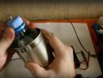
To assemble, you need to cut off the neck of the bottle so that it fits tightly into the tin can. A narrow, tall can, like condensed milk, is best. Two holes are made in the plastic cover, where you need to insert a steel wire. One of its edges is bent into a loop in the shape of the letter “C” so that it holds securely on the lid; the second end of the steel rod should not touch the can. Afterwards the lid is screwed on.
The KP302a gate leg is screwed to a loop of steel wire, and the tester terminals are connected to the drain and source. You need to wrap a copper wire around the can and secure one end to the black terminal. The capricious and short-lived field-effect transistor can be replaced, for example, by connecting several others using a Darlington circuit, the main thing is that the total gain must be equal to 9000.


The homemade dosimeter is ready, but it is needed calibrate. To do this, a laboratory radiation source is used; as a rule, the unit of its ion radiation is indicated on it.

Scheme No. 2 - installation of the meter
To assemble a dosimeter with your own hands, an ordinary one will do. counter SBM-20- you will have to buy it at a specialized radio parts store. An anode, a thin wire, passes along the axis through the sealed cathode tube. The internal space is filled with gas at low pressure, which creates an optimal environment for electrical breakdown.

The voltage of SBM-20 is about 300 - 500 V, it must be adjusted so as to prevent arbitrary breakdown. When a radioactive particle hits, it ionizes the gas in the tube, creating a large number of ions and electrons between the cathode and anode. Similarly, the counter is triggered for each particle.
It is important to know! For a homemade device, any meter designed for 400 volts is suitable, but the SBM-20 is the most suitable; you can purchase the popular STS-5, but it is less durable.
Dosimeter circuit consists of two blocks: an indicator and a network rectifier, which are assembled in plastic boxes and connected with a connector. The power supply is connected to the network for a short period of time. The capacitor is charged to a voltage of 600 W and is the power source for the device.

The unit is disconnected from the network and from the indicator, and connected to the connector contacts high impedance phones. A capacitor should be of good quality; this will extend the operating time of the dosimeter. A homemade device can function for 20 minutes or more.
Technical features:
- the rectifier resistor should be optimally selected with a power dissipation of up to 2 W;
- capacitors can be ceramic or paper, with the appropriate voltage;
- You can choose any counter;
- eliminate the possibility of touching the resistor contacts with your hands
Natural background radiation will be registered as rare signals in phones; the absence of sounds means that there is no power.
Scheme No. 3 with a two-wire detector
You can construct a homemade dosimeter with a two-wire detector; for this you need a plastic capacitor, a pass capacitor, three resistors and a single-channel damper.
The damper itself reduces the amplitude of oscillations and is installed behind the detector, directly next to the feed-through capacitor, which measures the dose. For this design only suitable resonant rectifiers, but expanders are practically not used. The device will be more sensitive to radiation, but will require more time to assemble.

There are other schemes on how to make a dosimeter yourself. Radio amateurs have developed and tested many variations, but most are based on the circuits described above.
Whether we like it or not, radiation has firmly entered our lives and is not going to go away. We need to learn to live with this phenomenon, which is both useful and dangerous. Radiation manifests itself as invisible and imperceptible radiation, and without special devices it is impossible to detect them.
A little history of radiation
X-rays were discovered in 1895. A year later, the radioactivity of uranium was discovered, also in connection with X-rays. Scientists realized that they were faced with completely new, hitherto unseen natural phenomena. It is interesting that the phenomenon of radiation was noticed several years earlier, but no importance was attached to it, although Nikola Tesla and other workers of the Edison laboratory also received burns from X-rays. Damage to health was attributed to anything, but not to rays, which living things had never encountered in such doses. At the very beginning of the 20th century, articles began to appear about the harmful effects of radiation on animals. This, too, was not given any importance until the sensational story with the “radium girls” - workers of a factory that produced luminous watches. They just wet the brushes with the tip of their tongue. The terrible fate of some of them was not even published, for ethical reasons, and remained a test only for the strong nerves of doctors.
In 1939, physicist Lise Meitner, who, together with Otto Hahn and Fritz Strassmann, belongs to the people who were the first in the world to divide the uranium nucleus, inadvertently blurted out about the possibility of a chain reaction, and from that moment a chain reaction of ideas about creating a bomb began, namely a bomb, and not at all “peaceful atom”, for which the bloodthirsty politicians of the 20th century, of course, would not have given a penny. Those who were “in the know” already knew what this would lead to and the atomic arms race began.
How did the Geiger-Müller counter appear?
 The German physicist Hans Geiger, who worked in the laboratory of Ernst Rutherford, in 1908 proposed the principle of operation of a “charged particle” counter as a further development of the already known ionization chamber, which was an electric capacitor filled with gas at low pressure. It was used by Pierre Curie in 1895 to study the electrical properties of gases. Geiger had the idea to use it to detect ionizing radiation precisely because these radiations had a direct effect on the degree of ionization of the gas.
In 1928, Walter Müller, under the leadership of Geiger, created several types of radiation counters designed to register various ionizing particles. The creation of counters was a very urgent need, without which it was impossible to continue the study of radioactive materials, since physics, as an experimental science, is unthinkable without measuring instruments. Geiger and Müller purposefully worked to create counters that were sensitive to each of the types of radiation that had been discovered: α, β and γ (neutrons were discovered only in 1932).
The Geiger-Muller counter proved to be a simple, reliable, cheap and practical radiation detector. Although it is not the most accurate instrument for studying specific types of particles or radiation, it is extremely suitable as an instrument for the general measurement of the intensity of ionizing radiation. And in combination with other detectors, it is used by physicists for precise measurements during experiments.
Ionizing radiation
To better understand the operation of a Geiger-Muller counter, it is helpful to have an understanding of ionizing radiation in general. By definition, these include anything that can cause ionization of a substance in its normal state. This requires a certain amount of energy. For example, radio waves or even ultraviolet light are not ionizing radiation. The border begins with “hard ultraviolet”, also known as “soft x-ray”. This type is a photon type of radiation. High-energy photons are usually called gamma quanta.
Ernst Rutherford was the first to divide ionizing radiation into three types. This was done in an experimental setup using a magnetic field in a vacuum. It later turned out that this is:
α - nuclei of helium atoms
β - high energy electrons
γ - gamma quanta (photons)
Later neutrons were discovered. Alpha particles are easily blocked even by ordinary paper, beta particles have a slightly greater penetrating power, and gamma rays have the highest penetrating power. Neutrons are the most dangerous (at a distance of up to many tens of meters in the air!). Due to their electrical neutrality, they do not interact with the electron shells of the molecules of the substance. But once they get into the atomic nucleus, the probability of which is quite high, they lead to its instability and decay, with the formation, as a rule, of radioactive isotopes. And those, in turn, decaying, themselves form the entire “bouquet” of ionizing radiation. The worst thing is that an irradiated object or living organism itself becomes a source of radiation for many hours and days.
The design of a Geiger-Muller counter and its operating principle

A Geiger-Muller gas-discharge counter is usually made in the form of a sealed tube, glass or metal, from which the air is evacuated, and instead an inert gas (neon or argon or a mixture of both) is added under low pressure, with an admixture of halogens or alcohol. A thin wire is stretched along the axis of the tube, and a metal cylinder is located coaxially with it. Both the tube and the wire are electrodes: the tube is the cathode, and the wire is the anode. A minus from a constant voltage source is connected to the cathode, and a plus from a constant voltage source is connected to the anode through a large constant resistance. Electrically, a voltage divider is obtained, at the middle point of which (the junction of the resistance and the anode of the meter) the voltage is almost equal to the voltage at the source. This is usually several hundred volts.
When an ionizing particle flies through the tube, the atoms of the inert gas, already in a high-intensity electric field, experience collisions with this particle. The energy given off by the particle during a collision is enough to separate electrons from gas atoms. The resulting secondary electrons are themselves capable of forming new collisions and, thus, a whole avalanche of electrons and ions is obtained. Under the influence of an electric field, electrons are accelerated towards the anode, and positively charged gas ions are accelerated towards the cathode of the tube. Thus, an electric current arises. But since the energy of the particle has already been spent on collisions, fully or partially (the particle flew through the tube), the supply of ionized gas atoms also ends, which is desirable and is ensured by some additional measures, which we will talk about when analyzing the parameters of the counters.
When a charged particle enters a Geiger-Muller counter, due to the resulting current, the resistance of the tube drops, and with it the voltage at the midpoint of the voltage divider, which was discussed above. Then the resistance of the tube, due to an increase in its resistance, is restored, and the voltage again becomes the same. Thus, we get a negative voltage pulse. By counting the impulses, we can estimate the number of passing particles. The electric field strength is especially high near the anode due to its small size, which makes the counter more sensitive.
Geiger-Muller counter designs
Modern Geiger-Muller counters are available in two main versions: “classic” and flat. The classic counter is made of a thin-walled metal tube with corrugation. The corrugated surface of the meter makes the tube rigid, resistant to external atmospheric pressure and does not allow it to wrinkle under its influence. At the ends of the tube there are sealing insulators made of glass or thermosetting plastic. They also contain terminal caps for connecting to the device circuit. The tube is marked and coated with a durable insulating varnish, not counting, of course, its terminals. The polarity of the terminals is also indicated. This is a universal counter for all types of ionizing radiation, especially beta and gamma.
 Counters sensitive to soft β-radiation are made differently. Due to the short range of beta particles, they have to be made flat, with a mica window that weakly blocks beta radiation; one of the options for such a counter is a radiation sensor BETA-2. All other properties of the meters are determined by the materials from which they are made.
Counters designed to record gamma radiation contain a cathode made of metals with a high charge number, or are coated with such metals. Gas is extremely poorly ionized by gamma photons. But gamma photons are capable of knocking out many secondary electrons from the cathode if it is chosen appropriately. Geiger-Muller counters for beta particles are made with thin windows to better transmit the particles, since they are ordinary electrons that have just received more energy. They interact with matter very well and quickly lose this energy.
In the case of alpha particles the situation is even worse. So, despite a very decent energy, on the order of several MeV, alpha particles interact very strongly with molecules in their path and quickly lose energy. If matter is compared to a forest, and an electron is compared to a bullet, then alpha particles will have to be compared to a tank crashing through a forest. However, a conventional counter responds well to α-radiation, but only at a distance of up to several centimeters.
For an objective assessment of the level of ionizing radiation dosimeters General purpose meters are often equipped with two counters operating in parallel. One is more sensitive to α and β radiation, and the second to γ rays. This scheme of using two counters is implemented in a dosimeter RADEX RD1008 and in a dosimeter-radiometer RADEKS MKS-1009, in which the counter is installed BETA-2 And BETA-2M. Sometimes a bar or plate of an alloy containing an admixture of cadmium is placed between the counters. When neutrons hit such a bar, γ-radiation is generated, which is recorded. This is done to be able to detect neutron radiation, to which simple Geiger counters are practically insensitive. Another method is to coat the housing (cathode) with impurities that can impart sensitivity to neutrons.
Halogens (chlorine, bromine) are added to the gas to quickly extinguish the discharge. Alcohol vapor also serves the same purpose, although alcohol in this case is short-lived (this is generally a feature of alcohol) and the “sobered up” meter constantly begins to “ring”, that is, it cannot work in the intended mode. This happens somewhere after 1e9 pulses (a billion) have been detected, which is not that much. Meters with halogens are much more durable.
Parameters and operating modes of Geiger counters
Sensitivity of Geiger counters.
The sensitivity of the counter is estimated by the ratio of the number of microroentgens from the reference source to the number of pulses caused by this radiation. Since Geiger counters are not designed to measure particle energy, accurate estimation is difficult. The counters are calibrated using reference isotope sources. It should be noted that this parameter can vary greatly for different types of counters; below are the parameters of the most common Geiger-Muller counters:
Geiger-Muller counter Beta-2- 160 ÷ 240 imp/µR
Geiger-Muller counter Beta-1- 96 ÷ 144 imp/µR
Geiger-Muller counter SBM-20- 60 ÷ 75 imp/µR
Geiger-Muller counter SBM-21- 6.5 ÷ 9.5 imp/µR
Geiger-Muller counter SBM-10- 9.6 ÷ 10.8 imp/μR
Entrance window area or work area
The area of the radiation sensor through which radioactive particles fly. This characteristic is directly related to the dimensions of the sensor. The larger the area, the more particles the Geiger-Muller counter will catch. Typically this parameter is indicated in square centimeters.
Geiger-Muller counter Beta-2- 13.8 cm 2
Geiger-Muller counter Beta-1- 7 cm 2
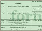
This voltage corresponds to approximately the middle of the operating characteristic. The operating characteristic is the flat part of the dependence of the number of recorded pulses on the voltage, which is why it is also called the “plateau”. At this point the highest operating speed is achieved (upper measurement limit). Typical value is 400 V.
Width of the counter operating characteristic.
This is the difference between the spark breakdown voltage and the output voltage on the flat part of the characteristic. Typical value is 100 V.
Slope of the meter operating characteristic.
The slope is measured as a percentage of pulses per volt. It characterizes the statistical error of measurements (counting the number of pulses). Typical value is 0.15%.
Permissible operating temperature of the meter.
For general purpose meters -50 ... +70 degrees Celsius. This is a very important parameter if the meter operates in chambers, channels, and other places of complex equipment: accelerators, reactors, etc.
Working resource of the counter.
The total number of pulses that the meter registers before its readings begin to become incorrect. For devices with organic additives, self-quenching is usually 1e9 (ten to the ninth power, or one billion). The resource is counted only if operating voltage is applied to the meter. If the counter is simply stored, this resource is not consumed.
Counter dead time.
This is the time (recovery time) during which the counter conducts current after being triggered by a passing particle. The existence of such a time means that there is an upper limit to the pulse frequency and this limits the measurement range. A typical value is 1e-4 s, which is ten microseconds.
It should be noted that due to dead time, the sensor may be “off scale” and remain silent at the most dangerous moment (for example, a spontaneous chain reaction in production). Such cases have happened, and to combat them, lead screens are used to cover part of the sensors of emergency alarm systems.
Custom counter background.
Measured in thick-walled lead chambers to assess the quality of meters. Typical value is 1 ... 2 pulses per minute.
Practical application of Geiger counters
Soviet and now Russian industry produces many types of Geiger-Muller counters. Here are some common brands: STS-6, SBM-20, SI-1G, SI21G, SI22G, SI34G, meters of the Gamma series, end counters of the series Beta"and there are many more. All of them are used for monitoring and measuring radiation: at nuclear industry facilities, in scientific and educational institutions, in civil defense, medicine, and even in everyday life. After the Chernobyl accident, household dosimeters, previously unknown to the population even by name, have become very popular. Many brands of household dosimeters have appeared. All of them use a Geiger-Muller counter as a radiation sensor. In household dosimeters, one to two tubes or end counters are installed.
UNITS OF MEASUREMENT OF RADIATION QUANTITIES
For a long time, the unit of measurement P (roentgen) was common. However, when moving to the SI system, other units appear. An x-ray is a unit of exposure dose, a "quantity of radiation", which is expressed as the number of ions produced in dry air. With a dose of 1 R in 1 cm3 of air, 2.082e9 pairs of ions are formed (which corresponds to 1 unit of charge of the SGSE). In the SI system, exposure dose is expressed in coulombs per kilogram, and with x-rays this is related to the equation:
1 C/kg = 3876 R
The absorbed dose of radiation is measured in joules per kilogram and is called Gray. This is a replacement for the outdated rad unit. The absorbed dose rate is measured in grays per second. Exposure dose rate (EDR), formerly measured in roentgens per second, is now measured in amperes per kilogram. The equivalent radiation dose at which the absorbed dose is 1 Gy (gray) and the radiation quality factor is 1 is called Sievert. The rem (biological equivalent of an x-ray) is a hundredth of a sievert, now considered obsolete. Nevertheless, even today all outdated units are very actively used.
The main concepts in radiation measurements are dose and power. Dose is the number of elementary charges in the process of ionization of a substance, and power is the rate of dose formation per unit time. And in what units this is expressed is a matter of taste and convenience.
Even a minimal dose is dangerous in terms of long-term consequences for the body. The calculation of danger is quite simple. For example, your dosimeter shows 300 milliroentgen per hour. If you stay in this place for a day, you will receive a dose of 24 * 0.3 = 7.2 roentgens. This is dangerous and you need to leave here as soon as possible. In general, if you detect even weak radiation, you need to move away from it and check it even from a distance. If she “follows you”, you can be “congratulated”, you have been hit by neutrons. But not every dosimeter can respond to them.
For radiation sources, a quantity characterizing the number of decays per unit of time is used; it is called activity and is also measured by many different units: curie, becquerel, rutherford and some others. The amount of activity, measured twice with a sufficient separation in time, if it decreases, makes it possible to calculate the time, according to the law of radioactive decay, when the source becomes sufficiently safe.
Typically, dosimeter circuits are assembled using microcontrollers or simple logic chips. But in many cases we only need a simple dosimeter. In the framework of this article, we will consider two elementary designs of radioactive radiation detectors, assembled with our own hands, in which the most complex component is the most common Geiger counter SBM-20.
|
The simplest dosimeter with a photodiode sensor |
Any radio amateur can assemble a simple Geiger counter with his own hands, which uses a conventional photodiode as a radiation detector instead of the SBM-20. The dosimeter is capable of detecting only alpha and beta radiation. Unfortunately, it will not be able to detect the X-ray range. The device circuit is assembled on a small printed circuit board and placed in a suitable housing. Copper tubing and foil are needed to filter out RF interference.

List of required radio components
BPW34 photodiode, LM358 operational amplifier, transistors 2N3904, 2N7000; capacitors 100 nF (2 pcs), 100 µF, 10 nF, 20 nF; Resistors 10 MΩ, 1.5 MΩ (2 pcs), 56 kΩ resistor, 150 kΩ, 1 kΩ (2 pcs), 250 kΩ potentiometer; Piezo speaker, Toggle switch
After assembly, check that the polarity of the speaker and LED are connected correctly. Place copper tubes and electrical tape on the photodiode. They should fit very tightly.

We drill a hole in the side of the aluminum case for the power switch, and on top for the photosensor, LED and sensitivity control. After installing the radio components, insert the batteries. Wrap electrical tape around the copper tubes to keep them in place. This will also reduce the number of light quanta affecting the photodiode.
You can check the performance of the resulting device using any test radiation source, which should be in special laboratories or in school physics classrooms. Or ride a bike to the Chernobyl zone.
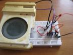
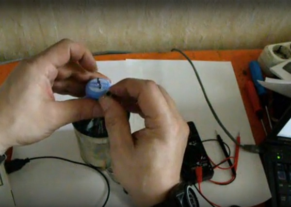
Simple dosimeter on SBM-20 |
To simplify the design, the device will be powered from a standard 220 volt AC mains

The high voltage comes from a doubler built on diodes and capacitors, then it goes to the Geiger counter SBM 20. Resistance R1 is connected in series with it. With each passage of a radiation particle through the counter, an electrical pulse is generated at its output and, accordingly, at resistor R1, which through resistor R2 enters the sound-emitting device, resulting in a click being heard.
Under normal background radiation, such clicks are heard 1-2 times per second. As the radiation level increases, the frequency of clicks increases greatly and can even turn into a continuous crackling sound.
A significant drawback of this DIY design is the fact that it is connected to the electrical network. Therefore, let's consider another option.
|
Simple dosimeter on SBM-20 with autonomous power supply |
In this radiation indicator device, a conventional blocking generator, a low-power transistor generator, is used as a high-voltage source. The alternating voltage from the secondary step-up winding of the transformer is rectified and supplied to the Geiger counter.

The transformer is manufactured on a ferrite ring with a diameter of 16 mm. Then we uniformly wind the primary winding with 400 turns of copper wire PEV 0.12. Next, using a PEV wire with a diameter of 0.42 mm, we twist the second and third windings of 8 and 3 turns, respectively.
In a properly assembled design, the voltage across capacitance C3 should be about 400 volts. If suddenly it is less, then it is necessary to swap the ends of the step-up winding. If the voltage is completely absent, then you need to swap the terminals of the third winding.
|
Radiation safety |
In connection with the environmental consequences of atomic explosions for peaceful purposes on Novaya Zemlya and in the region of the Semipalatinsk test site, due to the discharge of radioactive waste into the Techa River in the Southern Urals (1949-1956), especially due to environmental pollution during the operation of nuclear power plants (Chernobyl accident, 1986 and others), the study of the fundamentals of radiation safety and radiation dosimetry has become very relevant today. The population has developed radiophobia, i.e. fear of radiation even in the smallest doses, much less than any scientifically proven degree of risk.
Here BD1 is an ionizing radiation sensor - a Geiger counter of the SBM20 type. The high voltage at its anode forms a blocking generator (VT1, T1, etc.). On the step-up winding I of transformer T1, voltage pulses periodically occur with a frequency of several hertz (f ≈ 1/R6C5), the amplitude of which is close to Uimp = (U C6 - 0.5) n 1 / n 2 = (9 - 0.5) 420/8 ≈ 450 V (U C6 ≈ 9 V is the supply voltage of the blocking generator, 0.5 V is the pulse saturation voltage of the KT3117A transistor; n 1 and n 2 are the number of turns in windings I and II of transformers). These pulses, through diodes VD1 and VD2, charge capacitor C1, which thus becomes the power source for the Geiger counter. Diode VD3, damping the reverse voltage pulse on winding II, prevents the blocking oscillator from switching to the mode of a much higher frequency LC oscillator.
When a Geiger counter is excited by a β-particle or a γ-quantum, a current pulse with a short rise and a long fall appears in it. Accordingly, a voltage pulse of the same shape appears at its anode. Its amplitude is at least 50 V.
The purpose of the single-vibrator, made on elements DD1.1 and DD1.2, is to convert the pulse taken from the anode of the Geiger counter into a “rectangular” pulse of a digital standard with a duration timp ≈ 0.7 R4 C3 = 0.7 10 6 0 .01 10 -6 = 7 ms. In its formation, resistor R2 plays an important role - it limits the current in the protective diodes of the microcircuit to a value at which the “zero” voltage at input 8 of DD1.1 remains within .
This 7-millisecond “single” pulse arrives at input 6 of the multivibrator, made on elements DD1.3 and DD1.4, and creates the conditions necessary for its self-excitation. The multivibrator is excited at a frequency F ≈ 1/2 0.7 R7 C7 = 1/2 0.7 51 10 3 0.01 10 -6 = 1400 Hz, and a piezo emitter connected to its outputs in phase transforms this excitation into a short acoustic click.
The printed circuit board of the indicator is made of double-sided foil fiberglass laminate with a thickness of 1.5 mm. In Fig. a shows its mounting side, and in fig. b - configuration of the foil under the parts (null foil).

Almost all resistors in the indicator are MLT-0.125 (R1 - KIM-0.125). Capacitors: C1 - K73-9; S2 - KD-26; SZ, S7 and S8 -KM-6 or K10-17-2b; C4 and C6 - K50-40 or K50-35; C5 - K53-30. Black squares in Fig. b shows the connections of their “grounded” terminals with the null foil; black squares with a light dot in the center - connections with the null foil of some fragments of the printed circuit and pin 7 of the microcircuit.
The SBM20 meter is fixed in the desired position using contact stands, which can be made, for example, from paper clips. They are pressed onto the meter terminals and soldered to the printed circuit board (for strength - on both sides).

To avoid overheating that may occur when soldering thick steel wire, it is recommended to use a good flux.
 Transformer T1 is wound on a ring core M3000NM (nickel-manganese ferrite) of standard size K16 x 10 x 4.5 mm (external diameter x internal diameter x height). The sharp edges of the core are smoothed with sandpaper and covered with electrically and mechanically strong insulation, for example, wrapped with thin Mylar or fluoroplastic tape.
Winding I is wound first; it contains 420 turns of PEV-2-0.07 wire. The winding is carried out almost turn to turn, in one direction, leaving a gap of 1...2 mm between its beginning and end. Winding I is covered with a layer of insulation and winding II is wound on top - 8 turns of wire with a diameter of 0.15...0.2 mm in any insulation - and winding III - 3 turns of the same wire. Windings II and III should be distributed throughout the core as evenly as possible. The location of the windings and their terminals must correspond to the design of the printed circuit board, and their phasing - indicated on the circuit diagram (the in-phase ends of the windings - entering the core hole on one side - are indicated by dots).
The manufactured transformer is covered with a layer of waterproofing, for example, wrapped with a narrow strip of adhesive PVC tape. The transformer is secured to the board with an M3 screw using two elastic (non-squeezable windings) washers (Fig.).
The mounted board is mounted on the front panel (Fig.), made of impact-resistant polystyrene 2 mm thick, to which a corner-enclosure is glued to accommodate Corundum (to avoid the consequences of depressurization, it is not recommended to place power supplies directly in the electronic part of the devices). On this corner strips of the same polystyrene are glued, between which a printed circuit board is inserted. The board is secured with an M2 screw to a support stand glued to the front panel.

A hole with a diameter of 30 mm is cut out in the front panel for the ZP-1 piezo emitter (ZP-1 can be glued into the socket thus formed or fixed in it in some other way).
From the outside, this hole can be closed with a decorative grille. A PD9-1 type power switch is also located on the front panel.
The fully assembled front panel is inserted into the device body - a box of appropriate dimensions, made of the same polystyrene. In the wall of the housing adjacent directly to the Geiger counter, it is necessary to cut a rectangular hole measuring 10 x 85 mm, which, in order to avoid attenuation of the controlled radiation (table), can be blocked only with a sparse grating.
|
Material |
Thickness, mm |
Attenuation ratio |
| Duralumin | ||
| Foil fiberglass | ||
| Impact resistant polystyrene | ||
| PVC electrical tape |
0,25 |
|
| Polyethylene film |
0,05 |
|
| Aluminium foil |
0,02 |
1,02 |
About possible replacements.
The SBM20 meter is available in three modifications, differing only in the design of the terminals. The previously produced STS5 meter is also close in its characteristics to the SBM20.
The ZP-1 piezo emitter can also be replaced: the ZP-22 emitter, which has the same dimensions, is practically in no way inferior to it.
The blocking oscillator can use any mid-frequency silicon transistor that has a pulse saturation voltage of no higher than 0.5 V (at a collector current of 1...2 A) and a current gain of at least 50.
Diodes VD1 and VD2 can be replaced with a KTs111A pole. For any other replacements, you need to pay attention to the reverse current of the diode - it should not exceed 0.1 μA. Otherwise, the radiation indicator, having lost its energy efficiency, will turn into a very ordinary device.
The indicator converts a short-term current pulse generated in a Geiger counter under the influence of an ionizing particle into an acoustic click. And if the response of the SBM20 counter to the natural background radiation is, say, 18...25 pulses per minute, then this is exactly the clicking sound of the device that its owner will hear. If it approaches the radiation source so much that the intensity of the ionizing radiation field, for example, doubles, then the frequency of these clicks will also double.