Connection lm317 with adjustment. Voltage stabilizer on LM317. Pinout of the microcircuit and transistor
Quite often there is a need for a simple voltage stabilizer. This article provides a description and examples of the use of an inexpensive (prices for LM317) integrated voltage stabilizer LM317.
The list of tasks solved by this stabilizer is quite extensive - this includes powering various electronic circuits, radio devices, fans, motors and other devices from the mains or other voltage sources, such as a car battery. The most common circuits are voltage-regulated.
In practice, with the participation of LM317, you can build a voltage stabilizer for an arbitrary output voltage in the range of 3...38 volts.
Specifications:
- Stabilizer output voltage: 1.2... 37 volts.
- Load-bearing current up to 1.5 amperes.
- Stabilization accuracy 0.1%.
- There is internal protection against accidental short circuit.
- Excellent protection of the integrated stabilizer from possible overheating.

Power dissipation and input voltage of the LM317 stabilizer
The voltage at the stabilizer input should not exceed 40 volts, and there is also one more condition - the minimum input voltage should exceed the desired output voltage by 2 volts.
The LM317 microcircuit in the TO-220 package is capable of stable operation at a maximum load current of up to 1.5 amperes. If you do not use a high-quality heat sink, this value will be lower. The power released by the microcircuit during its operation can be determined approximately by multiplying the output current and the difference between the input and output potential.

The maximum permissible power dissipation without a heat sink is approximately 1.5 W at an ambient temperature of 30 degrees Celsius or less. If good heat dissipation from the LM317 case is ensured (no more than 60 g), the power dissipation can be 20 watts.
When placing a microcircuit on a radiator, it is necessary to isolate the microcircuit body from the radiator, for example, with a mica gasket. It is also advisable to use heat-conducting paste for effective heat removal.
Selection of resistance for stabilizer LM317
For accurate operation of the microcircuit, the total value of resistances R1...R3 must create a current of approximately 8 mA at the required output voltage (Vo), that is:
R1 + R2 + R3 = Vo / 0.008
This value should be taken as ideal. In the process of selecting resistances, a slight deviation (8...10 mA) is allowed.
The value of variable resistance R2 is directly related to the output voltage range. Typically, its resistance should be approximately 10...15% of the total resistance of the remaining resistors (R1 and R2), or you can select its resistance experimentally.
The location of the resistors on the board can be arbitrary, but for better stability it is advisable to place it away from the heatsink of the LM317 chip.
Circuit stabilization and protection
Capacitance C2 and diode D1 are optional. The diode protects the LM317 stabilizer from possible reverse voltage that appears in the designs of various electronic devices.
Capacitance C2 not only slightly reduces the response of the LM317 microcircuit to voltage changes, but also reduces the influence of electrical interference when the stabilizer board is placed near places with powerful electromagnetic radiation.
The adjustable voltage stabilizer LM317 is available in monolithic packages TO-220, TO-220FP, TO-3, D 2 PAK. The microcircuit is designed for an output current of 1.5 A, with an adjustable output voltage in the range from 1.2 to 37 V. The nominal output voltage is selected using a resistive divider.
Key Features of LM317
- Maximum input voltage 40V
- Output voltage range 1.2 to 37V
- Output current 1.5 A
- Load instability 0.1%
- Current limit
- Thermal shutdown
- Operating temperature 0 to 125 o C
- Storage temperature -65 to 150 o C
Analogue LM317
The domestic analogue of LM317 is the KP142EH12A chip.
Pin Configuration

The circuit of the regulated power supply on LM317 will look like this:

Transformer power 40-50 W, secondary winding voltage 20-25 volts. Diode bridge 2-3 A, capacitors 50 volts. C4 - tantalum, if this is not available, you can use a 25 uF electrolyte. Variable resistor R2 allows you to adjust the output voltage from 1.3 volts; the upper limit of the output voltage will depend on the voltage of the secondary winding of the transformer. The input of the LM317 stabilizer should be no more than 40 volts; the maximum output voltage will be 3 volts less than the input. Diodes VD1 and VD2 serve to protect the LM317 in some situations.
If a power supply with a fixed voltage is required, then the variable resistor R2 must be replaced with a constant one, the value of which can be calculated using the LM317 calculator or using the formula from the LM317 datasheet.

You can assemble a current stabilizer on the LM317 chip; the value and power of resistor R1 is calculated using the LM317 calculator. This circuit is used as a power source for high-power LEDs.
Charger for LM317 (circuit from datasheet)

This charger circuit is designed for 6 volt batteries, but by selecting R2 you can set the desired output voltage for other batteries. With a rating of R3 equal to 1 Ohm, the charging current limitation will be at 0.6 A.
The current at the output of the power supply may increase due to a decrease in the load resistance (a simple example, a short circuit), and a change in the load current occurs due to a change in its supply voltage. The current stabilizer on lm317 ensures current stability (current limitation) at the output in the cases described above.
This stabilizer can be used in power supply circuits for LEDs, chargers, laboratory power supplies, and so on.
If, for example, we consider LEDs, then it is necessary to take into account the fact that for them it is necessary to limit the current, not the voltage. You can apply 12V to the crystal and it will not burn out, provided that the current is limited to the rated value (depending on the marking and type of LED).
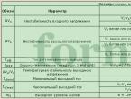
Main technical characteristicsLM317
Maximum output current 1.5A
Maximum input voltage 40V
Output voltage from 1.2V to 37V
More detailed characteristics and graphs can be found in the stabilizer.
Current stabilizer circuit for lm317
The advantage of this stabilizer is that it is linear and does not introduce high-frequency interference, for example, like some switching stabilizers. The downside is the low efficiency (due to its linearity), and therefore significant heating of the chip crystal occurs. As you already understand, the microcircuit must be provided with a good heatsink.
Resistor R1 is responsible for the amount of stabilization (limiting) current. Using this resistor, you can set the stabilization current, for example, 100mA, then even with a short circuit, a current of 100mA will flow at the output of the circuit.
The resistance of resistor R1 is calculated by the formula:
R1=1.2/Iload
Initially, it is necessary to determine the amount of stabilization current. For example, I need to limit the current consumption of LEDs to 100mA. Then,
R1=1.2/0.1A=12 Ohm.
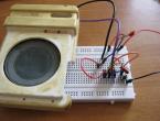
That is, to limit the current to 0.1A, it is necessary to install resistor R1 = 12 Ohms. Let's check it on hardware... To test it, I assembled the circuit on a breadboard. I was too lazy to look for a 12 Ohm resistor, so I connected two 22 Ohm ones in parallel (we had them on hand).
I set the idle voltage to 12V (you can set it to any voltage). After which, I shorted the output to ground, and the LM317 stabilizer limited the current to 0.1A. The calculations were confirmed.
As the voltage increases or decreases, the current remains stable.
The resistor can be soldered to the terminals of the microcircuit, but do not forget that the entire load current flows through the resistor, so at high currents a higher power resistor is needed.
If you use this current stabilizer on LM317 in a laboratory power supply, then you need to install a wire-type variable resistor; a simple variable resistor will not withstand the load currents flowing through it.
For the lazy, I present a table of resistor R1 values depending on the required stabilization current.
| Current | R1 (standard) |
| 0.025 | 51 Ohm |
| 0.05 | 24 ohm |
| 0.075 | 16 ohm |
| 0.1 | 13 ohm |
| 0.15 | 8.2 Ohm |
| 0.2 | 6.2 Ohm |
| 0.25 | 5.1 Ohm |
| 0.3 | 4.3 Ohm |
| 0.35 | 3.6 Ohm |
| 0.4 | 3 Ohm |
| 0.45 | 2.7 Ohm |
| 0.5 | 2.4 Ohm |
| 0.55 | 2.2 Ohm |
| 0.6 | 2 Ohm |
| 0.65 | 2 Ohm |
| 0.7 | 1.8 Ohm |
| 0.75 | 1.6 Ohm |
| 0.8 | 1.6 Ohm |
| 0.85 | 1.5 Ohm |
| 0.9 | 1.3 Ohm |
| 0.95 | 1.3 Ohm |
| 1 | 1.3 Ohm |
Thus, using a biscuit switch and several resistors, you can assemble an adjustable current stabilizer circuit with fixed values.
LM317 is a low cost IC Voltage regulator With built-in protection against output short circuit and overheating, an easy-to-assemble linear DC voltage regulator can be made on the LM317, which can be adjustable. Such microcircuits come in different packages, for example TO-220 or TO-92. If the hull is TO-92, then the last two letters of the name will be LZ i.e. so: LM317LZ, the pinouts of this microcircuit differ in different cases, so you need to be more careful, there are also such microcircuits in SMD packages. You can order LM317LZ in bulk in a small batch at the link: LM317LZ (10 pcs.), LM317T at the link: LM317T (10 pcs.). Consider the stabilizer circuit:
Figure 1 - DC voltage stabilizer on the LM317LZ chip
In addition to the microcircuit, this stabilizer contains 4 more parts; resistor R2 regulates the voltage at the output of the stabilizer. For ease of assembly, you can use the following diagram:

Figure 2 - DC voltage stabilizer on the LM317LZ chip
All DC voltage stabilizers are divided into 2 types:
1) linear (as for example in our case, i.e. on LM317),
2) pulsed (with higher efficiency and for more powerful loads).
The operating principle of linear (not all) stabilizers can be understood from the figure:
Figure 3 - Operating principle of a linear stabilizer
From Figure 3 it is clear that such a stabilizer is a divider, the lower arm of which is the load and the upper arm is the microcircuit itself. The input voltage changes and the microcircuit changes its resistance so that the output voltage remains unchanged. Such stabilizers have low efficiency because some of the energy is lost on the chip. Switching stabilizers are also a divider, only their upper (or lower) arm can either have a very low resistance (open key) or very high (private key), alternating such states creates PWM with a high frequency and the voltage at the load is smoothed by a capacitor (and/ or the current is smoothed by a choke), thus creating high efficiency, but due to the high PWM frequency, switching stabilizers create electromagnetic interference. There are also linear stabilizers in which the element that carries out stabilization is placed parallel to the load - in such cases, this element is usually a zener diode and in order for stabilization to be carried out, current is supplied to this parallel connection from a current source, the current source is made by installing a resistor with a high resistance in series with the voltage source , if voltage is applied directly to such a stabilizer, there will be no stabilization and the zener diode will most likely burn out.

If you decide to convert your car to LED lighting, you will need at least an lm317 current stabilizer for LEDs. Assembling a basic stabilizer is not at all difficult, but in order to avoid disastrous mistakes even with such a simple task, a minimal educational program will not hurt. Many people not involved in radio electronics often confuse concepts such as current stabilizer and voltage stabilizer.
Easy about simple things. Current strength, voltage and their stabilization
Voltage determines how quickly electrons move through a conductor. Many passionate fans of hard computer overclocking increase the voltage of the central processor core, making it start to function faster.
Current strength is the density of electron movement within an electrical conductor. This parameter is extremely important for radioelements operating on the principle of thermionic secondary emission, in particular, light sources. If the cross-sectional area of the conductor is not able to pass the flow of electrons, excess current begins to be released in the form of heat, causing significant overheating of the part.
To better understand the process, let’s analyze the plasma arc (electric ignition of gas stoves and boilers works on its basis). At very high voltages, the speed of free electrons is so high that they can easily “fly” the distance between the electrodes, forming a plasma bridge.

And this is an electric heater. When electrons pass through it, they transfer their energy to the heating element. The higher the current, the denser the flow of electrons, the more the thermoelement heats up.
Why is current and voltage stabilization necessary?
Any radio-electronic component, be it a light bulb or a computer's central processor, requires for optimal operation a clearly limited number of electrons that flow through the conductors.
Since our article is about a stabilizer for LEDs, we’ll talk about them.
With all their advantages, LEDs have one drawback - high sensitivity to power parameters. Even moderate excess of force and voltage can lead to burnout of the light-emitting material and failure of the diode.
Nowadays it is very fashionable to remodel a car's lighting system for LED lighting. Their color temperature is much closer to natural light than that of xenon and incandescent lamps, which makes the driver much less tired on long trips.
However, this solution requires a special technical approach. The rated supply current of a car LED diode is 0.1-0.15 mA, and the starting battery current is hundreds of amperes. This is enough to burn out a lot of expensive lighting elements. To avoid this, use a 12 volt stabilizer for LEDs in cars.
The amperage in a vehicle network is constantly changing. For example, a car air conditioner “eats” up to 30 amperes; when it is turned off, the electrons “allocated” to its operation will no longer return back to the generator and battery, but will be redistributed among other electrical appliances. If an additional 300 mA does not play a role in an incandescent lamp rated at 1-3 A, then several such jumps can be fatal for a diode with a supply current of 150 mA.
To guarantee long-term operation of automotive LEDs, a current stabilizer based on lm317 is used for high-power LEDs.
Types of stabilizers
According to the method of limiting the current, there are two types of devices:
- Linear;
- Pulse.

It works on the principle of a voltage divider. It releases a current of a given parameter, dissipating the excess in the form of heat. The operating principle of such a device can be compared to a watering can equipped with an additional drain hole.
Advantages
- affordable price;
- simple installation diagram;
- easy to assemble with your own hands.
Disadvantage: due to heating, it is poorly suited to work with heavy loads.
Like a vegetable cutter, it cuts the incoming current through a special cascade, giving out a strictly dosed amount.

Advantages
- designed for high loads;
- does not heat up during operation.
Flaws
- requires a power source for its own operation;
- creates electromagnetic radiation;
- relatively high price;
- Difficult to make yourself.
Considering the low current in car LEDs, you can assemble a simple stabilizer for LEDs with your own hands. The most affordable and simple driver for LED lamps and strips is assembled on the lm317 chip.
Brief description of lm317
The LM317 radio-electronic module is a microcircuit used in current and voltage stabilization systems.
- The voltage stabilization range from 1.7 to 37 V will ensure stable LED brightness, independent of engine speed;
- Support for output current up to 1.5 A allows you to connect several photo emitters;
- High stability allows fluctuations in output parameters of only 0.1% of the nominal value;
- Has built-in current limiting protection and a shutdown cascade for overheating;
- The microcircuit body is ground, so when fastened with a self-tapping screw to the car body, the number of mounting wires is reduced.
Application area
- Voltage and current stabilizer for LEDs in domestic conditions (including for LED strips);
- Voltage and current stabilizer for LEDs in cars;
Current stabilizer circuits for LEDs
 Circuit of the simplest stabilizer
 The simplest 12 volt voltage stabilizer can be assembled using this circuit. Resistor R1 limits the output current, R2 limits the output voltage. The capacitors used in this circuit reduce voltage ripple and increase operating stability.
The needs of the motorist will be satisfied by the simplest stabilization mechanism, since the supply voltage in the car network is quite stable.
To make a stabilizer for diodes in a car you will need:
- Chip lm317;
- Resistor as a current regulator for LEDs;
- Soldering and installation tools.
We assemble according to the above diagram
Calculation of a resistor for an LED driver
The power and resistance of the resistor are calculated based on the current strength of the power supply and the current required by the LEDs. For an automotive LED with a power of 150 mA, the resistor resistance should be 10-15 Ohms, and the calculated power should be 0.2-0.3 W.
How to assemble it yourself, watch the video:
The availability and simplicity of the driver design on the lm317 chip allows you to painlessly re-equip the electric lighting systems of any car.