Voltage converter based on a field-effect transistor. Low voltage voltage converters for LEDs Low voltage converters for powering LEDs
Flashlight on a current source, with automatic equalization of current in LEDs, so that LEDs can have any range of parameters (LED VD2 sets the current, which is repeated by transistors VT2, VT3, so the currents in the branches will be the same)
The transistors, of course, should also be the same, but the spread of their parameters is not so critical, so you can take either discrete transistors, or if you can find three integrated transistors in one package, their parameters are as identical as possible. Play around with the placement of the LEDs, you need to choose an LED-transistor pair so that the output voltage is minimal, this will increase the efficiency.
The introduction of transistors leveled out the brightness, however, they have resistance and the voltage drops across them, which forces the converter to increase the output level to 4V. To reduce the voltage drop across the transistors, you can propose the circuit in Fig. 4, this is a modified current mirror, instead of the reference voltage Ube = 0.7V in the circuit in Fig. 3, you can use the 0.22V source built into the converter, and maintain it in the VT1 collector using an op-amp, also built into the converter.

Rice. 4.Flashlight on a current source, with automatic current equalization in LEDs, and with improved efficiency
Because The op-amp output is of the “open collector” type; it must be “pulled up” to the power supply, which is done by resistor R2. Resistances R3, R4 act as a voltage divider at point V2 by 2, so the opamp will maintain a voltage of 0.22*2 = 0.44V at point V2, which is 0.3V less than in the previous case. It is not possible to take an even smaller divider in order to lower the voltage at point V2. a bipolar transistor has a resistance Rke and during operation the voltage Uke will drop on it, in order for the transistor to work correctly V2-V1 must be greater than Uke, for our case 0.22V is quite enough. However, bipolar transistors can be replaced with field-effect transistors, in which the drain-source resistance is much lower, this will make it possible to reduce the divider, so as to make the difference V2-V1 very insignificant.
Throttle.The choke must be taken with minimal resistance, special attention should be paid to the maximum permissible current; it should be about 400 -1000 mA.
The rating doesn't matter as much as the maximum current, so Analog Devices recommends something between 33 and 180 µH. In this case, theoretically, if you do not pay attention to the dimensions, then the greater the inductance, the better in all respects. However, in practice this is not entirely true, because we do not have an ideal coil, it has active resistance and is not linear, in addition, the key transistor at low voltages will no longer produce 1.5A. Therefore, it is better to try several coils of different types, designs and different ratings in order to choose the coil with the highest efficiency and the lowest minimum input voltage, i.e. a coil with which the flashlight will glow for as long as possible.
Capacitors.C1 can be anything. It is better to take C2 with tantalum because It has low resistance, which increases efficiency.
Schottky diode.Any for current up to 1A, preferably with minimal resistance and minimal voltage drop.
Transistors.Any with a collector current of up to 30 mA, coefficient. current amplification of about 80 with a frequency of up to 100 MHz, KT318 is suitable.
LEDs.You can use white NSPW500BS with a glow of 8000 mcd from Power Light Systems.
Voltage transformerADP1110, or its replacement ADP1073, to use it, the circuit in Fig. 3 will need to be changed, take a 760 µH inductor, and R1 = 0.212/60mA = 3.5 Ohm.
Flashlight on ADP3000-ADJ
Options:
Power supply 2.8 - 10 V, efficiency approx. 75%, two brightness modes - full and half.
The current through the diodes is 27 mA, in half-brightness mode - 13 mA.
In order to obtain high efficiency, it is advisable to use chip components in the circuit.
A correctly assembled circuit does not need adjustment.
The disadvantage of the circuit is the high (1.25V) voltage at the FB input (pin 8).
Currently, DC/DC converters with an FB voltage of about 0.3V are produced, in particular from Maxim, on which it is possible to achieve an efficiency above 85%.

Flashlight diagram for Kr1446PN1.

Resistors R1 and R2 are a current sensor. Operational amplifier U2B - amplifies the voltage taken from the current sensor. Gain = R4 / R3 + 1 and is approximately 19. The gain required is such that when the current through resistors R1 and R2 is 60 mA, the output voltage turns on transistor Q1. By changing these resistors, you can set other stabilization current values.
In principle, there is no need to install an operational amplifier. Simply, instead of R1 and R2, one 10 Ohm resistor is placed, from it the signal through a 1 kOhm resistor is supplied to the base of the transistor and that’s it. But. This will lead to a decrease in efficiency. On a 10 Ohm resistor at a current of 60 mA, 0.6 Volt - 36 mW - is dissipated in vain. If an operational amplifier is used, the losses will be:
on a 0.5 Ohm resistor at a current of 60 mA = 1.8 mW + consumption of the op-amp itself is 0.02 mA let at 4 Volts = 0.08 mW
= 1.88 mW - significantly less than 36 mW.
About the components.
Any low-power op-amp with a low minimum supply voltage can work in place of the KR1446UD2; the OP193FS would be better suited, but it is quite expensive. Transistor in SOT23 package. A smaller polar capacitor - type SS for 10 Volts. The inductance of CW68 is 100 μH for a current of 710 mA. Although the cutoff current of the inverter is 1 A, it works fine. It achieved the best efficiency. I selected the LEDs based on the most equal voltage drop at a current of 20 mA. The flashlight is assembled in a housing for two AA batteries. I shortened the space for the batteries to fit the size of AAA batteries, and in the freed-up space I assembled this circuit using wall-mounted installation. A case that fits three AA batteries works well. You will need to install only two, and place the circuit in place of the third.
Efficiency of the resulting device.
Input U I P Output U I P Efficiency
Volt mA mW Volt mA mW %
3.03 90 273 3.53 62 219 80
1.78 180 320 3.53 62 219 68
1.28 290 371 3.53 62 219 59
Replacing the bulb of the "Zhuchek" flashlight with a module from the companyLuxeonLumiledLXHL-NW 98.
We get a dazzlingly bright flashlight, with a very light press (compared to a light bulb).


Rework scheme and module parameters.
StepUP DC-DC converters ADP1110 converters from Analog devices.


Power supply: 1 or 2 1.5V batteries, operability maintained up to Uinput = 0.9V
Consumption:
*with switch open S1 = 300mA
*with switch closed S1 = 110mA
LED Electronic Flashlight
Powered by just one AA or AAA AA battery on a microcircuit (KR1446PN1), which is a complete analogue of the MAX756 (MAX731) microcircuit and has almost identical characteristics.

The flashlight is based on a flashlight that uses two AA size AA batteries as a power source.
The converter board is placed in the flashlight instead of the second battery. A contact made of tinned sheet metal is soldered at one end of the board to power the circuit, and at the other there is an LED. A circle made of the same tin is placed on the LED terminals. The diameter of the circle should be slightly larger than the diameter of the reflector base (0.2-0.5 mm) into which the cartridge is inserted. One of the diode leads (negative) is soldered to the circle, the second (positive) goes through and is insulated with a piece of PVC or fluoroplastic tube. The purpose of the circle is twofold. It provides the structure with the necessary rigidity and at the same time serves to close the negative contact of the circuit. The lamp with the socket is removed from the lantern in advance and a circuit with an LED is placed in its place. Before installation on the board, the LED leads are shortened in such a way as to ensure a tight, play-free fit. Typically, the length of the leads (excluding soldering to the board) is equal to the length of the protruding part of the fully screwed-in lamp base.
The connection diagram between the board and the battery is shown in Fig. 9.2.
Next, the lantern is assembled and its functionality is checked. If the circuit is assembled correctly, then no settings are required.
The design uses standard installation elements: capacitors of the K50-35 type, EC-24 chokes with an inductance of 18-22 μH, LEDs with a brightness of 5-10 cd with a diameter of 5 or 10 mm. Of course, it is possible to use other LEDs with a supply voltage of 2.4-5 V. The circuit has sufficient power reserve and allows you to power even LEDs with a brightness of up to 25 cd!
About some test results of this design.
The flashlight modified in this way worked with a “fresh” battery without interruption, in the on state, for more than 20 hours! For comparison, the same flashlight in the “standard” configuration (that is, with a lamp and two “fresh” batteries from the same batch) worked for only 4 hours.
And one more important point. If you use rechargeable batteries in this design, it is easy to monitor the state of their discharge level. The fact is that the converter on the KR1446PN1 microcircuit starts stably at an input voltage of 0.8-0.9 V. And the glow of the LEDs is consistently bright until the voltage on the battery reaches this critical threshold. The lamp will, of course, still burn at this voltage, but we can hardly talk about it as a real light source.
Rice. 9.2Figure 9.3


The printed circuit board of the device is shown in Fig. 9.3, and the arrangement of elements is in Fig. 9.4.
Turning the flashlight on and off with one button
The circuit is assembled using a CD4013 D-trigger chip and an IRF630 field-effect transistor in the “off” mode. the current consumption of the circuit is practically 0. For stable operation of the D-trigger, a filter resistor and capacitor are connected to the input of the microcircuit; their function is to eliminate contact bounce. It is better not to connect unused pins of the microcircuit anywhere. The microcircuit operates from 2 to 12 volts; any powerful field-effect transistor can be used as a power switch, because The drain-source resistance of the field-effect transistor is negligible and does not load the output of the microcircuit.
CD4013A in SO-14 package, analogue of K561TM2, 564TM2

Simple generator circuits.
Allows you to power an LED with an ignition voltage of 2-3V from 1-1.5V. Short pulses of increased potential unlock the p-n junction. The efficiency of course decreases, but this device allows you to “squeeze” almost its entire resource from an autonomous power source.
Wire 0.1 mm - 100-300 turns with a tap from the middle, wound on a toroidal ring.


LED flashlight with adjustable brightness and Beacon mode
The power supply of the microcircuit - generator with adjustable duty cycle (K561LE5 or 564LE5) that controls the electronic key, in the proposed device is carried out from a step-up voltage converter, which allows the flashlight to be powered from one 1.5 galvanic cell.
The converter is made on transistors VT1, VT2 according to the circuit of a transformer self-oscillator with positive current feedback.
The generator circuit with adjustable duty cycle on the K561LE5 chip mentioned above has been slightly modified in order to improve the linearity of current regulation.
The minimum current consumption of a flashlight with six super-bright white LEDs L-53MWC from Kingbnght connected in parallel is 2.3 mA. The dependence of the current consumption on the number of LEDs is directly proportional.
The "Beacon" mode, when the LEDs flash brightly at a low frequency and then go out, is implemented by setting the brightness control to maximum and turning the flashlight on again. The desired frequency of light flashes is adjusted by selecting the capacitor SZ.
The performance of the flashlight is maintained when the voltage is reduced to 1.1v, although the brightness is significantly reduced
A field-effect transistor with an insulated gate KP501A (KR1014KT1V) is used as an electronic switch. According to the control circuit, it matches well with the K561LE5 microcircuit. The KP501A transistor has the following limit parameters: drain-source voltage - 240 V; gate-source voltage - 20 V. drain current - 0.18 A; power - 0.5 W
It is permissible to connect transistors in parallel, preferably from the same batch. Possible replacement - KP504 with any letter index. For IRF540 field-effect transistors, the supply voltage of the DD1 microcircuit. generated by the converter must be increased to 10 V
In a flashlight with six L-53MWC LEDs connected in parallel, the current consumption is approximately equal to 120 mA when the second transistor is connected in parallel to VT3 - 140 mA
Transformer T1 is wound on a ferrite ring 2000NM K10-6"4.5. The windings are wound in two wires, with the end of the first winding connected to the beginning of the second winding. The primary winding contains 2-10 turns, the secondary - 2 * 20 turns. Wire diameter - 0.37 mm. grade - PEV-2. The inductor is wound on the same magnetic circuit without a gap with the same wire in one layer, the number of turns is 38. The inductance of the inductor is 860 μH

Without a doubt, LEDs are by far the most economical and durable light sources. New devices of this class that have appeared in recent years have produced a kind of revolution in the field of lighting and illumination. LED lamps have become widespread in everyday life, coming along with compact fluorescent lamps (CFLs) to replace uneconomical and short-lived incandescent lamps, and today they are increasingly replacing CFLs. Unfortunately, despite manufacturers’ assurances of durability, estimated at many tens of thousands of hours, LED lamps sometimes fail, much earlier than expected. And the reason is often not the quality of the LEDs, but, most likely, the stinginess of manufacturers: in order to save on the cost of lamps, the LEDs in them are forced to work under extreme conditions, at current values close to the maximum permissible, which has a noticeable effect on the rate of degradation of the crystal and phosphors, as well as lamp reliability. And if you consider that due to the small dimensions of the lamps, unsatisfactory cooling conditions for LEDs are added to the above, it is not surprising that sometimes such lamps fail after just a few hours of operation.
Analysis of faults of burnt-out lamps shows that in 90% of cases one of the LEDs fails, while the driver, as a rule, remains operational. Repairing such lamps is simple, but without taking measures to reduce the current through the remaining LEDs it is often useless: after some time the lamp fails again.
Consider the possibility of restoring a 7 W Elektrostandard lamp. Its appearance and the view of the driver board from the side of the printed conductors are shown in Fig. 1. First, you should find the burnt-out LED in any way and close it with a jumper. Next, you need to reduce the current through the LEDs. To monitor the current, a sensor consisting of two SMD resistors connected in parallel is used (circled in red in Fig. 1). To reduce the current, you need to unsolder them and solder a new one with a resistance of 2 Ohms in place of any of them. After such repairs, the power and luminous output of the lamp will decrease somewhat, but it will be able to work for a long time. The above is fully applicable to similar 15 W lamps (Fig. 2). On their board, to reduce the current through the LEDs, you need to unsolder one of the 5.6 Ohm resistors (also circled in red).
Rice. 1. Elektrostandard lamp
Rice. 2. Elektrostandard lamp
But sometimes it is impossible to restore the lamp due to a controller failure. In this case, the LEDs can be powered from another source. Below we consider the option of connecting a board of LED lamps with a power of 5 or 7 W to a twelve-volt source (for example, a car battery). Depending on the rated power, these lamps have 12 or 16 LEDs installed, respectively. Such a lamp can be useful for an emergency or car lamp. Since the LEDs are connected in series on the board, and I didn’t want to change the connection diagram by cutting printed conductors and installing wire jumpers, it was decided to make a converter that increases the battery voltage to the level necessary for the LEDs to glow with normal brightness (in this case, up to 35 or 48 V, respectively). ).
A diagram of a simple converter assembled from widely available and inexpensive parts is shown in Fig. 3. Using a Schmitt trigger DD1.1, a master oscillator operating at a frequency of about 25 kHz is built according to a standard circuit. Elements DD1.2-DD1.6 connected in parallel invert the generator signal and increase its load capacity, providing fast charging and discharging of the capacitance of field-effect transistor VT2. The microcircuit is powered from the lamp power supply through a linear voltage regulator DA1, connected according to a standard circuit. The current sensor is resistor R5.

Rice. 3. Circuit of a simple converter
The stabilization circuit works as follows. If the current through the LEDs becomes greater than required, transistor VT1 opens, shunting the input of the Schmitt trigger DD1.1 with resistor R1. In this case, the duration of the control pulses supplied to the gate of the field-effect transistor VT2 decreases, and the duration of the pauses between them, on the contrary, increases. As a result, the current through the LEDs decreases. Current stabilization is carried out in the range of input voltage values from 9 to 15 V, which is quite sufficient for a battery and car lamp. Resistor R3 serves to discharge capacitor C4 after turning off the converter (without it, the LEDs would glow faintly for a long time after turning off the power).
All parts of the device are placed on a printed circuit board (Fig. 4), made of fiberglass foil on one side. Transistor VT2 does not need a heat sink, but if its body heats up noticeably during operation, you can, in addition to the contact pad on the board used as a heat sink, to which its drain pin is soldered, provide it with a small U-shaped heat sink made from a flattened piece of copper wires with a cross section of 2.5 mm 2 and a length of 20 mm. You can solder it either to the indicated area on the board (next to the transistor) or to the heat-sinking flange of the transistor itself. The appearance of the finished unit is shown in Fig. 5. The additional heat sink for the LED panel is made of aluminum alloy sheet, its appearance is also shown in this figure.

Rice. 4. Printed board and parts on it

Rice. 5. Appearance of the finished unit
A few words about the details. In addition to what is indicated in the diagram, any low-power transistor of the n-p-n structure for surface mounting can be used as VT1. Field-effect transistor (VT2) - any with a drain current of at least 2 A and a drain-source voltage of at least 80 V, designed to control logical levels. Possible replacement of the 74НСТ14 (DD1) microcircuit - from the 74НСТ14 or 74АС14 series. Instead of the RGP10J (VD1) diode, you can use a 1N4007, but it will heat up noticeably and the efficiency will decrease. Diodes of the KD226 series operate practically without heating. Throttle L1 is industrially manufactured in a cylindrical body, its type is unknown, and its appearance is shown in Fig. 5 (black cylinder in the lower left corner of the board).
If you cannot find a 5 V SMD integrated stabilizer, you can build a parametric stabilizer on a zener diode into the power circuit of the DD1 microcircuit. You can place it and a ballast resistor with a resistance of 1 kOhm on the microcircuit seat.
A device assembled from serviceable parts requires virtually no adjustment. When you first turn on the converter, it is advisable to power it from a laboratory unit with an adjustable output voltage, gradually increasing it, starting from 5 V. If the LEDs do not light, you should check the polarity of their connection and the serviceability of the parts.
When using replacement microcircuits instead of those indicated in the diagram (DD1), it may be necessary to select capacitor C1 or inductor L1 for maximum efficiency. It may be necessary to select resistor R5 to obtain a current through the LEDs equal to 100 mA. If you don’t find the required resistor among those available, you can install R5 of obviously slightly higher resistance and select an additional resistor R5 connected in parallel to it (shown in the diagram with dashed lines), a place is provided for it on the board.
Next, you should check the range of input voltage values at which the current is stabilized through the LEDs. You can try to increase the efficiency of the converter by selecting the inductance of inductor L1. When setting up, you should remember that an open LED circuit can lead to breakdown of the field-effect transistor, so you need to be very careful.
Finally, the converter board should be coated with two layers of XB-784 varnish, this will protect it from moisture. When operating such a lamp, remember that when connecting it to a power source, the polarity must be observed.
The peculiarities of the current-voltage characteristics of LEDs force a converter to be built into some circuits using them. We are talking about a voltage converter.
Circuit example
Most LEDs are powered by a voltage in the range of 2-3.5 volts. Large voltage fluctuations lead to changes in current, which can be detrimental to LEDs. In this regard, the converter must also make the current stable. To do this, a transistor is included in the circuit.
A basic transistor circuit looks like the one shown below. It is powered by a 1.2 volt battery, that is, a finger-type battery. The transformer shown in the diagram can be made independently by winding wire around a ring core.
Radio amateurs recommend taking a copper wire with a varnish-resistant enamel coating PEL 0.3 and a ferrite ring with parameters K10x6x4. Make two windings of 20 turns. For better brightness, it is recommended to select the number and ratio of turns yourself. Instead of a ring, they sometimes use an W-shaped transformer, which is taken out of the cell phone charger.
The diagram shows a Schottky diode, since it is preferable to use it in low-voltage circuits, but a regular diode can also be used. As for the transistor, choose the low-power type K315, or K805, or even more powerful options.
As can be seen in the diagram, the capacitor has a characteristic of 100 mF and is rated at 10 volts, and the resistor is 1 kOhm and 0.5 W. To assemble this simple converter for a simple LED, you only need to spend about 30-40 minutes of time.

Converters for high-power LEDs
In addition to low-power LED bulbs, ultra-bright LEDs are produced, as well as LED blocks that operate on voltages of 9, 12 Volts or more. For them, you can also assemble a converter using one or two transistors or using microcircuits with PWM control.

The advantage of elementary circuits is that they are assembled from a minimum number of parts, the cost of which is low. If we talk about the functions of current and voltage stabilization, then the efficiency here is very low. In other words, such a circuit plays the role of a driver with difficulty.
In this regard, you can find specialized microcircuits for stabilizers on sale, or even better, buy a ready-made stabilizer, especially since its price will be even lower than that of a separate microcircuit.
LEDs, as sources of optical radiation, have undeniable advantages: small dimensions, high brightness with minimal (units of mA) current, and efficiency.
But due to technological features, they cannot glow at a voltage below 1.6... 1.8 V. This circumstance sharply limits the possibility of using LED emitters in a wide class of devices that have low-voltage power supply, usually from a single galvanic cell.
Despite the obvious relevance of the problem of low-voltage power supply of LED optical radiation sources, a very limited number of circuit solutions are known in which the authors tried to solve this problem.
In this regard, below is an overview of LED power supply circuits from a low (0.25...1.6 V) voltage source. The variety of circuits presented in this chapter can be reduced to two main types of low-to-high voltage conversion. These are circuits with capacitive and inductive energy storage devices [Rk 5/00-23].
Voltage doubler
Figure 1 shows the LED power supply circuit using the principle of doubling the supply voltage. The low-frequency pulse generator is made using transistors of different structures: KT361 and KT315.
The pulse repetition rate is determined by the time constant R1C1, and the duration of the pulses is determined by the time constant R2C1. From the output of the generator, short pulses through resistor R4 are supplied to the base of transistor VT3, the collector circuit of which includes a red LED HL1 (AL307KM) and a germanium diode VD1 of type D9.
A large-capacity electrolytic capacitor C2 is connected between the output of the pulse generator and the connection point between the LED and the germanium diode.
During a long pause between pulses (transistor VT2 is closed and does not conduct current), this capacitor is charged through diode VD1 and resistor R3 to the voltage of the power source. When generating a short pulse, transistor VT2
opens. The negatively charged plate of capacitor C2 is connected to the positive power bus. Diode VD1 is turned off. The charged capacitor C2 is connected in series with the power source.
The total voltage is applied to the LED circuit - the emitter - collector junction of transistor VT3. Since transistor VT3 is unlocked by the same pulse, its emitter-collector resistance becomes small.
Thus, almost double the supply voltage (excluding minor losses) is briefly applied to the LED: a bright flash follows. After this, the process of charging and discharging capacitor C2 is periodically repeated.
Rice. 1. Schematic diagram of a voltage doubler for powering an LED.
Since LEDs can operate at short-term pulse currents tens of times higher than the rated values, the LED does not become damaged.
If it is necessary to increase the reliability of LED emitters with low-voltage power supply and expand the supply voltage range upward, a current-limiting resistor with a resistance of tens or hundreds of Ohms should be connected in series with the LED.
When using an LED of the AL307KM type with a voltage of the beginning of a barely noticeable glow of 1.35... 1.4 V and a voltage at which, without limiting resistance, the current through the LED is 20 mA, 1.6... 1.7 V, the operating voltage of the generator , presented in Figure 1, is 0.8... 1.6 V.
The range limits are determined experimentally in the same way: the lower one indicates the voltage at which the LED begins to glow, the upper one indicates the voltage at which the current consumed by the entire device is approximately 20 mA, i.e. under the most unfavorable operating conditions does not exceed the maximum current through the LED and, at the same time, the converter itself.
As noted earlier, the generator (Figure 1) operates in a pulsed mode, which is, on the one hand, a disadvantage of the circuit, but on the other hand, an advantage, since it allows you to generate bright flashes of light that attract attention.
The generator is quite economical, since the average current consumed by the device is small. At the same time, the circuit must use a low-voltage, but rather bulky, high-capacity electrolytic capacitor (C2).
Simplified version of the voltage converter
Figure 2 shows a simplified version of the generator, which operates similarly to the one described above. The generator, using a small-sized electrolytic capacitor, operates at a supply voltage of 0.9 to 1.6 V.
The average current consumed by the device does not exceed 3 mA at a pulse repetition rate of about 2 Hz. The brightness of the generated flashes of light is slightly lower than in the previous scheme.

Rice. 2. Circuit of a simple low-voltage voltage converter using two transistors from 0.9V to 2V.
Generator using a telephone capsule
The generator shown in Fig. 9.3, uses the TK-67 telephone capsule as a load. This makes it possible to increase the amplitude of the generated pulses and thereby lower the lower limit of the start of generator operation by 200 mV.
By switching to a higher generation frequency, it is possible to continuously “pump” (convert) energy and significantly reduce the capacitance of capacitors.

Rice. 3. Circuit diagram of a low-voltage voltage converter generator using a telephone coil.
Generator with output voltage doubling
Figure 4 shows a generator with an output stage that doubles the output voltage. When transistor VT3 is closed, only a small supply voltage is applied to the LED.
The electrical resistance of the LED is high due to the pronounced nonlinearity of the current-voltage characteristic and is much higher than the resistance of resistor R6. Therefore, capacitor C2 is connected to the power source through resistors R5 and R6.

Rice. 4. Circuit of a low-voltage converter with doubling the output voltage.
Although resistor R6 is used instead of a germanium diode, the principle of operation of the voltage doubler remains the same: charging capacitor C2 with transistor VT3 closed through resistors R5 and R6, followed by connecting the charged capacitor in series with the power source.
When a voltage doubled in this way is applied, the dynamic resistance of the LED at a steeper section of the current-voltage characteristic becomes about 100 Ohms or less for the duration of the capacitor discharge, which is much lower than the resistance of the resistor R6 shunting the capacitor.
The use of resistor R6 instead of a germanium diode allows you to expand the operating range of supply voltages (from 0.8 to 6 V). If there were a germanium diode in the circuit, the device supply voltage would be limited to 1.6...1.8 V.
If the supply voltage were further increased, the current through the LED and germanium diode would increase to an unacceptably high value and irreversible damage would occur.
Converter based on AF generator
In the generator presented in Figure 5, simultaneously with light pulses, ringing pulses of sound frequency are generated. The frequency of sound signals is determined by the parameters of the oscillatory circuit formed by the winding of the telephone capsule and capacitor C2.

Rice. 5. Schematic diagram of a voltage converter for an LED based on an AF generator.
Voltage converters based on multivibrators
LED power supplies based on multivibrators are shown in Figures 6 and 7. The first circuit is based on an asymmetric multivibrator, which, like the devices (Figures 1 - 5), produces short pulses with a long interpulse pause.

Rice. 6. Low-voltage voltage converter based on an asymmetric multivibrator.
Energy storage - electrolytic capacitor SZ is periodically charged from the power source and discharged to the LED, summing its voltage with the supply voltage.
Unlike the previous circuit, the generator (Fig. 7) ensures that the LED glows continuously. The device is based on a symmetrical multivibrator and operates at higher frequencies.

Rice. 7. Converter for powering the LED from a low-voltage source of 0.8 - 1.6V.
In this regard, the capacitance of the capacitors in this circuit is 3...4 orders of magnitude lower. At the same time, the brightness of the glow is noticeably reduced, and the average current consumed by the generator at a power source voltage of 1.5 6 does not exceed 3 mA.
Voltage converters with series connection of transistors

Rice. 8. Voltage converter with series connection of transistors of different conductivity types.
In the generators shown below in Figures 8 - 13, a somewhat unusual series connection of transistors of different conductivity types, moreover, covered by positive feedback, is used as an active element.

Rice. 9. Two-transistor voltage converter for an LED using a coil from a telephone.
The positive feedback capacitor (Figure 8) simultaneously acts as an energy storage device to obtain a voltage sufficient to power the LED.
A germanium diode (or a resistance replacing it, Fig. 12) is connected parallel to the base-collector transition of transistor VT2 (type KT361).
In a generator with an RC circuit (Fig. 8), due to significant voltage losses on semiconductor junctions, the operating voltage of the device is 1.1... 1.6 V.
It became possible to significantly lower the lower limit of the supply voltage by switching to the LC version of the generator circuit using inductive energy storage devices (Fig. 9 - 13).

Rice. 10. Circuit of a simple low-voltage voltage converter 0.75V -1.5V to 2V based on an LC oscillator.
A telephone capsule is used as an inductive energy storage device in the first circuit (Fig. 9). Simultaneously with the light flashes, the generator produces acoustic signals.
When the capacitor capacity increases to 200 µF, the generator switches to a pulsed economical operating mode, producing intermittent light and sound signals.
The transition to higher operating frequencies is possible through the use of a small-sized inductor with a high quality factor. In this regard, it becomes possible to significantly reduce the volume of the device and lower the lower limit of the supply voltage (Fig. 10 - 13).
The coil of the intermediate frequency circuit from the VEF radio receiver with an inductance of 260 μH was used as inductance. In Fig. 11, 12 show the types of such generators.

Rice. 11. Circuit of a low-voltage voltage converter for an LED with a coil from the IF circuit of the receiver.

Rice. 12. Circuit of a simple voltage converter for an LED with a coil from the IF circuit of the receiver.
Finally, Figure 13 shows the most simplified version of the device, in which an LED is used instead of an oscillating circuit capacitor.
Capacitor-type voltage converters (with voltage doubling) used to power LED emitters can theoretically reduce the operating supply voltage only to 60% (the maximum, ideal value is 50%).

Rice. 13. A very simple low voltage voltage converter with an LED on instead of a capacitor.
The use of multistage voltage multipliers for these purposes is unpromising due to progressively increasing losses and a decrease in the efficiency of the converter.
Converters with inductive energy storage are more promising with a further reduction in the operating voltage of the generators that provide operation of the LEDs. At the same time, the high efficiency and simplicity of the converter circuit are maintained.
Voltage converters of inductive and inductive-capacitive type
Figures 14 - 18 show converters for powering LEDs of inductive and inductive-capacitive type, made on the basis of generators using analogues of an injection field-effect transistor as an active element [Rk 5/00-23].

Rice. 14. Circuit diagram of a low-voltage voltage converter 1-6V to 2V of inductive-capacitive type.
The converter shown in Figure 14 is an inductive-capacitive type device. The pulse generator is made on an analogue of an injection field-effect transistor (transistors VT1 and VT2).
The elements that determine the operating frequency of generation in the audio frequency range are the telephone capsule BF1 (type TK-67), capacitor C1 and resistor R1. Short pulses generated by the generator arrive at the base of transistor VT3, opening it.
At the same time, the charge/discharge of the capacitive energy storage unit (capacitor C2) occurs. When a pulse arrives, the positively charged plate of capacitor C2 is connected to the common bus through transistor VT2, which is open for the duration of the pulse. Diode VD1 closes, transistor VT3 opens.
Thus, a power source and a charged capacitor C2 are connected in series to the load circuit (LED HL1), resulting in a bright flash of the LED.
Transistor VT3 allows you to expand the range of operating voltages of the converter. The device is operational at voltages from 1.0 to 6.0 V. Let us recall that the lower limit corresponds to a barely noticeable glow of the LED, and the upper limit corresponds to the device’s current consumption of 20 mA.
In the region of low voltages (up to 1.45 V), sound generation is not audible, although as the supply voltage subsequently increases, the device begins to produce sound signals, the frequency of which decreases quite quickly.
The transition to higher operating frequencies (Fig. 15) through the use of a high-frequency coil makes it possible to reduce the capacitance of the capacitor that “pumps” energy (capacitor C1).

Rice. 15. Schematic diagram of a low-voltage voltage converter with an HF generator.
A field-effect transistor VT3 (KP103G) is used as a key element that connects the LED to the “positive” power bus for the pulse repetition period. As a result, the operating voltage range of this converter has been expanded to 0.7... 10 V.
Noticeably simplified devices, but operating within a limited range of supply voltages, are shown in Figures 16 and 17. They provide LED illumination in the range of 0.7...1.5 V (at R1=680 Ohm) and 0.69...1, 2 V (at R1=0 Ohm), as well as from 0.68 to 0.82 V (Fig. 17).

Rice. 16. Schematic diagram of a simplified low-voltage voltage converter with an HF generator.

Rice. 17. Simplified low-voltage voltage converter with an RF generator and a telephone capsule as a coil.
The simplest generator is based on an analogue of an injection field-effect transistor (Fig. 18), where the LED simultaneously acts as a capacitor and is the load of the generator. The device operates in a rather narrow range of supply voltages, but the brightness of the LED is quite high, since the converter (Fig. 18) is purely inductive and has high efficiency.

Rice. 18. Low-voltage voltage converter with a generator based on an analogue of an injection field-effect transistor.
The next type of converter is quite well known and is more traditional. These are transformer and autotransformer type converters.
In Fig. Figure 19 shows a transformer-type generator for powering LEDs with low voltage voltage. The generator contains only three elements, one of which is a light-emitting diode.
Without an LED, the device is a simple blocking generator, and a fairly high voltage can be obtained at the output of the transformer. If you use an LED as a generator load, it begins to glow brightly even at a low supply voltage (0.6...0.75 V).

Rice. 19. Circuit of a transformer type converter for powering LEDs with low voltage voltage.
In this circuit (Fig. 19), the transformer windings have 20 turns of PEV 0.23 wire. A ferrite ring M1000 (1000NM) K 10x6x2.5 was used as the transformer core. In the absence of generation, the conclusions of one of the transformer windings are as follows! swap.
The converter shown in Figure 20 has the lowest supply voltage of all the devices considered. A significant reduction in the lower limit of the operating voltage was achieved by optimizing the choice of the number (ratio) of winding turns and the method of switching them on. When using high-frequency germanium transistors such as 1T311, 1T313 (GT311, GT313), such converters begin to operate at a supply voltage above 125 mV.

Rice. 20. Low voltage voltage converter from 0.25V - 0.6V to 2V.

Rice. 21. Experimentally measured characteristics of the generator.
As the transformer core, as in the previous circuit, a ferrite ring M1000 (1000NM) K10x6x2.5 was used. The primary winding is made of PEV 0.23 mm wire, the secondary winding is made of PEV 0.33. A fairly bright glow of the LED is observed already at a voltage of 0.3 V.
Figure 21 shows the experimentally measured characteristics of the generator (Fig. 20) when varying the number of turns of the windings. From the analysis of the obtained dependencies it follows that there is an area of optimal ratio between the number of turns of the primary and secondary windings, and with an increase in the number of turns of the primary winding, the minimum operating voltage of the converter gradually decreases, and at the same time the range of operating voltages of the converter narrows.
To solve the inverse problem - expanding the operating voltage range of the converter - an RC circuit can be connected in series with it (Fig. 22).

Rice. 22. Circuit of a low-voltage voltage converter using an RC circuit.
Converter circuits of the inductive or capacitive three-point type
Another type of converter is shown in Figures 23 - 29. Their feature is the use of inductive energy storage devices and circuits made of the “inductive” or “capacitive three-point” type with a barrier mode for turning on the transistor.
The generator (Fig. 23) is operational in the voltage range from 0.66 to 1.55 V. To optimize the operating mode, it is necessary to select the value of resistor R1. As an inductor, as in many previous circuits. an IF filter circuit coil with an inductance of 260 μH was used.

Rice. 23. Voltage converter for LED on one transistor KT315.
Thus, with the number of turns of the primary winding n(1) equal to 50...60 and the number of turns of the secondary winding l(II) - 12, the device is operational in the supply voltage range of 260...440 mV (ratio of the number of turns 50 to 12), and with a ratio of the number of turns of 60 to 12 - 260...415 mV.
When using a ferrite core of a different type or size, this ratio may be disrupted and be different. It is useful to carry out such a study yourself, and present the results in the form of a graph for clarity.
It seems very interesting to use a tunnel diode in the generators under consideration (similar to the one shown in Fig. 20), connected instead of the emitter-base transition of transistor VT1.
The generator (Fig. 24) is slightly different from the previous one (Fig. 23). Its interesting feature is that the brightness of the LED changes with increasing supply voltage (Fig. 25).

Rice. 24. Voltage converter with variable LED brightness.

Rice. 25. Graph of the dependence of the brightness of the LED on the voltage supplying the generator (for Figure 24).
Moreover, the maximum brightness is achieved at 940 mV. The converter shown in Figure 26 can be classified as a three-point generator, with the LED acting as one of the capacitors.
The transformer of the device is made on a ferrite ring (1000HM) K10x6x2.5, and its windings contain approximately 15...20 turns of PELSHO 0.18 wire.

Rice. 26. Low-voltage voltage converter with a three-point generator.
The converter (Fig. 27) differs from the previous one in the LED connection point. The dependence of the brightness of the LED on the supply voltage is shown in Figure 28: as the supply voltage increases, the brightness first increases, then sharply decreases, and then increases again.

Rice. 27. A simple voltage converter for low-voltage power supply of the AL307 LED.

Rice. 28. Dependence of LED brightness on supply voltage.
The simplest circuit for converters of this type is the circuit shown in Figure 29. Setting the operating point is achieved by selecting resistor R1.
The LED, as in a number of previous circuits, simultaneously plays the role of a capacitor. As an experiment, it is recommended to connect a capacitor in parallel with the LED and select its capacitance.

Rice. 29. A very simple circuit of a low-voltage voltage converter using one transistor.
Finally
As a general note on setting up the circuits presented above, it should be noted that the supply voltage of all the devices considered, in order to avoid damage to the LEDs, should not (with rare exceptions) exceed 1.6...1.7 V.
Literature: Shustov M.A. Practical circuit design (Book 1).
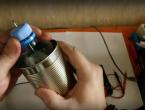
One day, on the Internet, I came across a fairly simple converter circuit for powering LEDs from one AA battery. After assembly, I was upset because the circuit turned out to be inoperative. In half an hour, the circuit was brought into working condition, the ratings of the radio components were changed, and unnecessary parts were removed, and the result was a fairly high-quality converter that is capable of powering LEDs with a power of up to 1 Watt.
The circuit itself consists of 4 parts and a throttle. Fortunately, a ready-made SMD choke was found (soldered from the radiotelephone board), but making it is also not a problem. The choke can be made on a ring from fluorescent lighting lamps (available on all energy saving boards); it contains 15 turns of wire 0.15 - 0.2 mm.

Unfortunately, I never found a direct conduction transistor in the SMD version and a powerful bipolar transistor of the KT818 series was used, but for compactness I highly recommend using SMD transistors. The second reverse conduction transistor, literally any one will do, for example the well-known KT315.
The basic resistor is 1 kilo-ohm, it is also advisable to use it in the SMD version.
A 1000 picofarad capacitor is not critical, you can deviate by 50% in one direction or another (it worked for me even with a 0.1 microfarad capacitor, but the LED will glow weaker).

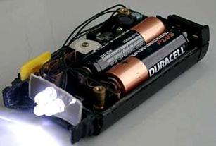
For demonstration, the circuit was assembled on a breadboard. The current consumption is 35 - 40 mA, but it increases sharply if you power the LEDs at 1 watt; the circuit does not allow more, since the maximum output current at peak is 300 mA.
The circuit starts at 0.7 volts. The maximum supply voltage is no more than 2.5 volts; if you supply more, the circuit simply will not work. The output voltage is 3.8 volts at the specified inductor parameters.
List of radioelements
| Designation | Type | Denomination | Quantity | Note | Shop | My notepad |
|---|---|---|---|---|---|---|
| Bipolar transistor | KT315A | 1 | To notepad | |||
| Bipolar transistor | KT818A | 1 | To notepad | |||
| C1 | Capacitor | 1 nF | 1 | To notepad | ||
| Resistor | 1 kOhm | 1 | To notepad | |||
| L1 | Inductor | 1 | To notepad | |||
| HL1 | Light-emitting diode | 1 |