The principle of operation and connection of the time delay timer relay. Several circuits of the relay of time and delay off the load Load off relay 220
12 schemes for the use of relays in everyday life. 2 nuances - with a delay on or off. 4 knowledge test questions. 3 best relays for ordering on aliexpress.
What is a time relay (hereinafter R.V.) with a delay
Normal relay is designed to turn on devices after receiving a signal. Time relay does not work immediately, but after the passage of a period of time specified during its manufacture or configuration. If executed with a delay, then another period is counted before switching on or off. It is also either provided in the manufacture of the device or configured (programmed).
TEST:
4 questions to test the theory- Is it possible to use a delayed relay like a regular relay?
a) No, they are completely different devices.
b) Yes, for this we set the delay to zero. (loyal)
- Are relays with on-delay and off-delay different?
a) Yes, the former work out the delay before starting the main timer, the latter only maintain the time after the shutdown command. (loyal)
- Is it possible to replace a relay with an off-delay with a relay with an on-delay?
a) No, they are different devices. (loyal)
- Can a time delay relay be replaced by two conventional time relays?
a) Yes, if they are connected correctly. (loyal).
Important to know - relay with on and off delay 2 different devices
Normal time relay turns on the device mounted after them for a period of time set during configuration. Latency devices don't work that way.
OFF-delay - 1 Reverse Operated Relay
- The relay is signaled to turn off the device.
- The countdown of the delay time begins, after the period has expired the device turns off.
If such relay mounted in front of a conventional lamp, it will not go out immediately after the switch has tripped, but after the delay time has passed.
On-delay - 2 devices in one
- On relay a signal is given, it turns on its mechanism or electronic circuit.
- The delay time is immediately counted.
- After the time has been counted, the relay turns on the connected device for the specified time.
In fact, these are two relay time connected in series.
12 ways to use a relay at home
RV connection diagram for 2 switches with a delay off 220v
OFF-delay relay it is possible to apply in order not to forget to turn off the light in the pantry or on the landing. To do this, we connect the lamp through it.

In order for the circuit to work correctly, non-latching switches must be used instead of conventional switches. Regular buttons will work too.
The scheme works as follows.
- Entering the room, you close the switch, turning on the lighting.
- The switch is not fixed in the closed position, then, releasing the switch key, you immediately interrupt the power supply.
- The lighting does not turn off, the lamps are connected via OFF-delay relay.
- The lighting will turn off only after the set time has elapsed.
- For protection, an automatic switch is installed in front of the relay, it will de-energize the device if the current rises above the set value during a short circuit (according to PUE paragraph 7 3.1.14-19).
This scheme is convenient for long corridors. Lighting can be switched on from both sides of the room. If this possibility is not needed, then the switch can be left alone.
Option 2 - delay circuit for turning on an incandescent lamp 220v on a self-assembled relay
This scheme is suitable for those , who likes to make and is familiar with radio electronics. In it, instead of a ready-made device, designed to be powered by networks 220 volts, we use a 12 relay as it's safer. We make relay from standard electromagnetic with one contact group. Scheme alterations and appearance of the device are shown in the figure below.
The above scheme is not designed to work with a powerful load due to the limited capabilities of the contact group. If such a need arises, then an intermediate relay must be introduced. No brand difference, domestic applicable RPL, RPU-2M, RP, REP or imported (today there are more of them on the market and their price is lower, the three best relays with aliexpress we present below).

Look at the picture: a standard intermediate relay. To fit it into our circuit, we connect the contacts "N" and "A" not to the points "L" and "N", but to the points "30" and "87" in the previous diagram.
RV with turn-on delay 220v 2 more circuits for lighting control
Option 2 of the lighting control device is assembled on multifunctional digital relays.

At digital relays much more possibilities. The delay can be set not for 10 15 minutes, but for a duration of more than a day. It is possible to set the time when the light will turn on. Option 1 is suitable for controlling street lighting in a personal plot. We configure the relay to turn on at 17 o'clock and work out the delay, 13 o'clock. Street lamps will burn all night, and go out at dawn.
The device is also connected to work with two managed networks, as in the second diagram. The two channels are configured completely independently.
RV 220v on an element from Schneider or another, energy savings up to 10% for an air conditioner,
Often the air conditioner is turned on with the window open, so they run idly and waste electricity. The way out of the situation is to install the sensor on the frame sash and connect it to the power line. But this approach is also not very correct.
If you open the window for a short period of time (let the cat in), the air conditioner will turn off and then turn on again. The current consumption in the start-stop mode increases, such work also does not increase the durability of the device.
We avoid problems by installing the "sensor-switch of the air conditioner" in the circuit OFF-delay relay. The diagram is shown below.

The circuit does not even provide for a special relay with a delay; its functions are performed by an ordinary intermediate relay. It works as follows.
- When the window is opened, the contacts are closed, voltage is applied to the relay.
- The current required for operation is not immediately supplied to the corresponding terminals, but is spent to charge the capacitors. For decoupling in scheme diodes are on.
- After the capacitors are charged, the current rises to the value necessary for the relay to operate. The relay turns off the air conditioner.
- If the window is already closed, then after the capacitors are discharged (due to the minimum current flow in the opposite direction through the diode), the relay again supplies voltage to the air conditioner.
R. turn-on delay 220v 2 repair option for the refrigerator.
If it is difficult to find a regular temperature sensor, the option is to install any suitable one. And in order for the compressor not to turn on and off, we mount the same circuit as for the air conditioner.
Modernization of the control of 4 power windows
Normally, the windows in the car do not work when the ignition is off. A case is possible - having stopped for a few seconds, we cannot open the window to pay the refueling operator. To eliminate the situation, we modernize the electrical equipment control circuit by setting switch-off delay relay.
Option homemade time relay with a delay of 24 volts
The previous circuit provided power from a 12 volt unit. We offer another option, powered by 24 V. It is suitable for trucks, in their network such voltage.

The device is assembled on domestic elements, canopy installation. With the help of a variable resistor (it is at the very bottom of the circuit), the turn-off delay time is adjusted.
3rd power window control scheme on imported parts
If there are problems with the acquisition of domestic radio elements, we assemble relays with a delay on imported ones. Parts are soldered from the boards of a failed computer. Below is a diagram.

The device works in the same way. By changing the capacitance of the capacitor C1 or resistor R2, we adjust the delay time.
DIY time relay
R. turn off delay 220v fan for 1 hour with your own hands
Another use case delayed relay- fan or extractor control in the shower or lavatory. Here is a diagram for assembling it yourself.

It works in two modes selectable with a switch on the relay. The signal for the relay to operate is the supply of voltage to the lighting of the room.
For shower:
- Lights are turned on in the room.
- You are using the bathroom.
- When you left, you turned off the light.
- The delay time starts (until steam accumulates).
- After a delay, the fan turns on for the time necessary to remove the steam.
For restroom:
- After the light is on, the countdown begins.
- After half a minute or more (depending on the settings), the hood will turn on.
- The fan runs for the programmed time.
R. temp. with delayed switch-off options 2 and 3, 220V for exhaust
The proposed scheme can be assembled on imported relays, two options are shown below.

The algorithm of these schemes is as follows.
- Simultaneously with the inclusion of lighting, the hood is turned on.
- After the lighting is turned off, the countdown begins.
- When the delay has passed, the fan is de-energized.
Devices are configured for the operating time after turning off the light is 15 minutes. To change the delay, it is enough to turn the knob on their panel with a Phillips screwdriver or any similar tool.
Scheme for extracting RV with a delay off 220v on a domestic component or option 2 on a device from abb
Instead of with special relays for fan, use multi-functional. The figure below shows domestic models, but it is easy to find and select imported ones.

The option is to choose ABB products.

Devices are connected to the fan power circuit, and then the knobs adjust the operating time and delays.
Domestic relays are two-channel, the second channel can be used to control lighting. To do this, you need to set them so that the light goes out after a time sufficient to use the room. Energy savings are achieved if there are forgetful people in the house.
Homemade R. for delaying the activation of a car alarm
Another option for using the delay is to include it in the car alarm circuit. Variants of this security system block the doors immediately after you close them, this is not very convenient, slamming the car with the keys and the alarm control key fob remains on the street. If you mount the relay with a delay of one or two minutes, the driver will have time to correct the error. Here is a variant of the diagram.

The device is assembled on domestic radioelements by a canopy and is included in the power supply circuit of the security system. By changing the capacitance of the capacitor, you can adjust the delay time.
RV with turn-off delay 220v from 3 best devices from aliexpress
Buying a relay on the aliexpress portal saves money. We list the top three devices on this service.
First, second and third number in our relay rating
Answers to frequently asked questions
At the end of the article, we will answer some of the most frequently asked questions.
Question. Which option is preferable for a 12 V relay and an intermediate one for 220 or immediately designed for high voltage?
Answer. First option more secure when setting up, the second is easier to install.
Question. Which relay is preferable mechanical or electronic?
Answer. Mechanical cheaper, electronic reliability and functionality they are surpassed.
Question. Are imported devices more reliable?
Answer. Russian standards are tougher than foreign ones, so it is preferable to choose domestic devices.
3 common mistakes when choosing R.V.
- Select a relay whose maximum or minimum adjustable operating period is close to the required operating period. It is necessary that the time that the device will most often work out is in the middle third.
- The relay is not designed for the connected load. Before choosing, determine the maximum current of the controlled relay devices and study its characteristics.
- The device intended for premises is mounted in the open air. The relay for outdoor installation must have a protection class of at least IP 68.
We hope this article was not only informative, but also practically useful. It’s great if she helped make the home more comfortable and cozy.
With the help of electronic relays, you can save money well, for example, take the light in the corridor, pantry or entrance. By pressing the button, we turn on the light and after a certain time it automatically turns off. This time should be enough to search for an object in the hallway, closet or getting into the apartment. In addition, the lighting unnecessarily does not burn if you forgot to turn it off. This device is not only useful, but also very convenient. In this article, we will tell you how to make a time relay with your own hands, providing all the necessary diagrams and instructions.
The simplest option
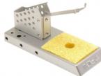
An example of a constructor for homemade assembly of a shutdown delay timer:
If desired, it is possible to independently assemble the time relay according to the following scheme:
The timing element is C1, in the standard kit of the kit it has the following characteristics: 1000 uF / 16 V, the delay time in this case is approximately 10 minutes. Time adjustment is carried out by variable R1. Power board 12 volts. The load is controlled through the relay contacts. You can not make a board, but assemble it on a breadboard or by surface mounting.

In order to make a time relay, we need the following parts:
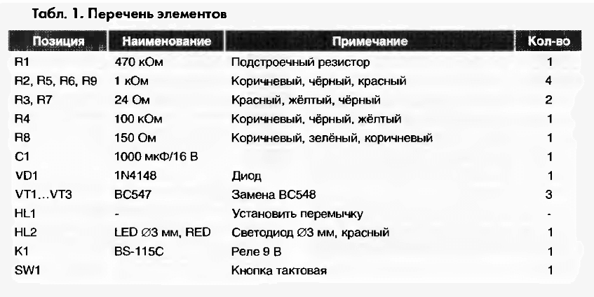
A properly assembled device does not need to be configured and is ready to go. This self-made time delay relay was described in the journal "Radiodelo" 2005.07.
Homemade based on the NE 555 timer
Another do-it-yourself electronic timer circuit is also easy and affordable to repeat. The heart of this circuit is the NE 555 integrated timer chip. This device is designed to both turn off and turn on devices, below is a diagram of the device:

NE555 is a specialized microcircuit used in building all kinds of electronic devices, timers, signal generators, etc. It is quite common, so it can be found in any radio shop. This microcircuit controls the load through an electromechanical relay, which can be used both to turn on and off the payload.
The timer is controlled by two buttons: "start" and "stop". To start the countdown, you must press the "start" button. Disabling and returning the device to its original state is carried out by the "stop" button. The node that sets the time interval is a chain of a variable resistor R1 and an electrolytic capacitor C1. The value of the turn-on delay depends on their rating.

Given the values of the elements R1 and C1, the time range can be from 2 seconds to 3 minutes. An LED connected in parallel with the relay coil is used as an indicator of the state of the design's operability. As in the previous circuit, its operation requires an additional external 12 volt power supply.
In order for the relay to turn on itself immediately when the power is applied to the board, it is necessary to slightly change the circuit: connect pin 4 of the microcircuit to the positive wire, turn off pin 7, and connect pins 2 and 6 together. You can learn more clearly about this scheme from the video, which describes in detail the process of assembling and working with the device:
Relay on one transistor
The easiest option is to use a time relay circuit with just one transistor, KT 973 A, its imported counterpart BD 876. This solution is also based on charging the capacitor to the supply voltage, through a potentiometer (variable resistor). The highlight of the circuit is the forced switching and discharge of the capacitance through the resistor R2 and the return of the initial initial position with the toggle switch S1.
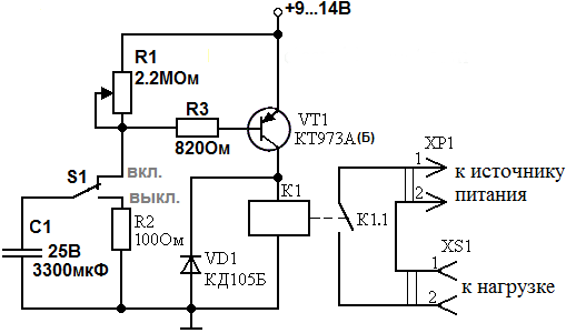
When power is applied to the device, the capacitance C1 begins to charge through the resistor R1 and through R3, thereby opening the transistor VT1. When the capacitance is charged to the VT1 shutdown state, the relay is de-energized, thereby turning off or turning on the load, depending on the purpose of the circuit and the type of relay used.
The elements you have chosen may have a slight variation in denominations, this will not affect the operation of the circuit. The delay may vary slightly and depend on the ambient temperature, as well as on the magnitude of the mains voltage. The photo below shows an example of a finished homemade product:

Now you know how to make a time relay with your own hands. We hope the instructions provided were useful to you and you were able to assemble this homemade product at home!
Today, there are many devices designed to facilitate the life of a modern person. So, time relays also moved from the industrial sphere to the household one, allowing you to automate the work of modern electrical appliances and systems. What types of time relays the modern market offers, how to choose a time regulator and assemble the device with your own hands - read below.
What is a time delay relay
Time delay relays are special devices, the main purpose of which is to ensure the sequential operation of circuit elements for a certain time after the power is turned on or off. The delays created by the relay can be both minute and hourly, as well as daily, weekly in duration. At the same time, with the help of one signal, the relay is able to simultaneously control the operation of several circuits.
According to the principle of operation, time delay relays are divided into devices:
- With electromagnetic deceleration;
- With pneumatic deceleration mechanism;
- With clock or anchor mechanism;
- motor type.
Separately allocate electronic time relays. The time delay in such devices is implemented through analog and digital technical solutions. Often these solutions are represented by digital timers.

Electronic relays are widely used due to the widest range of time delay adjustment.
Thus, an electronic relay is capable of controlling the operation of circuit elements with a time delay from a fraction of a second to several thousand hours. In addition, the advantages of electronic relays include their small size, economical power consumption and versatility. There are also time relays running on microprocessors. Such models are considered the most effective.
Time delay relay classification
For convenience, the time relay is classified according to the type of execution. This classification allows you to divide devices into relays for industrial use and household controllers.
So, all time delay relays are divided into:
- Monoblock;
- Embedded;
- Modular.
The easiest way to install monoblock and modular devices. Monobloc relays are self-contained devices for external installation. Such devices are equipped with built-in batteries, have terminals for connecting the load. Modular relays are a type of monoblock, and are used for installation in electrical panels.

The most common in the industrial and economic sphere are built-in relays.
They are actively used in modern household electrical installations (for example, washing machines), smart home systems. In addition, such devices are used in the automation of greenhouses.
Scope of application of time relay with off-delay
The scope of time relays is extremely wide and depends on the type of device. So, all time relays are divided into devices with a turn-on delay after power is applied and devices with a turn-off time delay after the load is turned off. The most common in the household and utilities are relays with a time delay off.
Most often, devices that create a turn-off delay are used to:
- Automation of street and indoor lighting;
- control over irrigation systems;
- Automation of ventilation systems;
- Control over the operation of household pumps, gas boilers, electric water heaters.
Thus, time relays allow the use of various electrical equipment only according to its actual need, eliminating the possibility of its inappropriate use. This not only saves energy consumption, but also extends the life of electrical appliances.
Relays with a turn-on delay are used to control the operation of industrial and household automation.
So, for example, devices can be used to automatically restore the operation of household appliances, lighting fixtures, ventilation, and heating systems after the resumption of power supply. When properly connected and well configured, delayed turn-on relays can activate the floor heating system when you arrive, turn on water heaters and turn on household appliances (for example, a coffee machine) after you wake up.
The main criterion for choosing a time relay for single-phase networks (220 V) is the delay range. This parameter is determined by the purpose of the trip device. So, for example, for a relay connected to a fan in a bathroom, a turn-off delay in the range from 1 second to 1 hour will be sufficient.
Time relays with turn-on delay usually have a smaller range.
This is related to the scope of their use. Often, after the restoration of power supply, the inclusion of industrial, household and household automation should be carried out immediately. So, the delay for turning on household electrical equipment should be no more than 2 minutes.

In addition, when choosing a time relay, you must consider:
- Switched current type. Relays can switch both alternating and direct current. AC type relay should be selected for AC switching, DC type for DC switching. There are also universal devices labeled AC / DC.
- Maximum switching current. Relays capable of switching loads in the range from 10 to 16 A are suitable for domestic use.
- Degree of protection of the device. For indoor installation, relays with an IP20 index are suitable. For outdoor installation, this figure must be doubled, or the relay must be installed in a protective housing.
- Relay connection options. Separate models of time relays can be simultaneously connected to two elements that control the load (for example, to two switches). So the operation of the relay can be controlled from two points located at different ends of the room.
Do not forget about the overall dimensions and method of mounting the device. This will allow you to quickly fit the device into the project. So, electronic installations have the smallest dimensions. In addition, the timing relay may or may not require mounting a DIN rail.
12 volt relay turn-on delay circuit
You can assemble a simple relay with your own hands. The easiest electronic time relay circuit to implement is assembled on the basis of the ne555 integrated timer. The relay is controlled by pressing external keys. 12V will be enough to operate the device. The relay can be powered through the power cable to the mains. A 12 volt battery can also temporarily support the operation of the relay.
The circuit of a simple time relay based on the NE 555 timer also has the following features:
- The time interval setting node is a circuit of an AC resistor and an electrolytic capacitor. The delay interval for turning on the time relay depends on their rating.
- With a resistor value of 500 kΩ and a capacitor of 220 µF, the delay range can be from 2 seconds to 3 minutes.
- An LED connected in parallel to the coil can act as an indicator of the relay's operability.
This device can be used both to turn off and turn on electrical equipment with a time delay. To start the time countdown, you must press the “start” button, which starts the timer. The “stop” button is responsible for turning off the power and returning the device controlled by the relay to its original state.
The time delay relay is designed to adjust the sequence of operation of certain elements of the electrical circuit. Basically, such devices are used in devices that require automatic execution of a certain action after a set period of time.
General information about the device
A relay is a device that works like a battery. The duration of the working mechanism can be daily, weekly, hourly. Install these devices where you need to control circuits that have low power. In this case, there is complete isolation between the control and controlled conductors. The relay is designed to control several circuits at the same time, using a single signal.
Initially, relays were used in long-distance telephone circuits. They acted as an amplifier: they duplicated the signal from one circuit to another and transmitted it in a chain reaction. The relay worked in the first computers, carried out simple commands in logical circuits.
What is the relay used for? electromagnetic field? It is a shock absorber that slows down or completely de-energizes the movement when the coil suddenly enters the voltage environment. It is this property that makes it possible for the relay to delay time: the time of connecting the armature to the voltage coil slows down.
Several options for such devices
Using a time relay makes it possible to save on electricity consumption, as the light will turn on and off automatically after a set period of time.
How the time delay relay works
 Due to the fact that the electric current creates a magnetic field with the help of conductors, the current state of the relay reacts with inductors to all changes. Locations of the magnetic field will depend on the shape of the conductor. If it is made at a right angle, then the field will be located in the same way, if in the form of a coil, then the magnetic field will be located along its entire length. The strength of the magnetic field directly depends on the voltage.
Relays have become popular because they have proven to be effective in use. They can control large and small voltages. The relay coil is capable of passing fractions of a watt through itself, while the contacts carry hundreds of watts of load energy.
The operating principle of the relay is binary amplifier on and off. As practice shows, one relay coil can actuate several contacts of one device. These can be contacts of any combination. The device works with contacts of any kind: mercury, metal, magnetic reeds.
What is a delay relay?
If the device is a simple two-channel electromagnetic relay, then it includes:

The armature is hinged to the yoke and mechanically connected to one or more sets of contacts. The anchor itself is held by a spring. It is installed in such a way that during the absence of current, a magnetic circuit is formed air gap. In this mode of the device, one of the contacts is in the closed position, the other is in the open position. Some types of devices have more contacts, it all depends on the functions provided.
When an electric current arrives, a magnetic field is generated, which makes it possible to activate the armature with the subsequent movement of the movable contact. This allows you to make breaks or connections with fixed contacts. When the contacts are open, the contacts are connected and closed; when the contacts are turned off, the actions are opposite. When the current is off, the armature takes its original position and returns under the action of a force that is several times less than the magnetic one, so its position is normally relaxed. Most often, this force is provided by a spring, gravity is used only in industrial installations.
When current is applied to the coil, the diode passes through it and dissipates energy from the decaying magnetic field during deactivation. If this process does not start, then the components of the circuit will receive an energy surge, which will lead to their failure.
DIY delay relay
To create a relay with a turn-off delay of 220 V, you do not need special electromechanical knowledge, it will be enough to have basic knowledge in physics and electromechanics. Exists definite guidance, which will help you assemble the relay yourself.

For a time relay, it is considered optimal using transistor circuits. Such relays are great for controlling the operation of the wipers on the car, turning the lights on and off on the street, and the operation of the washing machine. The 220V relay turn-on delay is an excellent option that combines domestic conveniences and excellent savings.
To control the sequence of operation of electrical appliances, a time relay with a turn-off delay of 220 V is used. After turning on the electrical device, the load is disconnected after a specified time. Thus, the sequence of operation of the elements of the electrical circuit is regulated and electrical appliances and technological processes are controlled.
Relay types
All relays are divided into devices with galvanic isolation and without galvanic isolation. Galvanic isolation refers to the electrical isolation of circuits with respect to other circuits nearby. There is complete isolation between the control circuit and the controlled circuits.
In practice, the following devices are used:


Electronic timers are highly accurate, but their delay interval is much shorter than that of electromagnetic ones, and they require programming. Electromagnetic devices are less expensive and easier to set up. They do not require maintenance, but their service life is limited.
 Time relay can be divided into built into appliances and separately purchased. In multicookers, washing machines and dishwashers, timers are programmed, their operation cannot be influenced. You can independently use separate timers that control lighting, heating, opening doors. The most common are digital timers, which are based on a quartz resonator with a stable frequency.
Replacing human labor in managing various mechanical devices, increasing the productivity of devices without human intervention, increasing production safety - these tasks can be performed by time relays.
Installation characteristics
According to the characteristics, the possibility of using the devices in certain operating conditions is determined. The properties of time delay settings have four directions:

Each timer is characterized by certain parameters. The algorithm of work is important, namely the sequence of switching on and off.
The most commonly used algorithms are:
- Turn-on delay - after power is supplied to the timer, the output pulse is formed after the set time has elapsed.
- The pulse is generated when the timer is turned on - the signal appears at the moment the timer is turned on and disappears after the set time has elapsed.
- After turning on the power supply of the timer, the output signal appears at the moment the control signal is removed and disappears after the set time.
- Turn-off delay after power off - the output signal appears at the time of power-up of the timer and disappears after a set time after power off.
- Cyclic mode - after turning on the power supply of the timer, the pulse time alternates with the pause time and so on until the power supply is turned off.

In order to connect the timer, you need to know in which network it will be mounted - single-phase or three-phase. It is important to consider what this timer will switch, what load needs to be turned off or on. Using this data, you can choose a device with the necessary characteristics.