Where can I find a stabilizer for 7805. Voltage stabilizer. Smooth output stabilizer
I converted the speaker amplifier to a penny D-class module on the PAM8403. The speakers began to play louder, a type of bass appeared. Satisfied. But there was one problem - if you supply power to the speakers from the usual (pulse) charging at 5V, there were large distortions in the power supply. At a low volume it was still possible to listen, at a high volume it was impossible. I decided to solder the power supply with linear stabilization.
The scheme of such a PSU is simple:
The first impulse is to buy all the details in the local "Electronics" and quickly solder the power supply circuit on the breadboard. I calculated only the price of stabilizer parts - it turned out about 700 rubles. The toad choked. Let's look at ready-made options on Ali and ebee. Everything here is chocolate. There are penny designers (to solder on the printed circuit board yourself), there are ready-made modules for 110 rubles. I ended up buying it on eBay, it was cheaper there. It's been three weeks. The stabilizer dangled on the radiator - screwed it tight. 
The rest of the details are a transformer, a fuse, a case, a power button, legs for the case, a usb connector in Electronics. It took 500 rubles for everything.
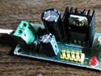
Characteristics of the module and stabilizer LM7805:
1. Board size. 57mm*23mm
2. Input voltage input voltage polarity, AC and DC can, range. 7.5-20V
3. The output voltage 5V
4. The maximum output current. 1.2A
5. Provided fixed bolt hole, convenient installation
As you can see, voltage from 7.5V to 20V can be applied to the module. The output is 5V.
The stabilizer inside is quite complicated: 
The transformer bought such a TP112 (7.2 W) 2 * 12V xx - 
I took the power button for 220 V - quite large. 
Button with fixation and backlight. How to connect the backlight when pressed - I did not understand (can you tell me, who knows?). I did it without backlight. 
Assembled a stand for testing: 
Speakers play without distortion at maximum volume. Nothing in the PSU gets very hot. Goal achieved: 
I tried to charge the phone - current 0.5A 
With a 1 A resistor, everything is quite sad: 
Conclusion - this power supply cannot be used as a charger. Apparently the transformer needs to be put more powerful.
Putting it all together: 


I made a hole on top in order to see the LED - an indicator on the module to indicate operation. On the reverse side, the hole was sealed with a transparent film.
Thank you for your attention.
I plan to buy +14 Add to favorites Liked the review +23 +38It is known that the brightness of the LED is very dependent on the current flowing through it. At the same time, the current of the LED is very steeply dependent on the supply voltage. This results in noticeable brightness ripples even with slight power instability.
But ripple is not terrible, what is much worse is that the slightest increase in the supply voltage can lead to such a strong increase in current through the LEDs that they simply burn out.
To prevent this, LEDs (especially powerful ones) are usually powered through special circuits - drivers, which are essentially current stabilizers. This article will consider circuits of simple current stabilizers for LEDs (on transistors or common microcircuits).
There are also very similar LEDs - SMD 5730 (without a unit in the name). They have a power of only 0.5 W and a maximum current of 0.18 A. So do not confuse.
Since when the LEDs are connected in series, the total voltage will be equal to the sum of the voltages on each of the LEDs, the minimum supply voltage of the circuit should be: Upit \u003d 2.5 + 12 + (3.3 x 10) \u003d 47.5 Volts.
You can calculate the resistance and power of the resistor for other current values \u200b\u200busing a simple Regulator Design program (download). 
Obviously, the higher the output voltage of the stabilizer, the more heat will be generated on the current-setting resistor and, therefore, the worse the efficiency. Therefore, for our purposes, the LM7805 is better suited than the LM7812.
LM317
Equally effective is a linear current regulator for LEDs on the LM317. Typical switching circuit: 
The simplest LM317 switching circuit for LEDs, which allows you to assemble a powerful lamp, consists of a rectifier with a capacitive filter, a current stabilizer and 93 LEDs SMD 5630. MXL8-PW35-0000 (3500K, 31 Lm, 100 mA, 3.1 V, 400 mW, 5.3x3 mm) are used here. 
If such a large garland of LEDs is not needed, then a ballast resistor or capacitor will have to be added to the driver on the LM317 to power the LEDs (to extinguish the excess voltage). How to do this, we considered in great detail in.
The disadvantage of such a current driver circuit for LEDs is that when the voltage in the network rises above 235 volts, the LM317 will be outside the calculated operating mode, and when it drops to ~ 208 volts and below, the microcircuit completely ceases to stabilize and the depth of the ripples will depend entirely and completely from tank C1.
Therefore, it is necessary to use such a lamp where the voltage is more or less stable. And the capacitance of this capacitor is not worth saving. The diode bridge can be taken ready-made (for example, a miniature MB6S) or assembled from suitable diodes (U arr at least 400 V, forward current >= 100 mA). Perfect for the ones mentioned above. 1N4007.
As you can see, the circuit is simple and does not contain any expensive components. Here are the current prices (and they are likely to drop further):
| Name | characteristics | price |
|---|---|---|
| SMD 5630 | LED, 3.3V, 0.15A, 0.5W | 240 rub. / 1000pcs |
| LM317 | 1.25-37V, >1.5A | 112 rub. / 10 pieces. |
| MB6S | 600V, 0.5A | 67 rub. / 20pcs |
| 120µF, 400V | 18x30mm | 560 rub. / 10 pieces. |
Thus, spending a total of 1000 rubles, you can collect a dozen 30-watt (!!!) non-flickering (!!!) light bulbs. And since the LEDs do not operate at full capacity, and the only electrolyte does not overheat, these lamps will be almost eternal.
Instead of a conclusion
The disadvantages of the schemes given in the article include low efficiency due to the useless waste of power on the regulatory elements. However, this is characteristic of all linear current stabilizers.
Low efficiency is unacceptable for devices powered by autonomous current sources (lamps, flashlights, etc.). A significant increase in efficiency (90% or more) can be achieved by using.

Nowadays it is hard to find any electronic device that does not use a stabilized power supply. Basically as a power source, for the vast majority of various electronic devices designed to operate from 5 volts, the best option would be to use a three-pin integrated 78L05.
Description of stabilizer 78L05
This stabilizer is inexpensive and easy to use, which makes it easier to design electronic circuits with a significant number of printed circuit boards, to which an unstabilized DC voltage is supplied, and each board has its own stabilizer mounted separately.
Chip - stabilizer 78L05 (7805) has thermal protection, as well as a built-in system that protects the stabilizer from overcurrent. However, for more reliable operation, it is desirable to use a diode to protect the stabilizer from a short circuit in the input circuit.
Technical parameters and pinout of the stabilizer 78L05:
- Input voltage: 30 volts.
- Output voltage: 5.0 volts.
- Output current (maximum): 100 mA.
- Current consumption (stabilizer): 5.5 mA.
- Permissible input-output voltage difference: 1.7 volts.
- Operating temperature: -40 to +125 °C.


Multifunctional device for testing transistors, diodes, thyristors...
Stabilizer analogues 78L05 (7805)
There are two types of this microcircuit: powerful 7805 (load current up to 1A) and low-power 78L05 (load current up to 0.1A). The foreign analogue of 7805 is ka7805. Domestic analogues are for 78L05 - KR1157EN5, and for 7805 - 142EN5
Wiring diagram 78L05
A typical 78L05 stabilizer switching circuit (according to the datasheet) is easy and does not require a large number of additional radio elements.

C1 at the input is necessary to eliminate RF interference when the input voltage is applied. Capacitor C2 at the output of the stabilizer, as in any other power source, ensures the stability of the power supply with a sharp change in the load current, and also reduces the degree of ripple.
When developing a power supply, it must be borne in mind that for stable operation of the 78L05 stabilizer, the input voltage must be at least 7 and not more than 20 volts.
Below are a few examples of how the 78L05 Integral Regulator is used.
Laboratory power supply on 78L05
This circuit is distinguished by its originality, due to the non-standard use of the microcircuit, the reference voltage source of which is the 78L05 stabilizer. Since the maximum allowable input voltage for 78L05 is 20 volts, a parametric stabilizer on the zener diode VD1 and resistor R1 is added to the circuit to prevent the 78L05 from failing.

The TDA2030 chip is connected as a non-inverting amplifier. With this connection, the gain is 1 + R4 / R3 (in this case 6). Thus, the voltage at the output of the power supply, when the resistance of the resistor R2 changes, will change from 0 to 30 volts (5 volts x 6). If you need to change the maximum output voltage, then this can be done by selecting the appropriate resistance of the resistor R3 or R4.

Adjustable Power Supply Assembly Kit...
5 volt transformerless power supply
this one is characterized by increased stability, lack of heating of the elements and consists of available radio components.

The structure of the power supply includes: a power indicator on the HL1 LED, instead of a conventional transformer, a quenching circuit on elements C1 and R2, a diode rectifier bridge VD1, capacitors to reduce ripples, a 9 volt VD2 zener diode and an integrated voltage regulator 78L05 (DA1). The need for a zener diode is due to the fact that the voltage from the output of the diode bridge is approximately 100 volts and this can disable the 78L05 stabilizer. You can use any zener diode with a stabilization voltage of 8 ... 15 volts.
Attention!Since the circuit is not galvanically isolated from the mains, care should be taken when setting up and using the power supply.
Simple regulated power supply on 78L05

The adjustable voltage range in this circuit is from 5 to 20 volts. The output voltage is changed using a variable resistor R2. The maximum load current is 1.5 amperes. The 78L05 stabilizer is best replaced with 7805 or its domestic counterpart KR142EN5A. Transistor VT1 can be replaced with. It is desirable to place a powerful transistor VT2 on a radiator with an area of at least 150 square meters. cm.

Simple and intuitive operation, fast and accurate selection of voltage and current...
Diagram of a universal charger
This charger circuit is quite simple and versatile. Charging allows you to charge all kinds of batteries: lithium, nickel, as well as small lead batteries used in uninterruptible power supplies.

It is known that when charging batteries, a stable charging current is important, which should be approximately 1/10 of the battery capacity. The constancy of the charging current is provided by the stabilizer 78L05 (7805). The charger has 4 charging current ranges: 50, 100, 150 and 200 mA, which are determined by the resistances R4 ... R7, respectively. Based on the fact that the output of the stabilizer is 5 volts, then to obtain 50 mA, a 100 ohm resistor (5V / 0.05 A = 100) is required, and so on for all ranges.
The circuit is also equipped with an indicator built on two transistors VT1, VT2 and an HL1 LED. The LED turns off when the battery is charging.

charging current: 500mA/h, 1000mA/h. charging modes at constant...
Adjustable current source
Due to the negative feedback following through the load resistance, there is a voltage Uin at input 2 (inverting) of the TDA2030 (DA2) microcircuit. Under the influence of this voltage, a current flows through the load: Ih = Uin / R2. Based on this formula, the current flowing through the load is not dependent on the resistance of this load.

Thus, by changing the voltage coming from the variable resistor R1 to input 1 DA2 from 0 to 5 V, with a constant value of the resistor R2 (10 Ohm), you can change the current flowing through the load in the range from 0 to 0.5 A.
Such a scheme can be successfully applied as a charger for charging all kinds of batteries. The charging current is constant during the entire charging process and does not depend on the level of discharge of the battery or on the inconsistency of the supply network. The limiting charge current can be changed by decreasing or increasing the resistance of the resistor R2.
(161.0 KiB, downloaded: 6,505)
Positive voltage at 5V. Produced by STMircoelectronics, the approximate price is about $ 1. It is made in a standard TO-220 package (see figure), in which many transistors are made, however, its purpose is completely different.
In the marking of the 78XX series the last two digits indicate stabilized voltage rating, for example:
- 7805 - stabilization at 5 V;
- 7812 - stabilization at 12 V;
- 7815 - stabilization at 15 V, etc.
Series 79 is designed for negative output voltage.
Is used for voltage stabilization in various low-voltage circuits. It is very convenient to use when it is necessary to ensure the accuracy of the supplied voltage, it is not necessary to fence complex stabilization circuits, and all this can be replaced with one microcircuit and a couple of capacitors.
Connection diagram L7805CV
Connection diagram L 7805 CV quite simple, for operation it is necessary, according to the datasheet, to hang capacitors at the input of 0.33 microfarads, and at the output of 0.1 microfarads. It is important during installation or design to place the capacitors as close as possible to the pins of the microcircuit. This is done to ensure the maximum level of stabilization and reduce interference.
By characteristics The L7805CV stabilizer is operable when an input DC voltage is applied in the range from 7.5 to 25 V. The output of the microcircuit will have a stable DC voltage of 5 Volts. This is the beauty of the L7805CV chip.
L7805CV Performance Check
 How to check if it works microchips? To begin with, you can simply ring the conclusions with a multimeter, if at least in one case there is a short circuit, then this clearly indicates a malfunction of the element. If you have a power source of 7 V and higher, you can assemble the circuit according to the datasheet above and apply power to the input, we fix a voltage of 5 V at the output with a multimeter, respectively, the element is absolutely operable. The third method is more time consuming if you do not have a power source. However, in this case, you will also receive a 5 V power supply in parallel. You need to assemble a circuit with a rectifier bridge according to the figure below.
Needed to check a step-down transformer with a transformation ratio of 18 - 20 and a rectifier bridge, a further body kit is a standard two capacitors per stabilizer and that's it, a 5 V power supply is ready. The values of the capacitors here are overestimated in relation to the L7805 switching circuit in the datasheet, this is due to the fact that it is better to smooth out the voltage ripple after the rectifier bridge. For safer operation, it is desirable to add an indication to visualize the inclusion of the device. Then the diagram will look like this:
If there are a lot of capacitors or any other capacitive load on the load, you can protect the regulator with a flyback diode to prevent the element from burning out when the capacitors are discharged.
The big advantage of the microcircuit is light enough construction and ease of use, in case you need a power supply of one value. Voltage-sensitive circuits must be equipped with such stabilizers in order to protect elements sensitive to voltage surges.
Characteristics of the stabilizer L7805CV, its analogues
Main settings stabilizer L7805CV:
- Input voltage - from 7 to 25 V;
- Dissipated power - 15 W;
- Output voltage - 4.75 ... 5.25 V;
- Output current - up to 1.5 A.
 Chip characteristic shown in the table below, these values are valid subject to certain conditions. Namely, the temperature of the microcircuit is in the range from 0 to 125 degrees Celsius, the input voltage is 10 V, the output current is 500 mA (unless otherwise specified in the conditions, the Test conditions column), and the standard kit with capacitors is 0.33 uF at the input and 0 at the output .1 uF.
It can be seen from the table that the regulator behaves perfectly when powered at the input from 7 to 20 V and the output will be stable from 4.75 to 5.25 V. On the other hand, supplying higher values \u200b\u200bleads to a more significant spread in the output values. , therefore, above 25 V is not recommended, and lowering the input to less than 7 V, in general, will lead to a lack of voltage at the output of the stabilizer.
More than 5 W, it is necessary to install a radiator on the microcircuit in order to avoid overheating of the stabilizer, the design allows this to be done without any questions. For more accurate (precision) technology, of course, such a stabilizer is not suitable, because. has a significant variation in the rated voltage when the input voltage changes.
Since the stabilizer is linear, it is pointless to use it in powerful circuits; stabilization based on pulse-width modeling is required, but to power small devices, as phones, children's toys, radio tape recorders and other gadgets, the L7805 is quite suitable. The analogue is domestic - KR142EN5A or in the common people "KRENK". In terms of cost, the analogue is also in the same category.
Stabilizers these are devices that are part of the power supply and allow you to keep a stable voltage at the output of the power supply. Voltage stabilizers are designed for some fixed output voltage (for example, 5V, 9V, 12V), and there are adjustable voltage stabilizers that have the ability to set the required voltage within the limits they allow.
All stabilizers are necessarily designed for some maximum current that they can provide. Exceeding this current threatens the failure of the stabilizer. Modern stabilizers are necessarily equipped with current protection, which ensures that the stabilizer is turned off when the maximum current in the load is exceeded and overheating protection. Along with positive voltage stabilizers, there are negative voltage stabilizers. They are mainly used in bipolar power supplies.
7805 - stabilizer
7805 - stabilizer
This stabilizer has a low-power counterpart.
7805 pinout
At the stabilizer 7805 pinout
In discussions of electrical circuits, the terms "voltage regulator" and "current regulator" are often used. But what is the difference between them? How do these stabilizers work? In which circuit do you need an expensive voltage regulator, and where is a simple regulator enough? You will find answers to these questions in this article.
Consider a voltage regulator using the LM7805 device as an example. Its characteristics indicate: 5V 1.5A. This means it stabilizes the voltage and it is up to 5V. 1.5A is the maximum current that the stabilizer can conduct. Peak current. That is, it can give away 3 milliamps, and 0.5 amperes, and 1 ampere. As much as the current required by the load. But no more than one and a half. This is the main difference between a voltage stabilizer and a current stabilizer.
Types of voltage stabilizers
There are only 2 main types of voltage stabilizers:
- linear
- impulse
Linear Voltage Regulators
For example, microchips BANK or, LM1117, LM350.
By the way, KREN is not an abbreviation, as many people think. This is an abbreviation. The Soviet stabilizer chip, similar to the LM7805, had the designation KR142EN5A. Well, there is also KR1157EN12V, KR1157EN502, KR1157EN24A and a bunch of others. For brevity, the entire family of microcircuits began to be called "KREN". KR142EN5A then turns into KREN142.
Soviet stabilizer KR142EN5A. Analog LM7805.

Stabilizer LM7805
The most common type. Their disadvantage is that they cannot operate at a voltage lower than the declared output voltage. If it stabilizes the voltage at 5 volts, then it needs to be applied to the input at least one and a half volts more. If you apply less than 6.5 V, then the output voltage will “sag”, and we will no longer get 5 V. Another disadvantage of linear stabilizers is strong heating under load. Actually, this is the principle of their work - everything that is higher than the stabilized voltage simply turns into heat. If we apply 12 V to the input, then 7 will be spent on heating the case, and 5 will go to the consumer. At the same time, the case will heat up so much that without a radiator, the microcircuit will simply burn out. Another serious drawback follows from all this - a linear stabilizer should not be used in battery-powered devices. The energy of the batteries will be spent on heating the stabilizer. All these shortcomings are deprived of impulse stabilizers.
Switching voltage stabilizers
Switching stabilizers- devoid of the disadvantages of linear, but also more expensive. This is no longer just a microcircuit with three pins. They look like a board with parts.

One of the options for the execution of a pulse stabilizer.
Switching stabilizers There are three types: lowering, increasing and omnivorous. The most interesting are omnivores. Regardless of the input voltage, the output will be exactly what we need. The omnivorous impulsnik does not care that the voltage at the input is lower or higher than the desired one. He automatically switches to the mode of increasing or decreasing the voltage and keeps the specified output. If the characteristics state that the stabilizer can be input from 1 to 15 volts and the output will be stable 5, then it will be so. In addition, heating switching regulators is so small that in most cases it can be neglected. If your circuit will be powered by batteries or placed in a closed case, where strong heating of the linear stabilizer is unacceptable - put a pulse. I use penny adjustable switching voltage regulators that I order from Aliexpress. You can buy.
Fine. And what about the current stabilizer?
I won't discover America if I say that current stabilizer stabilizes current.
Current stabilizers are sometimes also called LED driver. Outwardly, they look like switching voltage stabilizers. Although the stabilizer itself is a small microcircuit, everything else is needed to ensure the correct mode of operation. But usually the whole circuit is called a driver at once.

This is what a voltage stabilizer looks like. The circuit circled in red is the same circuit that is the stabilizer. Everything else on the board is wiring.
So. The driver sets the current. Stable! If it is written that the output will have a current of 350mA, then it will be exactly 350mA. But the output voltage can vary depending on the voltage required by the consumer. Let's not get into the wilds of the theory about that. how it all works. Just remember that you do not regulate the voltage, the driver will do everything for you based on the consumer.
So why is all this necessary?
Now you know how a voltage stabilizer differs from a current stabilizer and you can navigate their diversity. Perhaps you never understood why these things are needed.
Example: you want to power 3 LEDs from the car's electrical system. As you can learn from, it is important for the LED to control the current strength. We use the most common option for connecting LEDs: 3 LEDs and a resistor are connected in series. Supply voltage - 12 volts.
With a resistor, we limit the current to the LEDs so that they do not burn out. Let the voltage drop across the LED be 3.4 volts.
After the first LED, 12-3.4 = 8.6 volts remains.
We have enough for now.
On the second, another 3.4 volts will be lost, that is, 8.6-3.4 \u003d 5.2 volts will remain.
And for the third LED is also enough.
And after the third, 5.2-3.4 \u003d 1.8 volts will remain.
If you want to add a fourth LED - it's not enough.
If the supply voltage is raised to 15V, then enough is enough. But then the resistor will also need to be recalculated. A resistor is the simplest current stabilizer (limiter). They are often placed on the same tapes and modules. It has a minus - the lower the voltage, the lower the current on the LED will be (Ohm's law, you can't argue with it). This means that if the input voltage is unstable (usually it is in cars), then you first need to stabilize the voltage, and then you can limit the current with a resistor to the required values. If we use a resistor as a current limiter where the voltage is not stable, we need to stabilize the voltage.
It is worth remembering that it makes sense to put resistors only up to a certain current strength. After a certain threshold, the resistors start to get very hot and you have to install more powerful resistors (why is the resistor talking about power in this device). Heat dissipation increases, efficiency decreases.
Also called LED driver. Often, those who are not very versed in this, the voltage regulator is simply called the LED driver, and the switching current regulator - good LED driver. It delivers stable voltage and current at once. And almost never heats up. This is how it looks like:

Integrated voltage regulators have found wide application in electronics, and especially one of their types - stabilizers with a fixed output voltage in three-terminal packages. They are good because they do not require external elements (except for filter capacitors), adjustments and have a wide range of currents in loads. I will not give here their technical characteristics, but I will give only the main data and schemes of possible application.
Standard linear regulators are produced by many manufacturers and have more than one designation, we will consider them using the most typical type as an example:
- L78 series ( for positive voltages),
- and L79 series ( for negative voltages).
In turn, the standard regulators are divided into:
- low-current with an output current in the region of 0.1 A (L78Lxx) - view in fig. 1a,
- with an average current value of about 0.5 A (L78Мхх) - view in fig. 1b,
- high-current 1 ... 1.5 A (L78xx) - view on - fig. 1c.
Low cost, ease of use, and a wide variety of output voltages and packages make these components very popular for creating simple power supply circuits. It should be noted that these regulators have a number of additional functions that ensure the safety of operation. These include over-current protection and temperature protection against chip overheating.
Picture 1
Integral stabilizers use body types: KT-26, KT-27, KT-28-2, TO-220,
KT-28-2, KT-27-2, TO-92, TO-126, TO-202, which are close to those shown in Fig.1.
78xx Series Chips
This is the 78xx (also known as LM78xx) series of fixed output voltage linear regulator ICs.
Their popularity is connected, as already mentioned above, with their ease of use and relative cheapness. When specifying certain microcircuits of the series, "xx" is replaced by a two-digit number indicating the output voltage of the stabilizer (for example, the 7805 microcircuit has an output voltage of 5 volts, and 7812 - 12V). Stabilizers of the 78th series have a positive operating voltage relative to earth, and the 79xx series is negative, has a similar notation. They can be used to provide both positive and negative voltages to loads in the same circuit.
In addition, their popularity of the series is dictated by several advantages over other voltage stabilizers:
- The series microcircuits do not need additional elements to ensure stable power supply, which makes them convenient to use, economical and space-efficient on the printed circuit board. In contrast, most other regulators require additional components either to set the desired voltage value or to help stabilize. Some other options (for example, switching regulators) not only require a large number of additional components, but may require a lot of development experience.
- The devices of the series have protection against exceeding the maximum current, as well as against overheating and short circuits, which ensures high reliability in most cases. Sometimes current limiting is also used to protect other circuit components.
- Linear stabilizers do not create RF interference in the form of magnetic stray fields and RF output voltage ripples.
The disadvantages of linear stabilizers include a lower efficiency compared to pulse ones, but with optimal calculation it can exceed 60%.
The structure of the integral stabilizer is shown in fig. 2

Figure 2
Requirements for the use of stabilizers:
the voltage drop across it should not be lower than 2 volts,
the maximum current through it must not exceed that specified in the ratio:
I max P is the allowable dissipation power of the microcircuit, U in-out is the voltage drop on the microcircuit (U in-out \u003d U in - U out). A typical circuit for switching on an integrated voltage regulator in a three-terminal package with a fixed output voltage is shown in fig. 3. Figure 3 We see that microcircuits of this type do not require additional elements, except for voltage-filtering capacitors - which filter the supply voltage and protect the stabilizer from interference penetrating from the load and from the supply voltage source. To ensure stable operation of the 78xx series microcircuits in the entire range of permissible values of input and output voltages and load currents, it is recommended to use capacitors shunting the input and output of the stabilizer. These should be solid-state (ceramic or tantalum) capacitors up to 2 microfarads at the input and 1 microfarads at the output. When using aluminum capacitors, their capacitance must be more than 10 microfarads. It is necessary to connect capacitors with as short conductors as possible, as close as possible to the terminals of the stabilizer.A typical circuit for switching on a voltage stabilizer in a technical output housing
with fixed output voltage
Fixed Voltage Integral Regulator Applications
Microcircuits allow you to create many circuits based on stabilizers.
Output voltage adjustment
As I wrote above (see Fig. 5b), linear stabilizers allow you to change the output voltage. shown in fig. 7.
According to the same scheme, functional regulation of the output voltage is also possible.
For example, it is possible to regulate the output voltage depending on the temperature for use in temperature stabilization systems - thermostats. Depending on the type of temperature sensor, it can be switched on instead of resistors R 1 or R 2 .

Figure 7
Parallel connection of stabilizers
Figure 7
This controller has the peculiarity that (for stable spin-up of the fan) at the initial moment of time, full voltage (12V) is applied to the fan. After the capacitor C1 is charged, the output voltage will be determined by the resistor R 2.
Smooth output stabilizer

Figure 8
This circuit is different in that at the initial time the voltage at the output of the stabilizer is 5V (for this type), after which the voltage rises smoothly to a value determined by the regulatory elements.
Collected by A. Sorokin,
Options:
Min. input voltage, V:
Max. input voltage, V: 35
Output voltage, V: +5
Rated output current, A: 1.5
I/O voltage drop, V: 2.5
Number of regulators in the case: 1
Consumption current, mA: 6
Accuracy: 4%
Operating temperature range: 0°C … +150°C
These are devices that are part of the power supply and allow you to keep a stable voltage at the output of the power supply. Voltage stabilizers are designed for some fixed output voltage (for example, 5V, 9V, 12V), and there are adjustable voltage stabilizers that have the ability to set the required voltage within the limits they allow.
All stabilizers are necessarily designed for some maximum current that they can provide. Exceeding this current threatens the failure of the stabilizer. Modern stabilizers are necessarily equipped with current protection, which ensures that the stabilizer is turned off when the maximum current in the load is exceeded and overheating protection. Along with positive voltage stabilizers, there are negative voltage stabilizers. They are mainly used in bipolar power supplies.


7805 - stabilizer, made in a case similar to a transistor and has three outputs. See drawing. (+5V stabilized voltage and current 1A). Also in the case there is a hole for attaching the voltage regulator 7805 to the cooling radiator. The 7805 is a positive voltage regulator. His Mirror Image - 7905 - analog 7805 for negative voltage. Those. it will have + on the general output, and - will be applied to the input. From its output, respectively, a stabilized voltage of -5 volts will be removed.
It is also worth noting that for normal operation, both stabilizers need to supply a voltage of about 10 volts to the input.
This stabilizer has a low-power analogue 78L05.
7805 pinout
At the stabilizer pinout next. If you look at the 7805 case as shown in the photo above, then the pins have the following pinout from left to right: input, common, output. The output "common" has a contact on the body. This must be taken into account during installation. Stabilizer 7905 has a different pinout! From left to right: general, entrance, exit. And on the case he has an "entrance"!

The L7805 CV integrated regulator is a conventional three-terminal 5V positive voltage regulator. Produced by STMircoelectronics, the approximate price is about $ 1. It is made in a standard TO-220 package (see figure), in which many transistors are made, however, its purpose is completely different.
In the marking of the 78XX series the last two digits indicate stabilized voltage rating, for example:
- 7805 - stabilization at 5 V;
- 7812 - stabilization at 12 V;
- 7815 - stabilization at 15 V, etc.
Series 79 is designed for negative output voltage.
Is used for voltage stabilization in various low-voltage circuits. It is very convenient to use when it is necessary to ensure the accuracy of the supplied voltage, it is not necessary to fence complex stabilization circuits, and all this can be replaced with one microcircuit and a couple of capacitors.
Connection diagram L7805CV
 Connection diagram L 7805 CV quite simple, for operation it is necessary, according to the datasheet, to hang capacitors at the input of 0.33 microfarads, and at the output of 0.1 microfarads. It is important during installation or design to place the capacitors as close as possible to the pins of the microcircuit. This is done to ensure the maximum level of stabilization and reduce interference.
By characteristics The L7805CV stabilizer is operable when an input DC voltage is applied in the range from 7.5 to 25 V. The output of the microcircuit will have a stable DC voltage of 5 Volts. This is the beauty of the L7805CV chip.
L7805CV Performance Check
 How to check if it works microchips? To begin with, you can simply ring the conclusions with a multimeter, if at least in one case there is a short circuit, then this clearly indicates a malfunction of the element. If you have a power source of 7 V and higher, you can assemble the circuit according to the datasheet above and apply power to the input, we fix a voltage of 5 V at the output with a multimeter, respectively, the element is absolutely operable. The third method is more time consuming if you do not have a power source. However, in this case, you will also receive a 5 V power supply in parallel. You need to assemble a circuit with a rectifier bridge according to the figure below.
Needed to check a step-down transformer with a transformation ratio of 18 - 20 and a rectifier bridge, a further body kit is a standard two capacitors per stabilizer and that's it, a 5 V power supply is ready. The values of the capacitors here are overestimated in relation to the L7805 switching circuit in the datasheet, this is due to the fact that it is better to smooth out the voltage ripple after the rectifier bridge. For safer operation, it is desirable to add an indication to visualize the inclusion of the device. Then the diagram will look like this:
If there are a lot of capacitors or any other capacitive load on the load, you can protect the regulator with a flyback diode to prevent the element from burning out when the capacitors are discharged.
The big advantage of the microcircuit is light enough construction and ease of use, in case you need a power supply of one value. Voltage-sensitive circuits must be equipped with such stabilizers in order to protect elements sensitive to voltage surges.
Characteristics of the stabilizer L7805CV, its analogues
Main settings stabilizer L7805CV:
- Input voltage - from 7 to 25 V;
- Dissipated power - 15 W;
- Output voltage - 4.75 ... 5.25 V;
- Output current - up to 1.5 A.
 Chip characteristic shown in the table below, these values are valid subject to certain conditions. Namely, the temperature of the microcircuit is in the range from 0 to 125 degrees Celsius, the input voltage is 10 V, the output current is 500 mA (unless otherwise specified in the conditions, the Test conditions column), and the standard kit with capacitors is 0.33 uF at the input and 0 at the output .1 uF.
It can be seen from the table that the regulator behaves perfectly when powered at the input from 7 to 20 V and the output will be stable from 4.75 to 5.25 V. On the other hand, supplying higher values \u200b\u200bleads to a more significant spread in the output values. , therefore, above 25 V is not recommended, and lowering the input to less than 7 V, in general, will lead to a lack of voltage at the output of the stabilizer.
, more than 5 W, it is necessary to install a radiator on the microcircuit in order to avoid overheating of the stabilizer, the design allows this to be done without any questions. For more accurate (precision) technology, of course, such a stabilizer is not suitable, because. has a significant variation in the rated voltage when the input voltage changes.Since the stabilizer is linear, it is pointless to use it in powerful circuits; stabilization based on pulse-width modeling is required, but to power small devices, as phones, children's toys, radio tape recorders and other gadgets, the L7805 is quite suitable. Domestic analogue - KR142EN5A or in the common people "KRENKA". In terms of cost, the analogue is also in the same category.