Do-it-yourself wood copying milling machine. Types and features of copy milling machines Do-it-yourself manual copier for a router, drawings
Any products made from natural wood are highly valued due to their environmental friendliness and uniqueness. To create real masterpieces from such natural material with your own hands, you need to have a hand router and have the necessary skills to use it.
In addition, additional accessories for the router are also important, allowing the production of parts of any complexity exactly as they were intended by the author. for such a woodworking tool they are quite simple designs, the execution of which does not require special skills or material resources, the main thing is to have the desire. But thanks to their use, processing a variety of parts will become much easier.
Tool table
The very first necessary device that makes it possible to conveniently work with such hand tools is a milling table.
The simplest table design consists of a table top, which can be a sheet of chipboard or other similar material with holes for installing tools, as well as a guide that is attached to the table with clamps.
Having made ordinary legs, we get the main device for our hand tools - a table on which we can install any other devices.
Rip fence
 A similar device for a manual wood milling machine is often included in the equipment set. But there is always the opportunity to do it yourself. Why is this being done? The stop itself makes it possible to cut the material in a straight line. But it often happens that the cut needs to be made not straight, but, for example, arched.
In this case, it is advisable to make a milling stop, one of the sides of which will be straight, and the other will repeat the shape of the part. In this case, it will be possible to cut wood in different ways. Each master creates templates for such stops with his own hands “for himself”, depending on the purpose of using the milling machine.
Router guides

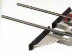
One of the main components of a manual wood carving machine is its guides. You can make them yourself from ordinary bars.
If one guide is used, it must be tightly attached to the base on which all necessary work will be carried out. To make the entire structure more reliable, while eliminating the possibility of the template shifting, it can be additionally secured with side stops.
If you use such a device for a manual machine, which we made with our own hands, you can always make additional grooves in several products.
Homemade guides are:
- T-shaped;
- On hinges, can be folded like a book;
- L-shaped.
The guides, which look like skis, are quite convenient to use. They can be used with any type of hand router, making work with wooden workpieces as precise and clean as possible.
Devices for processing bodies of rotation
 If, when working with such a machine, you have to process certain bodies of rotation, for example, balusters, pillars, and the like, then in this case the process of processing them with a manual milling cutter will become much easier when using another device. It consists of:
- housings;
- a movable carriage on which the tool itself is installed;
- disks with which you can set the required angle of rotation;
- screws that securely fasten the workpieces.
Using such a device, the products will rotate slowly, which will make the processing process more convenient. Thus, you can make a device with your own hands that will become a full-fledged replacement for a lathe.
Compasses

Such devices for a manual milling machine ensure its movement along the required circle. The design of a self-made compass is very simple, it consists of a main part - a rod, which is attached at one end to the base of the tool, and a secondary part - a screw, which is inserted into the hole of a hand router.
A compass with two rods is more efficient in use. By making it from some transparent material, for example, plexiglass, a metric scale can be applied to the surface of the device, which will make its use even more convenient.
Using an angular lever with a scale, copying is carried out on the workpiece being processed. In this case, it will be possible to center the ring on the cutter with your own hands during work. The angle arm with support plate will ensure precise processing of the edges of the part. The design of such a device for working with hand tools consists of a set of probes, a support plate, and protection from chips.
Small extras
Usually, the set of the hand tool itself contains some minor devices that make it easy and convenient to work with parts of non-standard shape. You can always make such devices yourself or slightly improve existing ones to suit your needs and requirements.
Copy rings. Such accessories are ordinary round plates that determine the movement of the device along the workpiece that is installed on a table or other base. The diameter of such rings is selected depending on the diameter of the cutters.
The diameter of the template will also depend on the selected ring. They are selected in inverse proportion - if the diameter of the cutter is larger than the diameter of the ring, then the template is smaller than the finished product, and vice versa.
Devices for working with a manual machine on narrow surfaces will not allow the router to move to the sides, passing exactly in the center of the products.
Devices for creating spikes. Such accessories are most often used in the manufacture of furniture to create connecting tenons on parts.
To carry out a full range of woodworking with a hand router or on a milling table, you need not only conventional devices, such as cutters of various sizes, but also additional devices that will help perform more complex work. The tool must have the ability to create a workpiece of the shape that is needed according to the master’s idea.
Some such devices are included with the device, but if they are not available or if you plan to make it yourself, then additional parts can be made manually. As a rule, they are quite simple to manufacture. In addition to various stops, you can also make a copier for the router with your own hands and install the structure on the frame base.
You can build a milling and copying machine yourself using a hand router. The device can be of different designs, but it has one task - to convey as clearly as possible the movements of the working head along the profile holder to the device that cuts out the material.
It is not always possible to buy a ready-made machine with a copier, so it is often made independently from improvised means. It is recommended to assemble it first; it is difficult to adapt the copier to a serial device; this requires a thorough reworking of it.
Characteristics of the works themselves
Milling cutters equipped with copiers are used for volumetric manipulation and processing of planes. They cope with work that uses three-dimensional forms, engraving of various shapes, drawings, patterns, and inscriptions. They can also do simple milling functions. Such designs are distinguished by their simplicity, but at the same time they are capable of producing surprisingly complex patterns and shapes.
Not only wood, but also cast iron, steel, and non-ferrous metals are suitable for working with such a machine; for this purpose, high-speed tools made of hard alloys are used. On an industrial scale, similar units, but of course larger ones, are used to produce engine blades for aircraft, ship propellers, hydraulic turbine ridges, various models, metal blanks, stampings, cast and pressed parts.

A self-made copier is used when drilling key holes for bolts. They can make frames, grooves, channels of any size in plastic and metal profiles.
But the most interesting thing is that it can be used to mill curved parts, copying them according to a template. The latter allow you to make an exact copy and eliminate the human factor in such complex work. The parts have an exact, perfectly uniform shape.
Identical parts are made using a template; all subsequent parts can be made according to the sample of the first one. For the clearest and most accurate copying, the router is equipped with a copier; such a device is also called a pantograph.
Return to contents
Operating principle and device
Briefly, the principle of operation of the copier is this: using a probe, the contours of the original of the copied object or pattern are traced. The probe is connected to the working plane, at the other end of which the milling cutter is attached, so all movements of the probe are repeated by the milling cutter head.
The machines have a guide system, an electric motor and a chuck for clamping the cutter or router. A simple design is described here.
The standard design consists of:

- working surface and supporting frame;
- milling working head;
- copy probe.
To make a copier with your own hands for a hand router, you will need:
- frame made of wood or metal, if based on a lathe, then such a machine;
- boards and slats, thick plywood, wooden blocks;
- fasteners (bolts, nuts, screws);
- milling cutter;
- a set of wrenches, a hacksaw for cutting the required size of wooden parts;
- metal pipe, guides;
- drills for wood and metal;
- belt drive and electric motor (if it is not manual, but automatic).
The working plane is adjusted in height, the head is equipped with an electric drive motor and a two-stage gear mechanism, which creates two speeds for the router shaft. This is for more complex designs.
If you have a lathe and a manual milling machine, you can build a very good copying machine that will work on large workpieces. This requires a minimum of details.
Making a copier with your own hands is not so difficult.
A hand router is used as the main tool. It is installed on a base made of thick plywood (12 mm), its parameters are 500/200 mm.
A hole is made on it for the sole of the router and mounting bolts. A frame and supports are also made from bars, this serves as additional stabilization and fixation of the tool. Two smaller bars are fixed to the plane of the plywood at the edges. The router is mounted between these two bars with pins (bolts or nails) through holes in its base and made in the plywood.
The platform with its far end slides along the pipe along the structure, that is, it is attached to a block that runs along it. You can take a metal pipe of 1 and ¾ inches. It is fixed between two cubic bars; it seems to hang over the machine with the carriage and cutter. In addition, it is folding. These bars are attached with self-tapping screws to the frame. The pipe is aligned as evenly as possible along the axis of the machine; it coincides with its axis. It is also fitted with two wooden cubes with holes corresponding to it to ensure sliding. It is to them that such a carriage is attached.
Another bar is also attached to the front side of the machine frame, but this is horizontal, and the profile template is fixed on it. It is fixed to two wooden posts vertically on both sides. Its upper part runs exactly along the axis of the machine. When the copier is no longer needed, it is removed and the router and carriage are folded back. A vertical crossbar is attached to the bottom in the middle; it slides along the recesses of the template, copying the relief. This is the copier itself, it is attached with self-tapping screws, in which case it can be removed and replaced or the height adjusted. A template is attached to the block along the facade with self-tapping screws. The platform moves with your hands.
This machine is designed for simple three-dimensional parts such as chair legs, candlesticks, where there are no twisted elements.
Products made from wood are distinguished by their uniqueness and environmental friendliness, which is why they are so valued. But you won’t be able to make a wooden masterpiece with your own hands without a hand router. In addition, it will need accessories with the help of which the craft takes on a given shape.
You can even make them with your own hands, and no special strength or skills are required. Before working with a router, you must first familiarize yourself with each of these devices, as well as learn how they work. In this article we will look at the most necessary designs for a router.
Device - rip fence
This device, as a rule, is already sold along with the router. Therefore, there is no need to develop and create it independently. For reliable support of the processed material, this element is used. With it, the movement of the cutter becomes rectilinear relative to the base surface, which can be a table guide, slats or straight edge part.
This device makes it possible to quickly mill various grooves and process edges while firmly holding the material.
Guide rail
If you need to make a straight cut with a router, then you cannot do without this device. To make it you will need any flat board, for example, you can use a piece of chipboard.
First you need to find out the distance from the edge of the milling base to the center of rotation, and it is always the same. To do this, you need to screw a guide to the unnecessary part of the material and make a test cut. Then you should measure the gap from the edge of the cut to the tire, to which the radius of the cutter is added. As a result, it will be possible to obtain the required value. For example, it is 59 mm, and the diameter of the groove cutter is 14 mm, that is , its radius is 7 mm.
Then you should draw a line for the cut, from which we retreat a distance of 52 mm (59-7), and draw another one. We fix the guide along it and make the cut.
Circle milling
Compasses are used for such purposes. With their help, the router can move around a circle. The simplest of them is a device consisting of a rod, one end of which is equipped with a screw with a pin, and the other is attached to the base of the tool. Of course, it is better to use a compass equipped with two rods.
In general, there are many proprietary and even homemade devices for a router for cutting circles, which differ from each other in ease of use and dimensions. Quite often, compasses have a mechanism changing the radius of the circle. As a rule, it is a screw with a pin at the end that moves along the groove of the router.
When it is necessary to mill a small circle, the pin should be located under the base of the tool. In these cases, other devices are also used, fixed at the bottom of the device base.
But you don’t have to buy a milling compass to cut out circles. Instead, you can use a rip fence. To do this, the device is attached to a groove on the sole. A screw is screwed into it, which is recommended to be equipped with a sleeve so that its diameter matches the size of the hole. That's it, the compass is done. The radius can be adjusted using the stop.
Devices for replication and copying
 To create a series of identical products use:
- Angle lever;
- Copy probes.
There is a scale on the angle lever, the division price of which is 1/10 mm. It allows you to center a stop ring under the cutter, which helps accurately reproduce the shape of the part on the workpiece during copying. It is often equipped with a chip guard and support plate for best edge finishing.
Using copy templates and rings
Copy rings are a round plate with a protruding edge that slides along the base surface along the template. This device provides an accurate path for the cutter to move. Basically, this element is installed on the base of the workbench. At the same time, there is Several methods for attaching it:
- Installation of special antennae in the holes on the sole;
- Screwing the ring into the threaded recess.
Using a template also allows you to achieve more efficient and accurate work. It is attached directly to the workpiece with double-sided tape, and then both parts of the device are pressed to the machine with clamps. Moreover, experienced milling operators advise checking how tightly the ring is pressed to the edge of the template.
In addition, with such a device you can not process the entire edge, but only the corners. Hence, procedure for processing material according to a template- an excellent option for cutting grooves for the product.
Dust removal devices
 Professional craftsmen, in order to ensure dust removal, specially buy a technical vacuum cleaner, which is connected through an adapter with a hose to the router. Moreover, it does not interfere with operating the tool, and the markings and place of processing of the product are always open for visual inspection.
It is very difficult to work without a suction unit. But not everyone decides to make such a purchase, since it is too burdensome in terms of money and, moreover, is not always justified. True, there is another solution; you can get rid of dust with a household vacuum cleaner.
Install between the milling machine and the vacuum cleaner hermetically sealed tank. It will catch the bulk of the dust. It is equipped with an additional hose, and a fabric mesh is inserted inside. Moreover, these designs can be purchased ready-made or made with your own hands. By the way, a homemade device will help a household vacuum cleaner to collect even large construction debris and wood dust.
Slot milling device
This device is used for processing longitudinal grooves on posts, balusters and other rotating bodies. The principle of its operation is as follows. A baluster is installed into the body and fixed. Using a locking screw and a disk, the workpiece is secured in a strictly defined position.
After which the carriage is set in motion and the milling a groove along the length of the product. Then the part is unlocked, rotated to the required angle, locked, and the next groove is created.
Instructions for wood carving with a router
Beginning craftsmen may find working with hand tools difficult because the process of operating them seems difficult. That is why, before you start milling, you need to familiarize yourself with the principle of its operation.
Router assembly
The first step is to check the mounting location of the cutter in the machine; as a rule, a collet chuck is used for this. First, you need to select the desired cutter that matches the size of the chuck. If necessary, you can replace it.
But when deep processing is necessary, an option with an extended shank is used, which is inserted into the chuck hole and secured with a key. This must be done carefully without applying force, otherwise you will overcook, which is not the norm for the correct operation of the router. Although it is worth trying to reach a good stop so that the cutter does not wobble. All that remains is to tighten the spindle lock and you can get to work.
After this, the router turns on, you need to get used to the sound and feel the start. It is often because of surprise that many people start getting married.
Depth selection
 In addition, you will need to install a milling depth limiter. First, the machine is applied to the product from the edge, while the cutter should not come into contact with the material. You will have to press on it until it reaches the required depth, after which position is fixed.
For a more accurate value, use a phased limiter. You can find out its pitch in the manual for the router. In this case, the regulator is rotated by the required number of degrees.
First of all, the required speed is determined. This is done according to the table in the instructions, based on the diameter of the cutter and the material being processed.
If you have never worked with a router before, then it is better to try your hand at a rough version. In addition, this will help you set the necessary parameters directly in processing mode.
It is also advisable to compare the results after moving the tool clockwise and counterclockwise, toward you and away from you. When milling a product around, the correct direction is counterclockwise, and on the flat side, on the contrary, away from you. Then you can start carving the main workpiece.
Wood is one of the main materials that people use in everyday life to make furniture, interior decoration, decorative architectural elements, household and garden supplies and much more.
Wood copying machine.
One or two things can be done with hand tools or using woodworking equipment.
But how to process a large number of completely identical products with the least amount of labor and time? In this case, copying machines will come to the rescue. One of them is a copy-milling machine for wood.
The article discusses its structure and principle of operation, and also offers some advice to those who want to make the device themselves.
Copy-milling machines (CFS) are designed for processing wood parts using the copying method. Types of method:
- contour or 2-dimensional (2-D) milling;
- volumetric or 3-dimensional (3D) copying.
One method or another is used depending on the shape of the product being processed.
The main advantage of copying machines is that it is possible to produce any number of parts with a curved contour, which are a copy of the original copy. They will all be absolutely identical. At the same time, the machine has the flexibility to switch to processing another part, just change the standard.
Therefore, their scope of application is quite wide: from small-scale production to mass production. Along with fairly large machines for industrial use, there are compact desktop devices. Copying machines are used in furniture production, woodworking shops, and carpentry workshops of individual entrepreneurs.
Milling heads (milling cutter) are often used as a working unit in small machines. Its rotation frequency is sufficient to ensure the required surface quality (no chips, splits, burrs).
Examples of processed products
Below is shown a far from complete composition of products manufactured using FSC:
- furniture parts - fronts, headboards, backs, legs of chairs and armchairs;
- interior items - fireplace surrounds, wooden panels, frames, stands;
- souvenir products - figurines, boxes, medallions;
- building structures - framing arched windows, filling paneled doors;
- architectural elements - bas-reliefs, decorative friezes and borders, window casings (slotted or relief), cornice carvings;
- decorative fencing - elements of railings, balusters, screens with ornaments, fence details;
- wooden elements of the weapon - butt, fore-end;
- handles of gardening tools, for example, an axe.
As you can see, the listed parts have significant differences from each other, both in size and shape. If we group them according to the most general characteristics, it becomes obvious that To process parts belonging to the same group, your own design (layout) of the machine is required.
How the copier works
To replicate the product, one of the copies is used, which serves as a template. The head with the cutting tool (mill) is connected into one unit with a copy probe.
With 2-dimensional milling, the probe moves along the generatrix of the copied contour, and the rotating tool repeats this movement, resulting in a copy of the template.
When a volumetric part is milled, the copying tip scans the 3-dimensional model and forces the cutter to move along an equidistant (similar) path. The nature of the movements of copying machines is of 2 types:
- The template and the workpiece are stationary, the cutting head moves in the longitudinal direction, removing a certain amount of material in one double stroke.
- The template and the workpiece (one or more) rotate, and the cutter moves radially along the copier. As a result, it repeats the profile of the copied section. In this case, the cutting unit or part is evenly moved along the longitudinal axis of the product.
A particular type of copying and engraving work is the milling of drawings or ornaments according to a template, which is a pasted paper copy printed on a printer.
As a program for creating a drawing, you can use AVTOCAD, Compass, Word, Paint and others. To avoid tearing the paper, a soft insert (wood or plastic) is inserted into the copying tip.
Choosing the layout of a homemade machine
What you need to know when starting to develop your original device.
First of all, you should determine what parts it is intended for. Next, you should select the forming movements and the number of machine axes. To process flat parts using the contour copying method, 2 axes are sufficient: longitudinal and transverse movement. Parts with low relief require another movement (perpendicular).
However, if the terrain is steep, then the tool axis must be additionally rotated to provide better conditions for processing. That is, there are already 4 axes. In some cases, 5 or more axes will be required. When imagining processing technology in your head, you should consider all possible situations. After the machine has been manufactured, it may be difficult to introduce additional movements.
Finally, the machine must be configured in such a way that control forces are minimal. This means that moving parts should be as light as possible. Think about which layout is better to choose: horizontal or vertical. Firstly, the convenience of work, as well as loading and unloading of workpieces, depends on this. Secondly, with a vertical arrangement, the chips fall directly to the floor or into a trough, and do not accumulate on the base or in the mechanisms of the machine.
The milling head should be selected as high-speed as possible. This is an important factor affecting the quality of processing (the height of the ridges from the cutter decreases).
A few examples
Pantograph

Photo 1: machine for cutting letters.
Used for flat threads. Its design is based on a geometric figure - a parallelogram. One of the properties of this mechanism is that the nodal points describe equidistant curves during movement. Moreover, if the link is lengthened, then its end point will travel a greater distance. This property allows the mechanism to be used for scaling.
The photo shows that the total length with the copying tip at the end is approximately 2 times longer than the side of the parallelogram. This means that the mechanism is magnifying. If you copy a shape with a tip, the cutter will reduce it by 2 times. This will reduce copier errors. Do not forget that the drawing or template is enlarged.
To make a pantograph you will need a purchased router and several dry boards. Apparently it doesn't get any cheaper.
Machine with plane-parallel mechanism

Photo 2: contour milling
The scope of application is also contour milling.
Unlike a pantograph, a curvilinear trajectory is obtained by adding two mutually perpendicular movements. The 3rd axis is used to insert the cutter into the thickness of the part. The weight at the opposite end of the swing frame is designed to balance the system.
Please note a small design flaw: It is better to install the load on a threaded rod to allow for adjustment.
Volume milling machine

Photo 3: volumetric milling
At the bottom of the frame there are 2 rotating attachment points for the copier and the workpiece.
The milling head is mounted on a balanced swinging frame, which during operation moves along mutually perpendicular guides.
Instead of linear bearings or sliding bushings, as in the previous device, roller carriages are used here. The advantage of the design is the open base, which makes chip removal easier.
Duplicarver-2

Photo 4: machine for flat-relief and sculpture carving
Serial machine for flat-relief and sculpture carving. An example of simplicity: they say about such structures - two sticks, two rolling pins. Has 5 controlled axes:
- 4 turns (side arms, rotating frame, head, work tables);
- lateral movement of the head.
Longitudinal movement is obtained by adding two rotations: levers and frame. A German milling cutter with a power of 500 W and a spindle speed of 10 - 30 thousand revolutions per minute is used as a power head. Easily carried by one person (weight - 28 kg).
Duplicarver-3

Photo 5: processing of long-length volumetric threads
2 more rolling pin guides (an additional linear axis) have been added to the previous machine, and the rotary work tables are located vertically. As a result, it became possible to process long volume threads.
Below are some drawings that may be useful in making a homemade device.
Drawing 1 - pantograph device

Drawing 2 - diagram of a router mounted on a pantograph 
Drawing 3 - carriage for installing a router on a flat-bed copier

Video: presentation of a homemade copying machine
Do-it-yourself CNC copying machine - is it possible?
All the devices discussed above are manually controlled, that is, despite the increase in productivity, the person remains chained to the mechanism. This kind of work is quite monotonous and tedious. In mass and large-scale production, copy-milling machines equipped with computer numerical control (CNC) are used. All work on such equipment comes down to loading blanks and removing finished products. As an example, the photo shows a similar machine.
 A copying machine differs from a conventional CNC milling machine by the presence of a programming system. A traditional CNC machine operates from a control program compiled by the operator in a system, for example, ARTCAM, according to a 3-D model, which is developed at the design stage by a design engineer. If the product was created by a sculptor or designer, it must first be digitized, that is, a 3-D model must be created. This work is performed by a software engineer.
On a CNC copying machine, the control program is compiled by the system itself. When installing a copied product, an additional CNC attachment probes the part and creates its 3-dimensional model, from which a control program is automatically generated. Considering the high cost of components, problems with purchasing a CNC system, making a CNC copying machine yourself is something out of the realm of science fiction. It’s easier to make a CNC milling machine (not a copying machine), although not everyone can handle this either.
For those who are going to start their own business, making crafts from wood, as well as for professional cabinetmakers, a self-made copying machine will be of great help. It can be successfully used for the artistic decoration of a country estate, outbuildings, playgrounds and other structures. Jewelry work, it would seem, will be done effortlessly and with high quality.