Installation and instruction manual. Collection and preparation of oil, water and gas at the field. UPSV heater-treater. measuring installations ASMA-t, quantum. control devices "mikon", "sigma". DNS circuits and equipment. Monasteries and monastic peasants of Pom
The process of preparing the produced gas-water-oil emulsion consists of separating from oil and recycling associated petroleum gas, produced water and obtaining commercial grade oil in accordance with the requirements of GOST No. 9965-76. The preparation of the liquid received through oil collection is carried out in several technological stages and depends on the content of associated petroleum gas and the resistance of the gas-water-oil emulsion to the separation of produced water, and physical properties.
Arrived at the booster pumping station (BPS), the gas-water-oil emulsion is stepwise separated from the associated petroleum gas and sent for preliminary water separation to a preliminary water discharge unit (UPW), located either at the BPS site or at a separate site. Depending on the design solutions, preliminary water discharge installations are equipped with technological settling tanks, heaters, apparatus, and pumping equipment.
Let's consider the design and equipment of the booster pumping station for the water treatment unit using the example of the Savuyskoye field.
At BPS-1 UPSV-1, separation, dewatering of well products and its transportation with a residual gas content of 4-5 m 3 /t and water up to 10% are carried out at KSP-2 TsPPN.
At BPS-1 UPSV-1, preliminary discharge of formation water from the liquid is carried out, preparation of formation water and its supply from treatment facilities to the low-pressure water pipeline system for receiving KNS-1.
The gas after the 1st stage of separation is used at KS-44, the boiler room, and Heather-Treaters; excess gas is fed to the flare. Gas from stage 2 is discharged to the flare.
Composition of the equipment of BPS-1 UPSV-1 Savuyskoye field:
S-1/1,2 - separators of the first stage of separation DNS type NGS 1,6-3000-M2, U=100m 3 -2 pcs.;
TS-1,2,3 - three-phase separators "Hitter-Tritter" from the company "SIVALLS" - 3 pcs.;
S-2/1,2 - separators of the second stage of separation BNS (buffer-separator), type NGS 1,6 - 3000-M2, V=100m 3 -2iht.;
G-1 - gas separator, type NGS 1.6-3000-M2, V=100m 3 - 1 pc.;
G-2 - vertical gas separator for preparing fuel gas for Heater-Treater devices and the needs of a boiler room type SCV -500-2-2, V=0.5 m 3 -1 pcs.;
K-1 - condensate collector, volume 4 m 3 - 1 pc.
EM - methanol capacity type EM 1-4-1.0-3 - 1 pc.
EP - capacity of corrosion inhibitor type EY 1-25 - 1 pc.
F-1 - emergency gas flare - 1 pc.
K-2 - condensate collector type EPP-2000-2-K V= 25m 3 - 1 pc.
RO-2, RO-1 - technological reservoirs for the preparation of formation water, type RVS-5000;
R-1 - emergency tank type RVS-5000;
N-1,2,3 - oil pumping station with pumps type TsNS 60-264 (3 pcs.);
BRKH - reagent management unit type BDR - "OZNA" NDU 10/10 for supplying demulsifier with pumps NP-33 "BRAN - LUEBBE";
EP-1,2,3.4 - emergency drainage tanks type EPP-40-2400-2-2 - 4 pcs. with submersible pumps type HB 50/50-4 pcs.;
E-1,2 - tanks for collecting industrial and storm water runoff type EPP 40-2400-2-2, V=25 m 3 with submersible pumps type NV 50/50-2 pcs.;
N-6/1, N-6/2 - pumping station for pumping out produced water with pumps type 1D-315-71 - 1 pc. and pumps 630 1 D90 (2 pcs);
1. Description of the technological process and technological diagram of the installation
1.1. Technological diagram of UPSV at BPS-1 1.1.1. Description of the raw material flow
The watered gas-oil mixture from the metering units is supplied to the additional work unit DNS-1, then through the Du-530 pipeline through electric valve No. 1 it enters the separators of the first stage of separation C - 1/1.2, where primary separation occurs at P = 0.5- 0.75 MPa and temperature t = 30-45°C.
Level regulation in separators S-1/1.2 occurs using control valves No. 8.12, which maintain the liquid level in separators H = 1.2-1.6 m.
Gas from the first stage separators through open valves No. 113, No. 114 enters the gas separator G-1.
The degassed oil emulsion BPS-1 after separators S-1/1,2 through the open valve No. 16 enters the UPSV, while valve No. 18 on the BPS must be closed.
The pre-dehydration process is carried out in three parallel operating three-phase TC devices - No. 1,2,3 (HEATER-TREATER) manufactured by SIVALS (USA).
The oil-gas-water emulsion enters three-phase separators TS - No. 1,2,3 through open valves 28, 30, 32 and through inlet fittings DN=250 located at the top of the tanks.
The liquid phase enters the inlet compartment of the installation onto a flow distributor hood, where the primary separation of gas and free water from the liquid occurs. The released gas rises to the top of the installation and flows through the moisture extractor to the gas outlet pipe. In the moisture extractor, all the liquid in the gas, in contact with the metal mesh, coagulates and merges with the liquid phase down the container. Next, the gas passes through the back pressure valve BPV, which controls the operating gas pressure in the installation and is discharged to oil and gas separators NGS-2/1.2 through open valves No. 9.1, 9.2, 9.3 in the BU, it is also possible to discharge the gas released from the oil to a flare, for which it is necessary to open valve No. 151 and close valve No. 152.
The temperature in the flame tubes is maintained by burning associated gas released from the incoming product flow. If there is not enough gas in the incoming stream to maintain the set temperature, an alternative source of fuel gas is available. Regulators and devices that provide flame and temperature control are installed in the control unit.
A more stable emulsion rises and heats up around the flame tubes, during which additional destruction of the emulsion occurs, coagulation of oil and water droplets. Coagulated water droplets settle and combine with free water at the bottom of the apparatus.
The oil rises higher, coagulating in the middle part of the apparatus, and flows through special partitions, ending up on coalescing filters (coalessors).
Coalescing filters consist of a package of special polypropylene profiled vertical plates located one above the other.
In laminar flow mode, oil droplets rise to the top layer of the coalesser plates. These droplets coagulate and form an oil film on the lower surface of the polypropylene plates. The use of grooved plates located next to each other creates a large coagulation area on which oil droplets collect.
This section encourages more droplet collisions to form large globules of oil.
The collected oil rises upward to the oil phase, and water, due to the difference in density, settles in the lower part of the container. Dehydrated oil continues to rise to the top and flows into the collecting section of the TS devices - No. 1, 2, 3, from where it is removed from the tank through a mechanical valve-regulator and through shut-off valves No. apparatus.
Pre-dehydrated oil, which has passed through three-phase devices through open valve No. 35, enters separator buffers C-2/1.2, where further degassing of oil occurs at a pressure of 0.1-0.6 MPa and a temperature of 30^15 o C. Level in separators C- 2/1.2 is maintained using regulator valve No. 20. After the buffer separators, the degassed oil emulsion is sent to receive pumps N-1/1...3. Electric valves are installed at the pump inlet: ZD No. 16, 9, 5 at the intake, ZD 17, 1, 3 at the outlet. The oil metering unit has two working metering lines and a control line with magnetic induction turbine meters. After measurement, the oil is transported through the open electric valve ZD 78 via a pressure oil pipeline to KSP-2 TsPPN.
In emergency mode, oil is supplied to the emergency tank R-1
by opening valves No. 24 and 43. Pumping oil from the emergency tank R-1
produced by one of the pumps N-1/1...3 through a separate pipeline.
In the event of emergency situations, the installation is transferred to a backup operation scheme in DNS mode. When the TS-1,2,3 devices are stopped, the flow of raw materials coming from the well pads passes through the first stage separators and then through open valves No. 18, 115, 19 and with closed valves No. 16, 17 enters separator-buffers S-2/ 1.2. Next, the liquid is supplied to the intake of external pumping pumps through inlet valves No. 23, 22, 20 and pumped out N-1/1 ... 3 through open flow valves to the oil pumping station No. 17, 1,3, through the metering unit at KSP-2.
The release of the devices, the collection of drainage waste, leaks from the pump seals are carried out in the drainage tank E-6. When the maximum level in the tank is reached, the HB-50/50 pump is automatically turned on, which pumps out the liquid to receive external transport pumps or to the inlet of separators S-2/1,2.
1.1.2. Gas outlet
Associated petroleum gas released in separators S-1/1,2 is directed through open valves No. 113, 114 to gas separator G-1 with a built-in droplet eliminator. As it accumulates, condensate from the gas separator is discharged through valves No. 167, 163 into the drainage tank K-1. The gas separator is equipped with an upper limit liquid level indicator. The pressure is maintained using the regulator valve No. 120/1, which maintains the pressure in G-1 P = 0.75...0.65 MPa. After the pressure control unit, the gas is sent to the gas metering unit. Having passed the flow measurement unit, the gas is supplied to KS-44. The pressure in the gas pipeline is P = 0.6 MPa. The gas released in the three-phase devices TS-1, TS-2 and TS-3 through valves No. 9.1,9.2, 9.3,152 enters the second stage separators S-2/1,2. Gas from buffer separators S-2/1.2 is directed through an open electric valve ZD130 to the flare.
In this case, the pressure in the buffer separators is maintained using control valve No. 131. Part of the gas is taken from the gas pipeline after G-1 and supplied to the fuel gas preparation site. Gas preparation is carried out in a centrifugal gas separator G-2. The condensate released in the gas separator G-2 is collected in container K-2, from where, as it accumulates, it is pumped out through valve No. 204 to receive external pumps. The gas supplied as fuel to the Heather Treater is supplied from the vertical gas separator G-2 at the fuel gas site through open valves No. 206, 207, 194, 193. The gas supplied to the gas boiler house as fuel is supplied from the separator G-2 through open valves No. 200, 119. All devices S-1/1, S-1/2, S-2/1, S-2/2, G-1, G-2, TS-1, TS-2, TS -3 are equipped with safety valves. When the safety valves are activated, gas is supplied to the flare through the pipeline system.
In emergency cases, when gas is discharged from gas separator G-1 to a flare, gas is supplied to gas separator G-2 from the gas pipeline to KS-44.
1.1.3. Discharge from produced water
The water released in the installation from the emulsion near the flame tubes and in the coalescer settles to the bottom of the container and combines with free water. Next, the water moves along the bottom to the end of the apparatus and leaves it through two mechanical valves-regulators for the discharge of formation water.
Then, through open valves No. 74, 73/1, 73, 72/1, 72, through the Du426 pipeline, untreated formation water enters reservoirs RO -2.3 V=5000m3 through valves No. 68, 70, 71 67, 65, where treatment is carried out to the required values. Also, storm drains from tank E-5 enter these tanks through valve No. 168.
After dynamic settling, purified formation water from formation water preparation tanks RVS-5000 No. 2,3 through valves No. 55, 57, 54 by gravity flows to the receiving pumps for pumping out produced water N-6/1,2,3 and then through the formation water metering unit into the low-pressure water pipeline system at KNS-1.
The captured oil from the level H = 8.6 m or 9.6 m through the Du219 pipeline through valves from RO-1.2 No. 77, 49, 56, 69, 52 flows by gravity to the intake pump N-3/1 (TsNS-60 -264) and pumped out to the central pumping station. There is a non-pressure option for supplying captured oil to the emergency RVS-5000 R-1 through valves No. 52, 56, 50, 66, while valve No. 49 must be closed.
To operate the tanks in sequential mode, the design provides for a flow pipeline with valves No. 59, 51. When valves No. 57, 68, 71 are closed and valves No. 59, 51, 54 are opened, water flows from one tank to another sequentially.
To clean the tank, remove sludge from RO-2, RO-1 through the drainage fittings by opening valves No. 58, 53 to the industrial storm sewer, and then into the tank for collecting industrial storm water E-5 V=25 m 3
Liquid from TS devices No. 1, 2, 3 during routine maintenance, as well as in emergency cases, enters the buried tank V-40 m E-1, then is pumped out to treatment facilities, to emergency P-1 or to the reception of oil pumps from the booster station -1.
1.1.4. Reagent supply
For effective stratification of the liquid entering the BPS-1 UPSV-1, a demulsifier is supplied to the inlet pipeline. All demulsifier reagents are dosed in the form of an oil-water reagent emulsion. The demulsifier content in the emulsion is 1...2% by weight.
The demulsifier is prepared using the following technology. The mixer of the reagent block BDR “OZNA-DOZATOR-25” is supplied through an open valve No. 281 with partially dehydrated oil (with a water content of up to 10%) from external pumping pumps and a concentrated reagent by dosing pumps.
The dose of concentrated demulsifier, the amount of oil for preparing the demulsifier solution is supplied based on the volume of liquid entering the site.
The technological scheme for piping the equipment of the OZNA-DOZATOR-25 BDR unit makes it possible to supply a concentrated reagent into the system.
The demulsifier solution is introduced through open valves No. 98, 97 and a check valve into the liquid inlet pipeline before the first separation stage when the BPS is operating in the UPSV mode.
All demulsifier reagents are flammable, explosive and toxic substances that require special precautions when receiving, transporting and filling reagent containers.
When one of the “Hitter-Titter” devices is taken out for preventive maintenance, the water cut of the produced oil increases and therefore at this time the BDR unit pumps a demulsifier into the external transport oil pipeline through valve No. 88/1.
The start-up and installation of the block dosing unit for reagents BRKh must be carried out in accordance with the technical description and operating instructions for the dosing unit for reagents BDR - “OZNA-Doser” PDRK 062841.003 TO of the manufacturer.
1.1.5. System for supplying fuel gas to gas injectors of the heating section
three-phase devices TS-1, 2, 3
Gas for the burners can be supplied from the installation (associated gas released from oil), or from a separate source of the G-2 separator. Gas from a separate source is supplied from the fuel gas preparation site of the Booster Station - 1 through valves No. 206, 207, 194, 193 and valves 152,157,158, which are located at the scrubber tank.
To prevent dripping liquid (oil, condensate) from entering the fuel gas supply system, the gas first passes through a fuel gas scrubber. The scrubber is equipped with a condensate limit sensor, which cuts off the supply of fuel gas when the scrubber is filled with liquid. The scrubber is also equipped with a remote level column and drain valves to periodically drain the collected liquid.
From the scrubber, gas flows to the two main burners through the pressure regulator valve PR2, which reduces the pressure in the system to 0.25 MPa. Fuel gas is supplied to the main burners in the furnace through two parallel shut-off valves XSV2, temperature control valves TC 1 and manual shut-off valves.
Temperature regulator valves TS 1 are controlled by a sensitive element, which is installed near the flame tubes in the installation. Control valves open and close depending on the increase or decrease in temperature in this section and thereby control the supply of fuel gas to the burners of the furnace.
Each installation is equipped with two burners and each of them is controlled by one temperature controller TC 1 and the corresponding firebox. Fuel gas to the pilot burners passes through the gas pressure regulator PR1, which reduces the pressure to 0.11 MPa. The fuel gas to each pilot then passes through the XSV1 shut-off valve and manual shut-off valves, which control the flow of gas to the burners. Each burner is equipped with one pilot. 1.1.6. Emptying devices from products and installing plugs
The release of oil and gas separators of the first and second stages NGS 1/1,2, NGS2/1,2, gas separators G-1,2 is carried out into the underground tank E-1, E-2, K-2 through drainage pipelines connected into a single drainage system.
Drainage from oil pump filters and oil metering units, emptying pumps of liquid for repair work, as well as drainage; from the three-phase “Hitter-Hitter” separator is produced into the underground drainage tank E-5, E-6 (closed drain).
Drainage of gland leaks from oil pumps TsNS 60-264 is carried out into the underground drainage tank E-1.
Pumping of liquid from underground drainage tanks E-1,2,5,6,K-2 is carried out by installed NV 50/50 pumps to receive external pumping pumps.
Installation of standard plugs on oil and gas separators, gas separators, three-phase Hitter-Tritter separators, tanks, pumps, after emptying the product, is carried out on the flanges of the receiving and distributing pipes of the devices.
The diagram of drainage pipelines with the numbering of shut-off valves installed on them is part of the technological diagram of the water treatment unit at the Booster Station-1 of the Savuyskoye field. 3.1.7 Description of the flare system operation
Gas in emergency mode and from safety valves is supplied to the emergency gas flare F-1. The flare installation UFMG 300-"HL" with an automatic remote ignition system was used as a torch.
An expansion chamber of DN 700 mm is installed on the flare line to separate droplet liquid from the flare gas pipeline, carried away along with the gas from the separators of the booster station. The captured liquid from the expansion chamber is collected in an underground tank K-2, from where, when the maximum level is reached, it is pumped out by a submersible pump NV 50/50 to receive external transport pumps. Gas is sent to the flare system in the following cases: - during repairs of KS-44 - in case of a rupture of the gas pipeline from the booster station (in this case, stage 1 gas is discharged
separation by opening electric valve No. 134)
When the safety valves of the devices are activated.
1.2. Description of the UPSV automation system at DNS-1
The automation system DNS-1 UPSV assumes the constant presence of on-duty personnel. This is due to the fact that the switch to operating mode and the necessary changes to operating parameters are made by the operator. Monitoring and management of the technological process of the water treatment plant facilities at the booster pump station-1 is carried out from the operator’s switchboard panel located in the control room of the booster pump station. The accepted degree of automation is carried out using commercially produced instruments and automation equipment. A complete computer system allows for complete control of the operation of the Hitter-Tritter installations. When describing the automation equipment for the “Hitter-Tritter” installations, drawing E 1141900R was used.
1.2.1. Installation of a three-phase Hitter-Ritter separator
The Heather-Treater three-phase separator unit is equipped with mechanical level control valves located on the oil outlet line (CV2) and on the water outlet line (CV1). These valves are opened and closed by water and oil level regulators (floats). As the oil level rises, the oil level float (LC2) rises and mechanically opens the oil control valve. When the water level rises, the water level float (LC1) rises and mechanically opens the water control valve. To pass large volumes of water, the installation is equipped with two water level regulators and two valves. The tank pressure is maintained by a back pressure control valve (BPV1) installed on the gas flow line.
To ensure that liquid does not enter the fuel gas supply system, the fuel gas first passes through a fuel gas scrubber (SCRUB 1). The scrubber is equipped with a high condensate level sensor (LSH2), which cuts off the fuel gas supply if the scrubber is filled with liquid. The scrubber is also equipped with a manual drain valve (HV6), allowing the operator to periodically drain the collected liquid.
From the fuel gas scrubber, fuel gas from the main burner passes through the fuel gas regulator (PR2), which reduces the system pressure to 2.5 kg/cm2. Fuel gas is supplied to the main burners in the furnace through two parallel shut-off valves (XSV2), control valves (TC1) and a manual shut-off valve (HCV3). Control valves (TC1) are controlled by temperature controllers (TC1), the sensitive element of which is installed near the flame tubes in the installation. Control valves (TC1) open and close depending on the increase or decrease in temperature in this section and thereby control the supply of fuel gas to the furnace burners. The fuel gas passes through the gas regulator (PR1), which reduces the pressure to 1.1 kg/cm2. The fuel gas to each pilot then passes through a shut-off valve (XSV1) and a manual shut-off valve (HV1), which control the gas supply to the burners. Each burner is equipped with one pilot.
The pilot burners in both flame tubes are monitored by ultraviolet detectors on the burner control panel (BURNER). If the burner fails, the solenoid valves (XVS1 and XVS2) close.
For subsequent purging and ignition, the alarm on the burner control panel must be reset.
Auxiliary automation equipment includes the following devices:
Inspection gauges CTemia(LGl and LG2) for monitoring the oil level in the installation and determining the level of phase separation between oil and water;
Working pressure gauges (PH and PI2);
Pressure gauges for measuring flue gas pressure (FG);
High and low level sensors (LSH1 and LSL2);
Thermometers (TI);
Temperature sensors at the entrance to the installation and in the installation (TT1 and TT2);
Pressure sensor (PT);
Gas flow sensor (FT);
Oil and gas turbine meters (FM1 and FM2);
Safety equipment includes the following devices:
Safety valves (PSV1 and PSV2);
Protective disk (SH1);
High temperature sensors in the installation (TSH1);
Flue gas high temperature sensors (TSH2);
Fuel gas high and low pressure sensors (PSH1 and PSL);
Scrubber high condensate level sensor (LSH2);
Ignition system with emergency shutdown in case of burner malfunction.
The burner control panel contains the following:
ON/OF switch, which cuts off the voltage entering the panel;
RESET button;
BURNER START button;
BURNER STOP button;
Two serial SPST contacts for “Checking the status of both burners”;
Two serial SPST contacts for "Burner Failure Shutdown";
SPST contact to input a signal from the computer to shut down.
The flame tubes are equipped with fire arresters, which contain the main and pilot burners. A lightning rod and a protective cap are installed on the exhaust pipes
from the rain. The back pressure regulator (BPV1) and measuring tube (FE), necessary for the correct operation of the unit, are mounted on the gas flow line.
The control unit contains lamps, heaters, an exhaust fan, a gas sensor and a thermal detector in case of fire. The air temperature sensor in the control unit measures the temperature in the unit. The heaters are controlled by a sensor that maintains the temperature in the range from 0°C to 1.7°C. The exhaust fan is controlled by a gas sensor. It is launched when the concentration of flammable mixtures in the air is 20% or higher of the lower explosive threshold. Anodes are installed at the bottom of the container to protect the steel surfaces of the device from corrosion.
BIBLIOGRAPHY
1. Oilfield equipment. Directory E.I. Bukhalenko, V.V. Vershkova, Sh.T. Jafarov, E.S.Ibragimov, A.A. Kashtanov, N.G. Kurbanov, O.I. Efendiev.
2. Akulshin A.I., Boyko B.S., Zarubin Yu.A., Doroshenko V.M. Operation of oil and gas wells - M.: Nedra, 1989.
3. Atipaev A.O. Handbook for oil production and well repair specialists - Surgut: Priobya Oil, 1999.
4. Boyko B.S. Development and operation of oil fields - M.: Nedra, 1990.
5. Bukhalenko E.I., Abdullaev Yu.G. Installation, maintenance and repair of oilfield equipment - M.: Nedra, 1985.
6. Methods of combating asphalt-resin-paraffin deposits in wells and oilfield equipment - VNIIOENG: Rosneft, 2003.
7. Rules for conducting repair work in wells. RD 153-39-023-97.
8. Safety rules in the oil and gas industry. PB 08-624-03-St. Petersburg: BiS LLC, 2003.
9. Sereda N.G., Sakharov V.A., Timashev A.N. Oil and Gas Worker's Satellite - M.: Nedra, 1986.
10. Technological instructions for conducting work during oil production, increasing oil and gas recovery from reservoirs and well productivity, and testing wells.
11. Conditions for ensuring the safety of work during current, major repairs and development of wells after drilling.
12. Matveev S.N. Theory and practice of oil production. - SURGUT. Advertising and publishing center "Oil of the Ob Region" of OJSC "Surgutneftegas"; 2003.
13. Well oil production I.T. Mishchenko 2003.
To control field development, it is necessary to measure oil, water and gas flow rates at each well. In addition, you should know the amount of mechanical impurities in the well production. These data make it possible to control the operation mode of wells and the field as a whole, which allows taking the necessary measures to eliminate possible deviations. Thus, an increase in the amount of mechanical impurities in the well production may occur due to the destruction of the bottomhole zone. Therefore, it is necessary to either change the operating mode or secure the bottomhole zone.
Separation and metering installations are often used to measure flow rates. When using them to measure the amount of each component of a well's production, they must first be separated from each other, i.e. a separation process is required. In practice, individual and group separation-measuring installations are used.
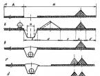
An individual separation and metering installation serves only one well. It consists of one gas separator (ladder), a measuring tank and piping. The well's production flows through the flow line into a gas separator, where the gas is separated from the oil, and then the oil is sent to a collecting manifold or meter for measurement. Gas enters the gas collection network. In the measuring tank, after settling, water and mechanical impurities are deposited at the bottom and are periodically removed through an outlet. The quantity (volume) of well production is measured in a meter. After measurement, the oil is sent to the collection reservoir by a pump (with a pressure collection system).
The amount of gas is measured with special devices and instruments at the outlet of the gas line after the gas separator.
A group separation and metering installation of a gravity system (GSZU) serves several wells. It consists of a gas separator, a meter, a distribution battery (comb) and pipelines.
Products from wells (mass flow, gas lift, pumping) are sent to the distribution battery. When one well is turned on for metering, the production of all other wells is mixed and enters the collecting reservoir without metering.
The measurement is carried out similarly to the measurement in an individual separation-measuring installation. The products from the remaining wells entering the collection reservoir are sent sequentially to the gas separator of the first and second stages, while gas can be taken from each separation stage. Oil from the second stage separator enters the collection manifold.
In modern pressure sealed systems for collecting and transporting well products, automated separation and metering installations ASZGU are used (types ZUG, Sputnik, AGZU, etc.).
The products of oil production wells are supplied to a Sputnik-type metering installation, where periodic measurements of the volume of liquid supplied by the well are carried out, the percentage of water in the liquid and the amount of free gas are determined. Installations of the Sputnik-A, Sputnik-V, Sputnik-B40 and Sputnik-B40-24 types have been designed and are being used. Let's consider the operation of the Sputnik-B40 installation (Fig. 7.6).
It is designed to automatically switch wells to metering according to a given program and automatically measure well flow rates. An automatic oil moisture meter is installed on Sputnik-B40, which continuously determines the percentage of water in the oil flow; automatically using a turbine flow meter (turntable) 15 The amount of free gas released from the oil in the hydrocyclone is measured. The turbine liquid flow meter TOP 1-50 in Sputnik-B40 is installed below the liquid level in the process tank of the hydrocyclone separator.
Using Sputnik-B40, as well as Sputnik-B and Sputnik-A, it is possible to measure separately the flow rates of watered and non-watered wells. To do this, proceed as follows. If, for example, 2 wells (see Fig. 7.6) are watered, and the remaining 12 wells connected to Sputnik supply clean oil, then special check valves 1 are manually closed, and the production of the watered wells along the bypass line through valves 12 is sent to collection manifold 8. The production of wells supplying clean oil is sent to the tank of the multi-pass well switch PSM, from which it enters the collection manifold 6, and then into the anhydrous oil reservoir 23.
The liquid of any well set for metering is directed through the rotary well switch 4 into the hydrocyclone separator 13. At the gas outlet from the separator, a differential pressure regulator 14 is installed, which maintains a constant differential between the separator and gas flow meter 15. The constant differential pressure is transmitted by spool mechanisms 16 and 16 a , from which a constant differential is also transmitted to the piston valve 19.
The amount of liquid is measured from wells as follows. When the float 17 of the level gauge is in its lowest position, the upper fork of the float mechanism presses on the upper protrusion of the spool, as a result of which increased pressure from the regulator 14 is transmitted to the right side of the piston valve 19 and closes it; the liquid supply stops and the turbine flow meter 18 stops working. From this moment on, the liquid level in the separator rises. As soon as the liquid level in the separator reaches its highest position, and the lower fork of the float mechanism presses on the protrusion of the spool 16 a, the increased pressure from the regulator 14 acts on the left side of the piston valve 19 and opens it; the movement of liquid in the system begins, and turbine flow meter 18 counts the amount of liquid passing through it.
To determine the percentage of oil water cut, a moisture meter 20 is installed on Sputnik, through which all well production is passed.
Sputnik-B40-24 has also been developed, which differs from Sputnik-B40 only in the number of connected wells - not 14, but 24 wells can be connected to it. All other data of this Sputnik are the same as those of Sputnik-B40.
The Sputnik-V installation uses volumetric metering of the well fluid supply. It gives more accurate results than measurements using a turbine flow meter if the oil does not have a high wax content. If there is a significant content of paraffin, resins and mechanical impurities, they are deposited in the calibrated container of the measuring device and reduce the accuracy of measurements.
Parameters of installations of the “Satellite” type are given in Table 7.1.
Table 7.1 Parameters of “Satellite” type installations
|
Options | ||||||
|
Number of connected wells | ||||||
|
Working pressure, MPa | ||||||
|
Liquid measurement limits, (m/day) | ||||||
|
Measurement error for liquid, % | ||||||
P  The multi-pass well switch (PSM) is designed for automatic or manual transfer of well production to the metering separator (Fig. 7.7).
Technical characteristics of the PSM-1M switch at in
Working pressure, MPa 4
Pipe diameter, mm.
Input 70
Total day off 150
Zamerny 70
Number of inlet pipes 14
Maximum pressure difference between
measuring pipe and common cavity, MPa 0.3
Position sensor supply voltage, V 220
Position sensor version Explosion-proof Ш1
The switch consists of a steel body 1 with outlet pipes 2, a cover 3 with a measuring pipe 4, a rotary pipe 13 with a movable carriage 15 and a shaft 7, a piston drive with a ratchet mechanism and a position sensor. Movable carriage (see Fig. 7.7 b) consists of a housing 21, a carriage 18, rollers 17 mounted on special axes 22, and a rubber seal 19 sandwiched between the housing 21 and the carriage 18. The movable carriage can move in the rotary pipe. Spring 20 ensures that the carriage is pressed against the body. On the inner cylindrical surface of the body there are two parallel annular grooves with grooves opposite each inlet hole. The rollers of the movable carriage move along these grooves. The depth of the groove and recesses is chosen in such a way that when the rollers move along the groove between the rubber seal 19 and the switch body, a gap is formed, and when the rollers enter the recesses, the seal is pressed against the body by the spring 20, ensuring the tightness of the measuring channel. The tightness of the movable connection of the carriage and the rotary pipe is achieved by a rubber sealing ring 16 (see Fig. 7.7 A). The piston drive 10 with a ratcheting mechanism serves to ensure automatic switching of the well-
:in and consists of a cast iron body 6 mounted on the switch cover, a power cylinder with a piston, a spring and a gear rack that is integral with the piston rod.
Inside the drive housing, on the shaft of the rotary pipe, there is a ratchet 5 on a key 12 and a free-standing gear 11. The gear is pressed against the ratchet by a spring 9 and interacts with the drive rack. Ratchet 5 and gear 11 have beveled end teeth, which ensures one-way engagement when they rotate mutually. When a pressure pulse is applied from the hydraulic drive to the cavity of the power cylinder, the piston with the rod will move and rotate the gear, and with it the ratchet
switch shaft. When the pressure is removed, the liquid from the power cylinder will be squeezed out by the piston. The rack and pinion will move in the opposite direction to its original position.
the rapovik with the shaft will not move. The tightness at the junction of the power cylinder and the cover, as well as in the movable connection of the cylinder and the piston, is ensured by rubber sealing rings. The switch position sensor Ul I PSM serves to monitor the switching process, and the software allows you to remotely set the required well to M measures. The drive housing is closed with a cover 5. To repair the PSM, a puller 14 is used.
The PSM switch works as follows. Upon signal) the hydraulic drive is turned on from the time relay, and the power cylinder is< реключателя подается жидкость под давлением. Жидкость перс м с щает поршень с рейкой, поворачивая через храповой механизм ПО воротный патрубок с подвижной кареткой, который останавливав i11 против отверстия в корпусе переключателя. В этот момент ролики западают в выточки, чем обеспечивается надежное уплотнение М(I ду корпусом и кареткой. Жидкость от скважины через подводят пи патрубок и окна в нем попадает в камеру крышки переключатели И через замерный патрубок в замерную линию.
You can connect the well for measurement manually. To do this, use a special handle to turn the shaft of the rotary pipe! And install it on the required well. The position of the P0V0р01 branch pipe is determined by the arrow engraved on the end face of the shaft. The speed of movement of the rotary pipe is low, and therefore the load on the moving parts and their wear are insignificant 1 and rubber seals are also in favorable conditions.< ключателя - почти все они работают при малых перепадах давлении
When operating the switch, you must keep in mind that
in the carriage assembly, the diameters of the seals are along the body and in the rotation. | pipe are identical and the unit is unloaded. However, with one-sided | High pressure creates a bending force in the rotating tube, which makes switching difficult. Therefore, admission should not be allowed! 11 pressure drops in the carriage seal above 0.5 MPa and above I V | It is no longer possible to carry out switching under these conditions. Under normal operating conditions, pressure drops in the HI cartip seal exceed 0.1 MPa.
In recent years, many companies, in particular conversion companies, have been doing a lot of work in the field of creating and producing equipment for measuring the flow rate of wells.
For example, the UZM mobile measuring unit (developed by IPF Sibnefteavtomatika) is designed to measure, in automatic and manual modes, the amount of liquid, oil and gas produced from oil wells.
The operation of the installation is based on a hydrostatic method for measuring the mass of oil well production, based on the dependence of the hydrostatic pressure of the liquid column on density. The main element for the implementation of this method is a differential pressure sensor, which ensures high reliability of the installation, accuracy, and also simplifies metrological support, since bulky and energy-intensive stands are not required.
One of the advantages of the metering installation is the ability to carry out measurements on both low- and high-flow rates.
wells.
The installation consists of two blocks (technological block, monitoring and control block), mounted on a trailer chassis, which allows it to be transported around the field and connected to wells to perform measurements. The monitoring and control unit houses the control equipment and the operator's workplace. The blocks are heated using electric heaters. The installation is certified by the Gosgortekhnadzor authorities of the Russian Federation as a measuring instrument, certificate No. 0000435. Technical characteristics of the UZM:
Working pressure, MPa, no more than 4.0
Liquid measurement range, t/day 1-400
Reduced gas measurement range
to normal conditions, nm 3 /m 3 40-20 000
Limit of permissible basic relative installation error during measurement, %, no more than:
Liquid mass flow ± 2.5
Gas volume flow ± 5.0
Limit of permissible basic relative error of the installation when calculating the mass flow of oil and water 6.0
In addition to the mobile unit, a stationary ultrasonic unit is also produced, which has similar technical characteristics,
but can work on a cluster of wells, and therefore the installation is additionally equipped with a well switch device ml Nifoldov.
Meters for measuring the flow rate of wells of the SKZh type, developed by NPO NTES (Tatarstan), have become quite widespread in oil fields.
SKZH counters are designed to measure mass flow rate and total mass of a substance at constant and variable flow rates. SKZH counters measure flow rate in tons per day, and the total accumulated mass in kilograms. The measured medium can be a liquid, a gas-liquid mixture, for example, coming from oil wells, solutions of various substances, including pulps with fine particles, liquefied gases. When measuring the mass of a liquid in a gas-liquid mixture with a meter I, in most cases, no preliminary separation into liquid and gas is required. Meters are installed at the mouth of a producing well, at a group metering installation, at an oil collection and preparation unit, in control and regulation systems of technological processes. The meter consists of a chamber flow converter! (KPR) and the BESKZH mass calculator unit. The CPR of the SKZH meter consists of a housing and, depending on the standard size, one or two measuring blocks.
Measuring units are explosion-proof< уровнем взрывозащиты «взрывонепроницаемая оболочка» и Moryi эксплуатироваться во взрывоопасных условиях. Он имеет норми руемые метрологические характеристики, его конструкция унифи цирована под все корпуса КПР, унифицирована под все корпуе.1 КПР, что позволяет с минимальными затратами производить замен \ измерительной части КПР в процессе проверки его метрологических характеристик или ремонта. Для измерения одновременно двух по токов жидкости в газожидкостной смеси рационально использован счетчик СКЖ, имеющий индекс модификации «Д». При этом в ОД ном из потоков допускается отсутствие газовой фазы.
For the meter to operate, it is necessary to have free gas in its feed. Therefore, the meter is most suitable for measuring substances containing associated gas that can be released in the meter body.
Information about liquid flow, the accumulated mass of liquid passing through the chamber flow transducer, the presence of emergency situations during the operation of the meter is processed, accumulated and output to the display or to an external network in the mass computer unit. Calculators have an indicator for displaying information or an information reading device that allows you to read the accumulated information on the calculator and then view it on a PC. The computer produces a standardized pulse output signal for transmitting information to the telemetry system, and also has an RS-232 and RS-485 interface, which makes it easy to integrate it into any automated monitoring and control systems. The versions of the BESKZH-2M and BESKZH-2MS computers have an archive of the meter’s operation history, hourly, up to 7 days deep, and daily, up to 3 months deep. The main relative error in converting the number of input pulses into a mass number for each channel of the calculator is no more than ± 0.1%.
The meters are produced in accordance with TU 39-0147.585-010-92, entered into the state register under No. 14189-94 and have a Gosstandart certificate RU.C.29065.A No. 7T22 and a Russian Patent. Technical characteristics of SKZh meters are presented in Table 7.2.
The meter design is explosion-proof, the hydrogen sulfide content in the measured liquid at an operating pressure of 4 MPa is no more than 0.02% by volume.
Currently, in many oil and gas producing regions of the country, mobile measuring units of the ASMA type are used. The ASMA-TP installation is designed for metrological control of oil well productivity measuring instruments (Sputnik AGZU) and high-precision measurements of daily liquid, oil and water flow rates by direct measurement of liquid mass and volume of associated petroleum gas. The installation consists of a block with technological and hardware compartments located on a two-axle car trailer.
Table 7.2
Technical characteristics of SKZH
|
Options | |||||||
|
Flow measurement range, t/day: on the first channel on the second channel |
Up to 120 No |
House Do 61 |
|||||
|
Maximum working pressure, MPa | |||||||
|
Allowable value of kinematic viscosity of liquid, m 2 /s | |||||||
|
Permissible limit of change in gas factor, | |||||||
|
Relative errors of the meter in the measuring range, % no more | |||||||
|
Power supply |
AC 50 Hz 220 V |
||||||
|
Meter weight, kg | |||||||
The mass of the liquid is determined by weighing the empty and filled containers and measuring the accumulation time; the amount of associated gas is measured by two Agat gas meters and a diaphragm complete with the Sapphire-22DD device. Depending on the value of the gas factor, the volumetric flow rate of associated gas can be measured by any of three meters, or by two or three simultaneously.
The hardware compartment contains a control station based on a programmable controller. The measurement result is displayed on the display of a laptop computer, the measurement protocol is printed on a printer.
The ASMA-T installation has a similar device and is located on the car chassis. In the installation code type ASMA-T-03-400
03 - location on the chassis of the Ural-4320-1920 vehicle; 400 - maximum well flow rate measured by the installation,
To measure the flow rate of wells with a high gas factor, a mobile separator is used, in which gas is preliminarily separated and measured. The liquid with a residual gas content is supplied to the ASMA-TP(T) charger for measurement in normal mode.
The operating principle of ASMA-type installations is based on direct weighing of the liquid (oil-water-gas mixture) of the well in named mass units, followed by the controller calculating the daily flow rate of liquid, oil and water. Water content is measured using a VSN-BOZNA moisture meter. The daily volume of associated gas is measured by a gas meter of the AGAT-1M type, and the measurement results are brought to normal conditions in the controller.
Mass measuring installations consist of technological and equipment compartments located in block containers, which are mounted for transportable ASMA-T installations on the chassis of an off-road vehicle, for stationary ASMA installations - on a single base.
The technological compartment is made in class B-1a, where the formation of an explosive mixture of category II A of group TZ is possible. The design of the instruments in the technological compartment is intrinsically safe and explosion-proof. Technical characteristics of ASMA installations are presented in Table 7.3.
Parameters of the measured medium:
working pressure, MPa, no more than 4.0
viscosity, cSt, no more than 500
volume fraction of water,%, no more than 99
mass fraction of sulfur,%, no more than 2
mass fraction of mechanical impurities, %, no more than 0.05
determination error, %, no more:
average daily liquid flow rate - 2.5
volume of associated gas - 6.0
water cut:
Table 7.4
Technical characteristics of the ASMA installation
|
Installation modification |
Measurement range |
Number of wells connected to the installation |
Overall dimensions, mm, no more |
Weight, kg, |
|||
|
By liquid | |||||||
|
NO-8,10,14-180MP | |||||||
|
MO-400-MZPK-4, 6, 8, 10, 12 |
4; 6; 8; 10; 12 | ||||||
Notes:
PC - presence of switching valves
MP - presence of a multi-way switch
MZPK - presence of a module of shut-off and switching valves.
JSC "Surgutneftegas" operates transportable metering units.
The transportable mass-measuring installation “ASMA-T-03-400-300” is designed to determine the daily flow rates of liquid, oil and water by measuring the mass of liquid (oil-water-gas mixture) and the volume of associated gas from oil wells.
The scope of application of the installations is oil and gas fields.
The installation consists of technological and equipment compartments located in a block container, which is mounted on the chassis of an off-road vehicle with an air gap between the compartments of at least 50 mm.
Medium being measured - liquid (oil-water-gas mixture):
Working pressure up to 4.0 MPa
Temperature from minus 10 to plus 50°C;
Viscosity up to 500 cSt;
Corrosion rate, no more than 0.2 mm/year.
The climatic design of the unit is UHL1, but for operation at ambient temperatures from minus 43 to plus 50°C and relative humidity of 98% at a temperature of 15°C.
Specifications:
Flow rate of the well connected to the installation:
By liquid, t/day from 0.1 to 400
According to the gas released under operating conditions, reduced to
normal conditions, m 3 /day up to 300,000
Relative error in measuring liquid mass
(gas-liquid mixture), no more, % 2.0
Relative error in determining the daily average
liquid flow rate, no more than, % 2.5
Relative error in determining the associated volume
petroleum gas brought to normal conditions, no more than 5.0
Relative error in determining oil moisture content in subranges:
a) from 0 to 60% (water-in-oil emulsion), % ±2.5
b) over 60 to 100% - ±4.0%.
Number of wells connected to the installation, 1
Diameters of nominal passages of inlet and outlet pipes, m 50
Pressure loss at maximum liquid flow, no more, MPa 0.02
Voltage, V 380 / 220
Frequency, no more, Hz 50 ± 1
Installed power, no more, kVA 20
Overall dimensions, no more than, mm 9860х2500х3960
Weight, no more, kg 16850
Figure 1 – Transportable mass measuring installation
ASMA-T-03-400-300:
1 – handrail to the stairs; 2 – screw support; 3 – drainage tank; 4 – shoe; 5 – box for screw supports; 6 – grounding box; 7 – pipeline box for connection.

Figure 2 – Sputnik-A product measurement installation
The AGZU premises belong to hazard class B-1a. Hazard Class
determined from the classifier reference book and applied to the AGZU premises.
Also, the sign in front of the entrance to the AGZU should indicate the time
ventilation, last name, first name, patronymic of the persons responsible for the serviceable and fire safety condition - all this data must be painted in bright paint in a visible place in the AGZU premises.
The installation of the switchboard room must be located at least 12 m from the metering and switching installation. Before entering the AGZU, you must turn on the fan for 5 - 10 minutes.
During a long stay inside the installation, when carrying out work with forced oil spills, the fan must operate continuously.
In the absence of electricity, ventilation of the installation is ensured by opening both doors.
On the measuring switching installations the following inscriptions are written in red paint: “FLAMMABLE”, “TURN ON VENTILATION
Inside the AGZU, the numbers of wells connected to the installation must be painted; there must be an operator’s log in which entries should be made after taking measurements. There must be a connection diagram for the pressure vessel and extracts from the instructions for safe operation and fire safety.
During work, the oil and gas production operator must comply with the requirements of this instruction, fire safety rules and personal hygiene rules, and the production culture in the work areas entrusted to him.
TECHNICAL CHARACTERISTICS PURPOSE AND DEVICE OF AGZU
The automated group installation “SPUTNIK” AM-40-10-400 or AM-40-14-400 is designed for measuring periodic changes in the amount of liquid produced from oil wells and for subsequent determination of well flow rate.
The installation monitors the operation of wells based on the presence of fluid supply and separate collection of watered and non-watered oil.
SAFETY REQUIREMENTS WHEN PERFORMING WORK
Before entering the AGZU room to take measurements, the operator must turn on the ventilation or naturally ventilate the room for 15-20 minutes.
Table 2 - Basic technical data
| Maximum flow rate of one measuring well | t/day | |
| The limit of permissible relative error in the operational measurement of the amount of liquid, | % | no more + 6,0 |
| Number of connected wells per measurement | PC. | 10 - 14 |
| Operating pressure | kg/cm 2, | no more than 40 |
| Working environment temperature | o C | +5 о С - +70 |
| Power supply for pneumatic circuits: | ||
| gas pressure | kg/cm 2 | no more than 40 |
| pressure drop between gauging separators and common manifold | kg/cm 2 | 0,3 – 1,2 |
| Power supply of electrical circuits | type of current | variable |
| voltage | 380 / 220 V | |
| frequency | Hz | 50+1 |
| power consumption | kW, | no more than 10 |
| Ambient temperature | o C | +50 o C |
| Design of measuring and switching installation devices | explosion-proof | |
| Room class of metering and switching installation | B – 1a | |
| Panel room design | ordinary |
DEVICE AND OPERATION OF THE INSTALLATION
The installation diagram works as follows:
Well manifolds are connected to the branch pipes of the metering and switching installation through check valves.
The well production enters the multi-pass PSM well switch. From the switch (PSM) of the wells it is sent to the hydrocyclone head of the measuring separator, where the primary separation of gas from liquid occurs. This is necessary for more accurate measurement of the volumetric flow rate of the well.
The production from the remaining wells enters the common pipeline with the valve open.
The amount of liquid squeezed out of the separator by gas is measured by a counter TOP – 1 – 50.
The flow control device in the metering separator ensures a cylindrical passage, i.e. along the full cross-section of the liquid pipe, through the meter TOP – 1 – 50 at a constant speed, which allows measurement in a wide range of well flow rates with a small error.
The TOP – 1 – 50 counter generates pulses to the control and display unit after 50 meters of liquid have passed through the counter. In addition, the counter has a scale with a pointer and a mechanical integrator.
Alternate switching of wells to the PSM switch is carried out using valves.
The installation can operate in three modes:
1. Through a manually controlled measuring separator.
2. Through an automatically controlled measuring separator.
3. Bypass operation.
The measurement time is set depending on the specific conditions of well flow, production methods, and the state of field development. In each individual case, it is agreed with the engineering and technical personnel of the production department.
The flow rate is calculated using the formula:
Q = 1440 --------- KU (1)
Q – daily flow rate, t/day. ;
Н1 – meter reading at the beginning of measurement, m 3
H2 – meter reading at the end of measurement, m 3
T1-T2 – measurement time, min
K – meter correction factor
U – specific gravity of oil, t/day.
When transferring a well to bypass operation:
Open the valves of the 1st row;
Close the valves of the 1st row, install the carriage with the manual control handle between the two trunks;
Relieve pressure.
AUTOMATED MOBILE MEASURING UNITS
OJSC “Surgutneftegas” operates the following types of transportable metering units:
ASMA-TP is designed for metrological control of oil well productivity measuring instruments (Sputnik AGZU) and high-precision measurements of daily liquid, oil and water flow rates by direct measurement of liquid mass and volume of associated petroleum gas. The installation consists of a block with technological and hardware compartments located on a two-axle car trailer.
The mass of the liquid is determined by weighing the empty and filled containers and measuring the accumulation time; the amount of associated gas is measured by two “Agat” gas meters and a diaphragm complete with the “Sapphire-22DD” device. Depending on the value of the gas factor, the volumetric flow rate of associated gas can be measured by any of the three meters, or by two or three simultaneously.
The hardware compartment contains a control station based on a programmable controller. The measurement result is displayed on the display of a laptop computer, the measurement protocol is printed on a printer.
The ASMA-T installation has a similar device and is located on the car chassis. OJSC “Surgutneftegas” uses installations of the ASMA-T-03-400 type, where:
03 - location on the chassis of the Ural-4320-1920 vehicle;
400 - maximum installation capacity t/day.
To measure the flow rate of wells with a high gas factor, a mobile separator is used, in which gas is preliminarily separated and measured. The liquid with a residual gas content is supplied to the ASMA-TP (T) charger for measurement in normal mode.
The OZNA-KVANT-3 installation is a technological and hardware unit located on a car trailer. The operating principle is based on measuring the liquid level in a calibrated container using a Sapphire-22DD differential pressure sensor and filling time.
The hardware block contains a Sirius control station that processes information from sensors. Water cut is calculated automatically by calculation.
DRILLING OIL AND GAS WELLS
A borehole is a cylindrical mine opening of relatively small diameter and long length. The drilling rig, capable of reaching a depth of 15,000 m, was designed and built at Uralmash.
The main drilling processes are: 1) destruction of rock at the bottom of the well; 2) removal of destroyed rock from the face to the surface; 3) securing unstable well walls.
Mechanical drilling methods create stresses in rocks that exceed their strength limit. Mechanical methods of destruction of rocks using rock-cutting tools include: shallow vibration drilling, rotary, rotary impact and percussion drilling. Vibratory drilling and vibratory immersion of soil carriers into soft rocks is carried out to a depth of 25 - 30 m. Surface (mechanical) and downhole (hydraulic and pneumatic vibrators) are used as vibrators.
Rotary percussion drilling is used in hard rocks. With the help of hydraulic and pneumatic hammers, up to 1500 - 2000 blows per minute are applied to a crown or chisel rotating under load. Pneumatic hammers operate from the energy of compressed air, hydraulic hammers - from the energy of a liquid jet.
Impact drilling is carried out by hitting a bit that is dropped to the bottom of a certain height. To increase the impact force, a striking rod is attached to the bit. With the help of a rope lock, the percussion instrument is rotated to a certain angle after each blow. This allows you to strike a new area of the face. Therefore, this type of drilling is called rotary impact drilling, and depending on how the impact tool is lowered into the well, it is called percussion-rope or impact-rod.
Unlike percussion-rod drilling, percussion-rope drilling is carried out without flushing, and the rock destroyed in the face has to be removed after each series of impacts with a special tool - a bailer. The bailer is lowered on the bailer rope after lifting the impact tool. When hitting the face, the bailer valve lets the destroyed rock (sludge) inside, and when lifted, it lowers into the seat and seals the bailer body.
Rotary drilling can be done without flushing or with flushing or purging of the well. Rotary auger drilling is performed without flushing. The removal of destroyed rock to the surface is carried out by a screw column, which is a conveyor. The auger column consists of separate interconnected links - augers, which are a pipe with a steel strip welded to it in a spiral. High-speed auger drilling is used in soft, non-sticky rocks.
Slow rotary drilling is also used when drilling soft rocks - with spoons, coils, drilling soil carriers to a shallow depth.
Rotary drilling of deep wells is usually carried out with flushing of the bottom of the well or with blowing with compressed air. The flushing fluid not only cools the drilling tool and cleans the bottom of cuttings, but also secures the walls of the well against collapses and water absorption. If the rocks are unstable and the clay cake does not secure the walls of the well, then other methods of securing them are used.
Drilling with flushing or purging is divided by the nature of the drive into drilling with motors on the surface, when rotation of the rock-cutting tool is transmitted through the drill string, and downhole motors. The downhole motor is located directly above the rock cutting tool, and the drill pipes, as a rule, do not rotate during the drilling process.
Downhole motors can be hydraulic or electric. Hydraulic downhole motors are called turbodrills, and electric motors are called electric drills. The advantage of downhole motors is that all the engine power is transferred to the rock cutting tool; no energy is wasted on rotating the drill string.
The turbodrill consists of a rotating and stationary system. The rotating system is connected to the bit and consists of a shaft and turbine wheels (rotor disks). The fixed system consists of a housing and guide wheels (stator disks). The turbodrill body is connected to the bottom of the drill pipe string using an adapter.
In a turbodrill, the energy of the fluid flow is converted into mechanical energy of shaft rotation.
An electric drill is a submersible electric motor mounted on top of a long sealed cylinder filled with oil. Electricity is supplied from the surface through a cable laid inside the drill pipes. The ends of the cable, embedded in drill joints, are automatically connected when screwing the drill pipes into a string.
During rotary drilling, the rock is destroyed with the help of cutting and abrasive tools (cutting bits; pico drills; diamond bits; ring bits - diamond, carbide) or crushing tools (cone bits).
Rotary drilling is divided into drilling without coring, in which the rock face is completely destroyed, and core drilling (with core sampling), in which the rock face is destroyed in a ring, as a result of which the central part of the face remains undestroyed in the form of a column of rock (core), from which This is where the name comes from - core drilling.
Depending on the rock-cutting tool used, different face configurations are obtained - solid, circular, stepped, etc.
Fixing unstable well walls is achieved:
1) creating hydrostatic pressure of the flushing fluid (water, clay solution, etc.) filling the well;
2) the formation of a dense clay cake when flushing the well with clay and other solutions;
3) installing a casing string in the well;
4) by the method of electrochemical fastening.
|
DEVELOPED |
Federal State Unitary Enterprise State Scientific Metrological Center All-Russian Research Institute of Flow Measurement (FSUE SSMC VNIIR) |
|
PERFORMERS: |
Nemirov M.S. - Candidate of Technical Sciences, Silkina T.G. |
|
DEVELOPED |
Ufa Engineering and Metrology Center MOJSC "Nefteavtomatika" |
|
PERFORMERS: |
Nasibullin A.R., Fatkullin A.A. |
|
DEVELOPED |
Interregional Open Joint Stock Company MOJSC "Nefteavtomatika" |
|
PERFORMERS: |
Mikhailov S., Khalitov A.S. |
|
APPROVED |
|
|
REGISTERED |
|
|
INTRODUCED FOR THE FIRST TIME |
Date of introduction 2003-03-01
This recommendation applies to the mass-measuring installation ASMA (hereinafter referred to as the installation), stationary or transportable, designed for measuring average daily flow rates of liquid, oil and water and the flow rate of associated gas of oil wells, and establishes a methodology for initial and periodic verification of the installation.
Intervalidation interval: no more than one year.
1. Verification operations
When performing verification, perform the operations specified in Table 1.
Table 1
2. Verification means
2.1. When performing verification, the verification tools specified in Table 2 are used.
2.2. Measuring instruments used during verification must be verified by the State Metrological Service and have valid verification certificates or verification stamps.
2.3. It is allowed to use other similar verification means that ensure the determination of the metrological characteristics of the installation with the required accuracy.
3. Safety and environmental requirements
3.1. When performing measurements, comply with the requirements defined by the following documents:
- “Fire safety rules for the operation of enterprises of the USSR State Committee for National Oil and Gas”;
Safety regulations for repair and electromechanical work, approved and taking into account the specific conditions of specific oil fields;
- “Rules for technical operation of consumer electrical installations” (PTE);
|
Verification tools and their metrological characteristics and regulatory documents |
Quantity |
Used to determine measurement error |
Note |
|||||
|
Masses of fluid |
Fluid flow |
Associated gas consumption |
||||||
|
with turbine meters and diaphragms |
with vortex counters |
|||||||
|
Weight KGO-IU-20, weighing 20 kg, permissible deviation limits: ± 1 g, GOST 7328-82 |
||||||||
|
Set of weights KG-2-5, weighing 5 kg, permissible deviation limits: ± 1 g, GOST 7328-82 |
||||||||
|
Meteorological thermometer, measurement range (0 - 100) °C, GOST 112-78 |
||||||||
|
Aspiration psychrometer, TU 25.1607.054 |
||||||||
|
Aneroid barometer type BAMM-1, TU 25-04-1838 |
||||||||
|
Flow converter with permissible basic error limits: ± 0.5% and measurement range (2 - 16) |
Hydraulic stand included |
|||||||
|
Standard measuring tank of the 2nd category according to GOST 8.400-80 with a capacity of 1000 dm 3 with limits of permissible basic error: ± 0.1% |
||||||||
|
Hydrometer type AMV-1, GOST 18481-81, limits of permissible absolute error: ± 1.0 kg/m 3 |
||||||||
|
Pressure gauge, accuracy class 1.5, GOST 2405-88 |
||||||||
|
Liquid thermometer type A with a measuring range (0 - 50) °C and a division value of 0.1 °C, GOST 28498-90 |
||||||||
|
1st class flasks, cylinders, GOST 1770-74 |
||||||||
|
Low-frequency signal generator G3-102 with a frequency range (20 - 20000) Hz, GOST 22261-94 |
||||||||
|
DC power supply B5-30 with instability: ± 0.01%, TU 3.233.220 |
||||||||
|
Resistance magazine R4831, accuracy class 0.02, TU 25-04.296 |
||||||||
|
Universal voltmeter V7-16 with measurement range (0 - 1000) V, TU 2.710.002 |
||||||||
|
Electronic counting frequency meter 43-33 with a range of measured frequencies from 10 Hz to 10 MHz, E32.721.092.TU |
||||||||
|
Reference resistance coil P331 with a nominal resistance of 100 Ohms, accuracy class 0.01, TU 25-04.3368-78E |
||||||||
|
Electronic stopwatch with permissible absolute error limits: ± 1 s |
||||||||
4. Verification conditions
4.1. The installation is verified in accordance with GOST 8.395-80 under the following conditions:
|
Ambient temperature, °C |
|
|
Liquid temperature, °C |
|
|
Operating pressure at the stand, kg/cm 2 |
|
|
Change in liquid temperature in the installation during filling of the measuring container, no more than, °C |
|
|
Change in liquid consumption during filling of the measuring container, no more than, % |
|
|
Relative humidity, % |
from 30 to 80; |
|
Atmospheric pressure, kPa |
from 84 to 106; |
|
AC power frequency, Hz |
|
|
Device supply voltage, V |
|
|
Lack of vibration, shock, magnetic field (except the earth's). |
5. Preparation for verification
5.1. Check the availability of valid certificates of verification of measuring instruments or imprints of verification marks.
5.2. For a transportable installation option, check the installation position using a plumb line and, if necessary, level it using screw supports.
5.3. Check the presence of an equal diametrical gap between the surfaces of the support and the guide of the measuring tank and, if necessary, carry out its alignment in accordance with the operational documentation (hereinafter - ED) of the installation.
5.4. Before determining the measurement error of liquid flow (during initial verification), perform the following operations:
Connect the installation to the test bench (hereinafter referred to as the stand) according to the verification scheme in accordance with Figure A.1 of Appendix A;
Check the tightness of the system consisting of the stand, installation and connecting pipelines. To do this, set the highest flow rate according to the flow converter of the stand, turn on the “Cascade” control station (hereinafter referred to as the control station), included in the installation kit, and the stand pump, and perform at least two measurement cycles using the control station (in manual mode). No drops or leaks of liquid are allowed through oil seals, flange, threaded and welded joints when observed for 5 minutes. Turn off the stand pump and empty the measuring container to the minimum level using the installation pump;
Enter the number of measurement cycles (k = 10) using the control station operator console program (hereinafter - PPO);
For a stationary installation, the correct operation of the downhole switch is checked according to its ED.
5.5. Before determining the measurement error of associated gas flow, connect the installation to a stand (for initial verification) or to a well (for periodic verification), set the number of cycles (k = 10) and, depending on what measuring instruments are used in the installation for measuring associated gas flow , perform the following operations:
5.5.1. For an installation equipped with restrictive devices (diaphragms), when the power to the control station is turned off, the outputs of the differential pressure, pressure and gas temperature converters are disconnected and a set of measuring instruments is connected to the station inputs in accordance with Figure A.2 of Appendix A.
5.5.2. For an installation equipped with turbine flow converters (hereinafter referred to as TFC), disconnect the outputs of the TFC, pressure and temperature converters when the power to the control station is turned off and connect a set of measuring instruments to the station inputs according to Figure A.2.
5.5.3. For an installation equipped with vortex gas meters (hereinafter referred to as SVG), the outputs of the gas flow sensor (hereinafter referred to as DRG) are disconnected when the power to the control station is turned off and a set of measuring instruments is connected to the inputs of the control station in accordance with Figure A.3 of Appendix A.
5.6. Before determining the measurement error of water content, connect the installation to a stand (for initial verification) or to a well (for periodic verification), set the number of cycles (k = 10), disconnect the outputs of the crude oil moisture meter converter (hereinafter referred to as VCH) when the control station power is turned off, and connect a set of measuring instruments to the station inputs according to Figure A.3.
5.7. Prepare measuring instruments for work in accordance with ED.
5.8. The control station is turned on, the software is launched according to the operator’s manual included in the ED installation kit, and power is supplied to the measuring instruments.
5.9. Check the correctness of coefficients and constants entered into the software according to the operator’s manual.
6. Conducting verification
6.1. Visual inspection
When conducting an external inspection, the following operations are performed:
Establish compliance of the completeness and markings of the installation with technical documentation;
Check the installation units for mechanical damage to surfaces, violations of the integrity of protective coatings and other defects.
6.2. Testing
6.2.1. Check the sensitivity of the weighing system of the installation with tare weight in the “Calibration” mode, set using the software, as follows:
6.2.1.1. Place weights weighing 3.0 kg on the container and record the average value of the gross mass (M Bg), determined by the PPO;
6.2.1.2. Remove the weight and record the value of the tare mass (M Tg);
6.2.1.3. Check the fulfillment of the condition:
m = M Bg - M Tg? eleven)
where M Bg is the gross mass when there is a load on the container, kg;
M Tg - tare mass when there is no load on the container, kg;
m is the mass of liquid simulated by a set of weights, kg.
6.2.1.4. Repeat operations according to 6.2.1.1 - 6.2.1.3 at least four times;
6.2.1.5. If condition (1) is not met in two out of five cases, the cause of the lack of sensitivity is found out and eliminated.
6.2.1.6. Place weights weighing 60 kg on the container and repeat operations according to 6.2.1.1 - 6.2.1.5.
6.2.2. When testing the installation, before determining the error in measuring liquid flow rate on the stand, perform the following operations:
Set the water flow rate equal to (30 ± 5)% of the maximum flow rate for the installation;
Switch the installation into the liquid flow measurement mode;
Perform at least seven cycles of measurements to stabilize the water temperature;
Check that the fluid flow indication is correct.
6.2.3. When testing the installation, before determining the measurement error of the volume of associated gas and water content, perform the following operations:
Check that the software is loaded correctly;
Signals from differential pressure, pressure, gas temperature, TPR, SVG and VSN transducers, simulated using a current setter and generator, are supplied to the inputs of the control station, according to Figures A.2, A.3, and the passage of signals is checked by comparing the current values and the number of pulses, measured by the control station with specified values.
6.3. Determination of the measurement error of liquid mass
When determining the error in measuring the mass of a liquid, the relative error in measuring the mass of a liquid is determined in the “Calibration” mode, specified using the software. The installation is connected to a hydraulic stand (for initial verification) or to a well (for periodic verification).
Determining the measurement error of liquid mass is based on comparing the mass values measured by the installation:
With a known value of the mass of standard weights;
With the value of the mass of liquid poured into the container, determined indirectly using a measuring stick and a hydrometer.
To determine the measurement error of liquid mass, perform the following operations indicated in Table 3.
Table 3
|
During initial verification |
During periodic verification |
|
6.3.1. Empty the measuring container using a pump. |
|
|
6.3.2. Weights weighing 60 kg are installed or suspended on the container. |
|
|
6.3.3. The average gross mass (M B) from the PPO protocol is recorded. |
|
|
6.3.4. Remove the weights from the container and record the average value of the tare mass (M T). |
|
|
6.3.5. Repeat operations according to 6.3.2 - 6.3.4 at least four times. |
|
|
6.3.6. Turn on the stand pump and fill the container with water to the set point for the maximum mass entered using the PPO: (M max = M T + 300) kg. |
6.3.6. Fill the measuring container with oil weighing at least 200 kg. |
|
6.3.7. The tare mass is recorded using the PPO in the “Calibration” mode. |
6.3.7. perform operations according to 6.3.2 - 6.3.4. |
|
6.3.8. A portion of water with a volume of 100 dm 3 is poured into a measuring cup from a container, the gross mass is recorded using a PPO and the density of water (? in) is determined with a hydrometer. |
6.3.8. Drain 100 kg of oil from the container using a pump. |
|
6.3.9. The average values of gross mass and tare mass 1 (M B and M T) are recorded. |
6.3.9. Perform operations according to 6.3.2 - 6.3.4. |
|
6.3.10. Consecutively pour two more portions of water of 100 dm 3 into the measuring cup, recording for each portion the average values of the container weight, gross weight and density of water. |
6.3.10. Empty the measuring container using a pump. |
|
6.3.11. Repeat operations according to 6.3.6 - 6.3.10 at least four times. |
|
1 When draining water from a container, a protocol for gross weight and tare weight appears on the PPO monitor in the “Calibration” mode, but in the left column (tare weight) the initial mass value is noted, and in the right column (gross weight) the mass value obtained after draining . Therefore, in the verification protocol, the smaller value (obtained after draining) is recorded in the column where the container weight is, and the larger value (before draining) in the measuring cup is recorded in the gross mass column.
6.4. Determination of liquid flow measurement error
Determination of the error in measuring liquid flow rate by the installation is carried out on a hydraulic stand by comparing the results of measuring liquid flow rate by the installation and the flow transducer (hereinafter referred to as PR).
Water flow is set by a flow regulator or control valve. In this case, the flow rates, m 3 / h, are determined indirectly using the readings of a frequency meter or pulse counter and electronic stopwatch indirectly using the formula
![]()
![]() (2)
(2)
where K PR is the impulse factor of the PR, taken from its certificate, imp/m 3 ;
N - number of pulses according to the pulse counter during the filling time, pulse.
f PR - frequency of the PR output signal, Hz
T cash - filling time using an electronic stopwatch, min
The start signal for the pulse counter and electronic stopwatch is the signal generated by the control station for fixing the tare weight (triggering of the “minimum weight” setting) and the start of the filling time countdown.
Stopping the counting of pulses and the electronic stopwatch is carried out by a signal for fixing the gross mass (activation of the “maximum mass” setting), which also generates a signal to stop the counting of the loading time.
To determine the error in liquid flow measurements, perform the following operations:
6.4.1. Using the software, enter the value of the recorded liquid mass according to the first line of Table 4 (for the corresponding range of liquid flow measurements by the installation).
6.4.2. The installation is started in the liquid flow measurement mode at the first flow rate from Table 4.
Table 4
|
Fluid flow measurement range, t/day |
Set fluid flow |
Specified liquid mass, kg |
Filling time from min. up to max. weight settings |
|||
6.4.3. While filling the container, at least three frequency values with the PR are recorded, and after filling the container, the number of pulses and filling time are recorded.
6.4.4. The measurement cycle is repeated automatically, and after each filling the operations in 6.4.3 are performed.
6.4.5. At the end of a specified number of measurement cycles, the values of mass flow rates measured by the installation for all cycles are recorded from the PPO protocol.
6.4.6. Perform operations according to 6.4.1 - 6.4.5 with the values of mass and liquid flow according to the second and third lines of Table 4 (for the corresponding range of liquid flow measurements by the installation).
6.5. Determination of the measurement error of associated gas flow and water content
Determination of the measurement error of associated gas flow and (or) water content is carried out by simulating signals from flow, pressure, gas temperature, water content converters and comparing the values of gas flow, reduced to normal conditions, and water content calculated by the control station with the calculated values. To organize measurement cycles, the installation is connected to a stand (for initial verification) or to an oil well (for periodic verification). During the initial verification, it is possible to combine the determination of the measurement error of associated gas flow and (or) water content with the determination of the measurement error of liquid flow according to 6.4.
The values of frequencies and current signals specified when determining the measurement error of associated gas flow and water content are given in Table 5.
Table 5
|
Line number i |
Simulated quantities |
|||||
|
Temperature |
Pressure |
Pressure drop across the diaphragm |
Gas consumption according to TPR |
Gas consumption according to DRG |
||
To determine the measurement error of associated gas flow and/or water content, perform the operations indicated in Table 6.
Table 6
|
During initial verification |
During periodic verification |
|
6.5.1. When the station is turned off, set the frequency and current values from the first line of Table 5 on the generator and current setters: |
|
|
For installation with a diaphragm - I w, I D P, I P, I t; |
|
|
For installation with TPR or with SVG - I w, I P, I t; f TPR or f DRG |
|
|
6.5.2. The installation is started in the liquid flow measurement mode at the first flow rate from Table 5. |
6.5.2. The installation connected to the oil well is started in the oil flow measurement mode. |
|
6.5.3. The switches are closed in accordance with Figures A.2 or A.3 and, using the software, switch to the mode of measuring input quantities and flow parameters. |
|
|
6.5.4. At the end of the measurement cycle, the frequency and current values measured by the control station are recorded. |
|
|
6.5.5. The measurement cycle is repeated automatically and after each measurement cycle the operations in 6.5.4 are performed. |
|
|
6.5.6. At the end of a given number of measurement cycles, the values of gas consumption (V) t/day, reduced to normal conditions, and water content (W) % volume are recorded according to PPO protocols. |
|
|
6.5.7. Perform operations according to 6.5.1 - 6.5.6, respectively, to determine the measurement error of gas flow and/or water content sequentially at the second and third values of gas flow and/or water content from Table 5. |
|
7. Processing of measurement results
7.1. Calculation of measurement error of liquid mass
7.1.1. Calculate the mass of the liquid in the j-th dimension during the i-th loading of container 1 using the formula
![]() (3)
(3)
where is the value of the gross mass, kg;
Tare weight value, kg.
1 A series of repeated j-x measurements is taken as the i-e loading of the container, when the container is under the same load.
7.1.2. Calculate the relative measurement error of the mass of the liquid, % in the j-th dimension with the i-th loading of the container using the formula
 (4)
(4)
where is the value of the mass of the weights, taken from the certificate of verification of the weights, or the mass of water, determined indirectly using a measuring stick and a hydrometer, kg.
7.1.3. Analyze the results of calculating relative errors for each loading of the container in accordance with Appendix D.
7.1.4. The systematic error in measuring the mass of the liquid at each loading is calculated using formula (D.1) of Appendix D.
7.1.5. Calculate the estimate of the standard deviation of the measurement result for each load using the formula
 (5)
(5)
where k is the number of measurements for each loading of the container.
7.1.6. Check compliance with the condition each time the container is loaded using the formula
s i m? 0.25, (6)
7.1.7. Determine the relative error in measuring the mass of the liquid at each loading using the formula
where t 0.95 is the Student coefficient with a confidence probability of P = 0.95, determined according to Table D.2 of Appendix D depending on the number of measurements for each container load;
Systematic error in measuring the mass of liquid at the i-th loading of the container, calculated according to 7.1.4, %.
7.1.8. The relative error in measuring the mass of the liquid, calculated using formula (7), must be within the permissible relative error in measuring the mass of the liquid specified in the installation ED.
7.1.9. If condition 7.1.8 is not met, then a correction is introduced by adjusting the mass conversion factor in accordance with Appendix B.
7.1.10. After entering a new mass conversion factor, the average values of liquid mass are recalculated for each measurement using the formula
![]() (8)
(8)
where is the corrected value of the mass conversion factor.
7.1.11. Perform calculations using formulas (3), (4), substituting the net mass values calculated using formula (8), and write these values in Table B.1 of Appendix B.
7.1.12. Check the fulfillment of condition 7.1.8.
7.1.13. The fulfillment of conditions 7.1.6, 7.1.8 is considered positive verification results for determining the error in measuring the liquid mass of the installation.
7.2. Calculation of fluid flow measurement error
7.2.1. Determine the mass flow measured by the PR in the j-th measurement cycle at the i-th value of liquid flow according to Table 4, using the formula
![]() (9)
(9)
where is the average value of the volumetric water flow rate, calculated using formula (2), m 3 /h;
Density of water, measured by hydrometer, kg/m3.
7.2.2. Calculate the relative error (%) in the j-th measurement cycle at the i-th value of liquid flow according to the formula
 (10)
(10)
where is the mass flow of water measured by the installation, t/day.
7.2.3. Analyze the results of calculating relative errors at each given value of liquid flow according to Appendix D.
7.2.4. The systematic error in measuring liquid flow rate at each flow rate value is calculated using formula (D.1) of Appendix D.
7.2.5. Calculate the estimate of the standard deviation of the measurement result at each flow rate using formula (5), substituting the values of the relative errors for liquid flow calculated using formulas (10) and (D.1).
7.2.6. Check compliance with the condition at each value of fluid flow using the formula
s i Q ? 0.4, (11)
where s i Q is the estimate of the standard deviation of the measurement result at the i-th value of liquid flow, %.
7.2.7. Determine the relative error in measuring the mass of liquid for each loading of the container using formula (7), substituting the values of the relative error in measuring liquid flow and estimating the standard deviation calculated in 7.2.4 and 7.2.5.
7.2.8. The relative error in measuring the liquid flow rate of the installation at each value of the liquid flow rate must be within the permissible relative error in measuring the liquid flow rate specified in the installation ED.
7.2.9. The fulfillment of conditions 7.2.6, 7.2.8 is considered positive verification results for determining the error in measuring the liquid flow rate of the installation.
7.3. Calculation of the measurement error of associated gas flow
7.3.1. The calculated gas flow rates are determined using the formulas in Appendix D.
7.3.2. The relative error in determining the associated gas flow rate by the control station is calculated when simulating the output signals of gas flow sensors in the j-th measurement cycle for the i-th row of Table 5 using the formula
 (12)
(12)
where is the value of gas flow reduced to normal conditions, determined by the control station when simulating the output signals of gas flow sensors, m 3 /day;
Gas consumption value calculated using the formulas in Appendix D, m 3 /day.
7.3.3. Analyze the results of calculating relative errors for each row of Table 5 according to Appendix D.
7.3.4. Calculate using formula (D.1) of Appendix D the systematic error in determining the associated gas flow rate by the control station at each value of the associated gas flow rate.
7.3.5. Calculate the relative error in measuring the associated gas flow rate by the installation using the formula
where is the maximum value of the systematic error in determining the flow of associated gas by the control station, selected from the values calculated according to 7.3.4, %;
Limit of permissible relative error of the gas flow converter used in the installation, taken from its calibration certificate, %;
Limits of permissible relative errors of pressure and temperature transducers, taken from their verification certificates, %.
7.3.6. The relative error in measuring the associated gas flow rate of the installation, calculated using formula (13), must be within the permissible relative error in measuring the associated gas flow rate specified in the installation ED.
7.3.7. Positive results of verification to determine the measurement error of the associated gas flow rate of the installation are considered to be the fulfillment of condition 7.3.6.
7.4. Calculating the uncertainty of water content measurements
7.4.1. Determine the calculated values of water content (volume fractions, %) in the j-th measurement cycle for the i-th row of Table 5 using the formula
![]() (14)
(14)
where K w is the conversion factor for water content;
Current values supplied to the input of the control station, mA.
7.4.2. Calculate the relative error in determining the water content by the control station when simulating the output signals of the moisture meter in the j-th measurement cycle for the i-th row of Table 5 using the formula
 (15)
(15)
where is the value of the volume fraction of water determined by the control station, % volume.
7.4.3. Analyze the results of calculating relative errors for each row of Table 5 according to Appendix D.
7.4.4. The systematic error in determining the water content by the control station at each value of water content is calculated using formula (D.1) of Appendix D.
7.4.5. Calculate the relative error in measuring water content by the installation using the formula
![]() (16)
(16)
where is the maximum value of the systematic error in determining the water content by the control station, selected from the values calculated according to 7.4.4, %;
VSN is the limit of permissible relative error in measuring water content with a moisture meter, taken from its calibration certificate, %.
7.4.6. The relative error of measurements of water content by the installation must be within the permissible relative error of measurements of water content specified in the ED of the installation.
7.4.7. The fulfillment of condition 7.4.6 is considered positive verification results for determining the measurement error of water content by the installation.
8. Registration of verification results
8.1. The results of determining measurement errors are documented in protocols according to the forms given in Appendix B, which are an integral part of the installation verification certificate. One copy of the protocols for determining the error of the quantities measured by the installation, secured by the personal signature and imprint of the personal stamp of the verifier, is attached to the verification certificate as mandatory annexes to it.
8.2. If the verification results are positive in determining the measurement errors of liquid mass, liquid flow, associated gas flow and water content, a certificate of verification of the installation is issued in the form given in PR 50.2.006. At the same time, on the front side of the certificate it is written that the ASMA installation, based on the verification results, was recognized as suitable and approved for use for measuring liquid mass, liquid flow, associated gas flow and water content, and on the back side of the certificate the values of the mass conversion coefficient are written.
8.3. If the verification results are positive to determine the measurement errors of liquid mass, liquid flow rate, and the verification results are negative to determine the measurement errors of associated gas flow rate and water content, a certificate of verification of the installation is issued in the form given in PR 50.2.006. At the same time, on the front side of the certificate it is written that the ASMA installation, based on the verification results, was recognized as suitable and approved for use for measuring liquid mass and liquid flow, and on the back side of the certificate the values of the mass conversion coefficient are recorded.
8.4. If the verification results are negative to determine the measurement error of mass or liquid flow, a verification certificate is not issued, and the installation is declared unsuitable for use. In this case, the stamps are extinguished and a notice of unsuitability is issued indicating the main reasons in the form given in PR 50.2.006.
Appendix A
ASMA installation verification schemes
Verification scheme for determining the error in measuring liquid flow using the ASMA installation

1 - storage tank; 2 - pump; 3 - flow converter; 4 - filter; 5 - jet straightener; 6 - 9 - valves;
10 - check valve; 11, 12 - pressure gauges; 13 - thermometer; 14 - magnetic induction sensor; 15 - pulse counter;
16 - secondary device of the reference flow transducer; 17 - electronic stopwatch * or pulse counter;
18 - frequency meter; 19 - generator; 20 - measuring stick; S1 - switch *
Figure A.1
* If an electronic stopwatch is used in the verification circuit, then generator 19 and switch S1 are not used.
restriction devices and turbine flow converters

1 - power supply; 2 - 5 - resistance stores; 6 - voltmeter; 7 - 10 - standard resistance coils;
11 - generator; 12 - frequency meter; S1 - S5 - switches
Figure A.2
Verification scheme for determining the measurement errors of associated gas flow and
water content by the ASMA installation, the gas lines of which are equipped
SVG vortex gas meters

1 - power supply; 2 - 4 resistance stores; 5 - voltmeter; 6 - 8 - standard resistance coils;
9 - generator; 10 - frequency meter; S1 - S4 - switches
Figure A.3
Appendix B
Protocols for determining measurement errors using the ASMA installation
|
PROTOCOL No. Installation type ___________________________ Manager number _______________________ Owner ________________________________________________________________ Place of verification _________________________________________________________________ Limits of permissible error in measuring liquid mass, %: ______________ Table B.1 - Results of determining the measurement error of liquid mass
* In column 1, write down the mass conversion coefficient before verification and the new adjusted one. ** In column 7, write down the mass of reference weights installed directly on the container, or the mass of water measured using a measuring stick. |
||||||||||||||||||||||||||||||
Conclusion _____________________________________________________________
Positions, signatures, etc. O. surnames of persons, _____________________________________
those who carried out the verification _____________________________________________________
Verification date “_____” _____________________
Conclusion ____________________________________________________________
Positions, signatures, etc. O. surnames of persons, _____________________________________
those who carried out the verification _____________________________________________________
Verification date “_____” _______________________
* Columns 5, 6, 7 are filled in when simulating a gas flow converter with a restriction device, TPR and SVG, respectively.
|
PROTOCOL No. Installation type ___________________________ Manager number ____________________ Owner _____________________________________________________________ Place of verification ______________________________________________________________ Limits of permissible relative error of the moisture meter, % ______________ Table B.4 - Results of determining the error in water content measurements If U? h, then the suspected result is excluded from the sample as abnormal. No more than one abnormal result out of five to six measurements and no more than two out of eleven are allowed. Otherwise, verification is stopped. Student's coefficients for confidence probability P = 0.95(D.1) DP ij = K DP · (I ij DP - 4), Р ij = K P · (I ij P - 4), t ij = K t · (I ij t - 4), where DP ij, P ij, t ij are the simulated values, respectively, of the pressure drop (kgf/m2), pressure (kgf/cm2) and temperature (°C) across the diaphragm at the i-th point of the gas flow measurement range at j -th cycle; I ij DP , I ij P , I ij t - measured current values, respectively, for pressure drop, pressure and temperature at the i-th point of the gas flow measurement range at the j-th measurement cycle, mA; K DP , K P , K t - pressure drop, pressure and temperature conversion coefficients; a, e, k t, d 20 - diaphragm constants (flow coefficient, expansion coefficient, correction factor for thermal expansion, hole diameter); g, Р VPmax , ? vg - constants for gas (relative humidity of gas, highest possible pressure of water vapor in wet gas, density of wet gas); P B - barometric pressure, kg/cm2; K - gas compressibility coefficient, |
 (D.2)
(D.2)