New technologies in rolling production. Rolling technology - metallurgy of ferrous metals. Aerosol Cooling Refrigerator, Selective Cooling Line and Laser Profile Measuring System
Rolled products obtained with heating of the original billet are called hot-rolled, without heating - cold-rolled.
The production technology for the main types of rolled products consists of two stages: rolling the ingot into a semi-product and rolling the semi-product into finished rolled products.
1. Rolling the ingot into a semi-product
Rolling of an ingot into a semi-product is carried out in a hot state on special crimping mills: blooming and slab mills (semi-product production mills)
The initial billets for rolling are steel ingots weighing up to 60 tons, and from non-ferrous metals and alloys weighing up to 10 tons. As a result of the primary rolling of ingots, large-section semi-products are obtained: blooms (Fig. 11E) and slabs (Fig. 12E).
Currently, in all developed countries of the world, initial blanks of square and rectangular cross-section of the required size are produced on continuous casting machines. Rolling production of blooms and slabs remains only in Ukraine and at factories in Russia.
2. Rolling of the semi-product into finished products.
2.1. Obtaining rolled sheets (Fig. 7e, a and b).
Sheet metal divided into thick-sheet (4–160 mm thick) and thin-sheet (less than 4 mm thick). Thick plates are produced in a hot state (hot rolled sheets). Thin sheets are produced from thick sheets in a cold state (cold rolled sheets).
2.2. Obtaining long products (Fig. 7e, c and Fig. 8e).
In Fig. Figure 13D shows the process of obtaining a channel as a result of successively approximating the profile of the initial workpiece to the shape of the rolled product. Rolling is carried out in a hot state.
2.3. Receiving pipes
2.3.1. Production of seamless pipes by cross-helical rolling (Fig. 2D, c)
Seamless pipes are rolled from round castings by cross-helical rolling in a hot state.
The starting material for rolling is ingots: steel ingots weighing up to 60 tons, non-ferrous metals and their alloys usually weighing up to 10 tons. When rolling sectional profiles A steel ingot weighing up to 12 tons is hot rolled on large duo-crimping mills - blooming mills. The resulting billets, usually with a square cross-section, after rolling on blooming machines are called blooms, they are semi-finished products for further rolling of sectional profiles. Bloom sizes range from 450 x 450 to 150 x 150 mm. The blooms are then rolled in section mills, in which the billet passes through a series of gauges in succession. The development of a system of sequential gauges necessary to obtain a particular profile is called calibration. Calibration is a complex and demanding process. Incorrect calibration can lead not only to reduced productivity, but also to defective products. The greater the difference in cross-sectional dimensions of the initial workpiece and the final product and the more complex the profile of the latter, the greater the number of gauges required to obtain it. Depending on the stage of the rolling process, there are crimp gauges(reducing the cross-section of the workpiece), rough(bringing the cross-section of the workpiece closer to a given profile) and finishing(giving the final profile).
At rolling of thick sheets A steel ingot weighing up to 45 tons is hot rolled on a large universal crimping mill - slab or blooming. The resulting semi-finished product is slab has an approximately rectangular cross-section with a thickness of 65-300 mm and a width of 600-1600 mm. The slab is rolled (after the second heating) into thick sheets, mostly in mills with two working stands (roughing and finishing) located one behind the other. Before the roughing stand, the scale is knocked off. The quarto finishing stand has work rolls of smaller diameter than the roughing stand. After rolling, the sheets are straightened and cut to specified sizes.
Thin sheets rolled in hot and cold conditions. Modern mills for hot rolling of thin sheet steel are continuous mills, consisting of two groups of working stands - roughing and finishing. Heated slabs are fed along a roller conveyor to a descaling machine, in which the scale is crushed during deformation in rolls with small reductions, and then knocked down with water under pressure up to 12 MN/m 2. In roughing stands, sheets are rolled with maximum reduction to a thickness of 15-35 mm. To obtain an accurate sheet thickness, it is important to maintain a constant rolling temperature in the finishing stands. Therefore, after the roughing stands, an air cooling device is installed, which reduces the temperature of the sheet if necessary. The sheet then passes through a finishing descaler and enters the finishing group of stands, where it can be rolled to a minimum thickness (1.2 mm). The sheet leaving the finishing stands is wound into rolls.
Hot-rolled thin sheets in coils are supplied for further cold rolling or transferred to finishing operations (straightening, cutting, etc.) if further cold rolling is not required.
It is difficult to hot-roll sheets thinner than 2 mm due to their rapid cooling: such sheets are usually produced by cold rolling, which ensures high quality of their surface and greater accuracy in thickness. Most often, cold rolling is carried out using the coil method. The pre-hot-rolled sheet is cleaned of scale by etching in acids, followed by washing. Rolled on continuous quarto mills and multi-roll mills; After cold rolling, the material undergoes finishing operations: annealing in protective gases, edge trimming, cutting into dimensional sheets, polishing, etc.
Is getting more and more developed continuous rolling - obtaining rolled products directly from liquid metal, bypassing the operations of casting ingots and their hot rolling, as well as a number of auxiliary operations. In this case, the metal molten in the melting furnace is poured into a mixer, from where it flows through an inclined closed chute into a distribution box installed in front of the rolls of the rolling stand. The distribution box ensures a continuous, uniform flow of liquid metal into the gap between the mold rollers, where it crystallizes, compresses and exits in the form of a given profile. In this way, for example, aluminum strip with a thickness of 8-12 mm is obtained.
At seamless pipe rolling The first operation is piercing - the formation of a hole in an ingot or round workpiece. This operation is performed hot on piercing mills. The most widely used are piercing mills with two barrel-shaped rolls, the axes of which are located at a slight angle (4-14 °) to each other. Both rolls rotate in the same direction, i.e. in this case the principle of cross-helical rolling is used. Thanks to this arrangement of the rolls, the workpiece receives simultaneous rotational and translational motion. In this case, radial tensile stresses arise in the metal, which cause the metal to flow from the center in the radial direction and facilitate the piercing of the hole with a mandrel installed in the path of movement of the workpiece. The workpiece is pierced in the input cone, and the metal is rolled out in the output cone between the mandrel and the rollers and the final size of the product (sleeve) is formed.
In combination with free rolling (to free dimensions), this made it possible to increase the flexibility of the production process. The introduction of continuous casting of beam blanks with dimensions close to those of the finished profile has made significant changes in the process of producing large sections. The number of rolling passes has decreased, rolling mills have reduced their dimensions, the rolling process has been simplified, its economic performance has improved, and energy consumption has been reduced. In addition, when rolling rails and beams, measures such as temperature control and cooling of profiles, and when rolling rails also the possibility of strengthening them in the mill line, led to improved product quality.
Combined small-section wire rolling mills
Over the past 25 years, the maximum exit speed of wire rod mills has increased from 80 m/s to 120 m/s as a result of technological improvements driven by productivity demands. The most important step on this path, accompanied by an increase in production flexibility and dimensional accuracy of rolled products, was the introduction of the thermomechanical rolling process.
In addition, the weight of wire rod coils increased to 2 tons or more. Another direction for improving the wire rod rolling process was the expansion of the use of continuously cast billets. Since, based on metallurgical considerations, it is desirable to use workpieces with a maximum cross-section, even with a minimum speed at the entrance of the rolling mill, in this case it is necessary to increase the exit speed.
Improvement of the process over the past 25 years has made it possible to cool individual rolled strands in the mill line and implement thermomechanical rolling of wire rod, and as a result, obtain products that are more focused on customer requirements, i.e., achieve and control the required mechanical properties of products already at the hot rolling stage.
Trends in the modern market, especially the market for high-quality steels, are manifested in a decrease in the range of sizes of finished products in the mill range and in a greater variety of steel grades. To meet these trends, different rolling strategies must be applied. The productivity of a rolling mill largely depends on the duration of the changeover process, due to the transition to rolling a different finished size or when changing the grade of rolled steel.
Multiline rolling technology. This technology, used to increase the productivity and production flexibility of high-quality wire rod mills, allows for standardized roll calibration, right down to the finishing blocks (Fig. 1). This eliminates the downtime of crimping stands, intermediate group stands and finishing blocks of the small-section wire mill, which is observed in traditional shops during mill readjustment associated with the transition to rolling of a different size.
Rice. 1. Multiline rolling technology using a loop device: rolling options on a small-section wire mill from Acominas, Brazil
The basis of the concept is a combination of a loop device, an eight-stand block group and an FRS (FlexibleReducing and Sizing) block with four stands and a device for fast handling (Fig. 2).

Rice. 2. FRS block
The device for quick transfer of the FRS block allows you to switch to another rolling size in 5 minutes. Since minimal time is required for setup after handling, it is possible to create a flexible program for rolling products of different sizes from different steel grades.
The new rolling mill concept also makes it possible to switch from traditional to thermomechanical rolling by simply pressing a button on the control panel. The choice of a rolling route and the direction of the rolled metal along a route equipped with retractable devices for cooling and temperature equalization (see Fig. 1) allows you to switch to a different size of rolled product or another grade of steel in accordance with the adopted rolling strategy without operator intervention and without any manual equipment settings. This concept also implies a significant reduction in equipment downtime.
The general concept is complemented by the CCT (Controlled Cooling Technology) technological system, which makes it possible to simulate the temperature conditions of rolling, the formation of a microstructure and the required mechanical properties. Only after the simulation is completed, the real rolling process begins with the regulation of its parameters in the mill line and automatic regulation of the cooling mode in the refrigerator sections.
To meet the requirements associated with tighter dimensional tolerances for hot-rolled sections and wire rods, three- and four-strand rolling has been abandoned and a return to rolling mills with a maximum of two strings, which are separated into single-strand finishing lines as early as possible in the process.
The past few years have also seen increased use of precision rolling systems to achieve even tighter dimensional tolerances for bars and wire rods.
Hydraulic control systems cross-sectional dimensions of rolled products. Section mills use hydraulic sizing control systems, such as the ASC (Automatic Size Control) system, designed to complement mechanical precision sizing control systems. These systems (Fig. 3) use only two stands in mills with alternating vertical and horizontal stands and allow the entire range of products to be rolled (round, flat, square, hexagonal and corner sections) to tolerances corresponding to 1/4 of the DIN 1013 standard.

Rice. 3. Precision ASC system for regulating the dimensions of long products
Both stands are equipped with hydraulic pressing devices and provide fully automated control using monitors. The regulation applies to the entire length of the rolled product. A special measuring device placed between the stands ensures tension-free rolling. To switch to another size, it is enough to pull out only the cassettes with rolls and wires from the mill line and replace them within 5 minutes with others using a quick transfer device. Adjustment of the gap between the rolls is fully automated. In the roll preparation area, only roll barrels and wires are replaced.
Rolling technology in three-roll stands
This technology began to be used on an industrial scale when rolling long profiles in the late 1970s and was then constantly improved.
A special feature of this technology is the combination of crimping and calibration passes in one block of stands (in the finishing block when rolling rods and in the roughing block when producing wire rod). This block is called RSB (Reducing and Sizing Block). In accordance with the technology, rolling with free dimensions was introduced, which made it possible to obtain a wide range of finished product sizes with fairly tight tolerances, using a single calibration of the rolls, only by adjusting the position of the rolls. With one finishing gauge system, the RSB block makes it possible to produce products with dimensional accuracy within 1/4 tolerances of the DIN 1013 standard (Fig. 4).

Rice. 4. Five-stand block RSB (370 mm)
Endless rolling
The ECR (Endless Casting Rolling) process (Fig. 5) combines continuous casting and rolling processes in one production line using a tunnel furnace. As a result of the integration of thermal equipment into a single production complex, the duration of the technological process from liquid steel to the finished product does not exceed 4 hours. The ECR process can be used on mills for rolling billets and shaped profiles, as well as on mills for rolling grades and wire rods. The ECR line includes a continuous casting machine, a roller hearth furnace, a rolling mill with roughing, intermediate and finishing groups of stands, a refrigerator, a heat treatment section, equipment for cutting, surface quality control, packaging (forming and tying bags).

Rice. 5. Endless long section casting and rolling (ECR) process
In a roller hearth furnace, the temperature of the metal is equalized and heated to the rolling temperature. In addition, the furnace acts as a buffer equipment in case of disruption of the rolling mill.
The rolling line is equipped with frameless stands and a hydraulic device for rapid transfer, allowing this operation to be fully automated. Changing the shape or size of the rolled product can be done in a few minutes. A top-level computerized control system pre-calculates and sets the nominal parameters of the rolling process. Triangulation laser sensors are installed on the output sides of the intermediate and finishing groups, which measure the shape and dimensions of the rolled product. The measurement results are sent to the monitor of the mill operation control system to calculate corrective effects on the process parameters. A top-level computerized control system accumulates an archive of production information in order to obtain products of guaranteed quality.
At the output of the production line there is equipment for heat treatment in the mill flow, for hot and cold leveling, as well as for coil winding. The entire line (from the casting unit to heat treatment and finishing) is controlled by an automated system.
The first ECR unit for endless rolling of long products made from special steels was put into operation in 2000.
The know-how and equipment used on the endless rolling unit served as the basis for the creation of section mills with high productivity and increased yield. On the EBROS unit (Endless Bar Rolling System - endless rolling of sectional profiles), heated workpieces are connected by butt welding. After deburring the weld, the “endless” billet enters the rolling mill stands. Since the operating cycle eliminates idle time and the appearance of trim, the productivity of the unit increases by 10-15%, and the yield increases by 2-3%.
Mills for the production of long products
As in the production of wire rod, only continuously cast billets are currently used in section rolling mills. Based on considerations of the dimensional accuracy of rolled products, when rolling long profiles, the trend is to abandon multi-thread mills. The vast majority of modern section mills are designed and operate as single-thread mills, with alternating horizontal and vertical stands.
To ensure high productivity when rolling reinforcing profiles and compliance with the required tight tolerances on the dimensions of long products made from high-quality and corrosion-resistant steels, rolling of these types of metal products is currently carried out separately. As in the production of wire rods, technological rolling with controlled temperatures and thermomechanical rolling have been introduced into the production of long products over the past 25 years. Currently, Garrett winders can wind finished profiles with a diameter of up to 70 mm into coils.
To avoid bottlenecks in the production process, when producing profiles both in cut lengths and in coils, finishing operations are performed on continuous lines. To control quality and ensure its high level, laser sensors and eddy current flaw detectors are used to control the dimensions and identify surface defects of hot-rolled steel.
Large section and rail and beam mills
The main objective of large-section mills is the cost-effective production of high-quality products. When producing large sections, you can adhere to one of two concepts: the first is continuous mills, the second is reversing mills with a sequential arrangement of stands and a finishing sizing stand. On continuous mills the ECR process can be applied.
Rolling technology on reversing tandem mills
This technology is suitable for the production of medium and large sections, beams up to 1000 mm high (with a flange width up to 400 mm), angles, special profiles and rails.
Tandem reversing rolling mills include a twin-roll crimping stand, a group of three identical universal/twin-roll stands in series, a finishing universal/twin-roll stand and a finishing line with a cooler, leveler, shears, stackers and packing machines.
Compared to a concept without a free-standing finishing stand, this mill configuration has the following advantages:
- compact arrangement of rolling equipment - a crimping stand, an intermediate group of tandem stands and a separate finishing stand;
- a sizing stand operating in a continuous mode at the exit of the mill makes it possible to achieve fairly tight tolerances on the dimensions of rolled products and significantly reduce roll wear;
- the number of rolling stands is reduced and the use of rolls and wires is improved;
- the flexibility of the applied roll calibration is increased due to the use of identical, interchangeable universal/double-roll stands;
- the range of spare parts and parts is reduced due to the identical design of the stands;
- frameless stands with hydraulic pressing devices that can operate under load (SCC – Stand Core Concept); in addition to the standard system for automatic control of profile dimensions, it is possible to use higher-level control systems with output to a monitor connected to a triangulometric laser sensor installed in the mill line to measure the rolled profile;
- short time for readjusting the mill when switching to rolling of a different size (20 min).
When rolling medium-grade profiles (HE 100-260, IPE 100-550, angles 100-200), the following advantages of rolling on reversible tandem mills can be noted compared to traditional rolling on a mill without a separate calibration stand:
- planned downtime associated with the transfer of rolls is reduced to 40%;
- the labor intensity of work and costs associated with transferring rolls and replacing input and output wiring are reduced to 20%;
- Roll costs are reduced by 40-60% depending on the finished rolled profile.
Rolling technology on universal mills and HH mills
In accordance with the main trends in the global market for large sections, section rolling shops with a shortened technological cycle and low production costs are in increasing demand. Mastering the casting of beam blanks and the combination of casting blanks close in size to the finished profile, followed by their rolling, prepared the prerequisites for combining the casting and rolling processes into an integrated line for the production of a wide range of large-section profiles, including the highly sought-after tongue and groove profiles.
When rolling large-section profiles, the use of modern universal stands as part of a reversible tandem mill (CN rolling technology) has become the dominant solution (Fig. 6). When rolling, all three stands are used in each pass, with the first universal stand having a calibration according to the X scheme, and the second universal stand, acting as a finishing stand, having a calibration according to the H scheme, corresponding to the finished profile.

Rice. 6. Reversible group of the mill with a sequential arrangement of stands (tandem) for rolling according to the XN scheme
On large-section and rail-and-beam mills, rolling is used in a reversible group of universal tandem stands not only to produce beams and other large-section profiles (channels, angles, profiles for shipbuilding, special profiles and tongues), but also as a compact group of stands for the economical production of rails intended for work in conditions of heavily loaded and high-speed railways (Fig. 7). This technology made it possible to produce rails with increased dimensional accuracy, improved surface quality and less wear on the rolling rolls.

Rice. 7. Large section and rail and beam mill with heat treatment and finishing lines
Features of rail production
Rails– These are rolled products that are subject to extremely high demands. Specifications for physical properties and geometric parameters such as curvature, dimensional tolerances, surface condition, microstructure and residual stress levels are of paramount importance. To meet these requirements, rolled rails are processed using horizontal and vertical straightening machines during finishing. The horizontal leveling machine is also used in the production of large-grade profiles. Currently, it is possible to produce and ship rails up to 135 m long. Rails intended for severe operating conditions are subjected to special heat treatment to give their heads special wear resistance along the entire length of the rail.
On medium-grade mills (Fig. 8), both universal and two-roll stands are used for rolling steel construction profiles - beams, channels, angles, strip steel and special profiles.

Rice. 8. Layout of a medium grade mill
Rolling of beams and profiles from beam blanks
Once continuous casting of thin-walled beam blanks became possible, reductions and rolling forces were reduced.
The example shown in Fig. 9 shows that a beam blank with a wall height of approximately 810 mm and a thickness of 90 mm can be compressed to the dimensions acceptable at the entrance to the universal finishing stand. The number of rib gauges depends on the degree of deformation of the beam blank required for rolling in a universal stand. A possible scheme for compressing a beam blank is shown in Fig. 9 .

Rice. 9. Maximum and minimum change in the shape of flanges and walls when rolling beams from beam blanks
The maximum and minimum compression limits for the profile flange and wall are also shown. In all four cases, the drawing ratios at which the largest beam profile (with the greatest wall height) is obtained, and compression ratios in vertical (edger) rolls to obtain a profile of the minimum size (with a minimum cross-sectional area) are illustrated.
After mastering the rolling of beam blanks and introducing the compact beam production technology CBP (CompactBeamProduction), the question arose about whether (and how exactly) beam blanks can be used in the production of sheet piling profiles.
Roll calibration shown in Fig. 10, represents the process of rolling Larsen sheet piles (trough-shaped) on a mill with a universal stand, providing two passes in horizontal rolls to obtain a universal beam profile and two passes in vertical (edger) rolls of a group of reversible tandem stands to form a profile with the shape and dimensions required by the entering the finishing cage.

Rice. 10. Rolling of sheet piling profiles (Larsen profile) from beam blanks
Currently, as noted above, beam profiles are rolled from blanks using the CN technological scheme. In addition, beam blanks are used for the production of Larsen sheet piles and rails. The entire range of standard beam profiles can be rolled from just four sizes of continuously cast beam blanks. Further optimization of the beam rolling process followed the path of adapting the well-known compact strip production (CSP) technology to the production of beams. This process, called CBP, significantly reduced the number of rolling passes.
In addition, it is possible to roll Vignelle rails (with a flat base) from beam blanks, as shown in Fig. 11. In this case, the number of passes is significantly reduced compared to the classical scheme of rolling rails in two-roll stands.

Rice. 11. Calibration of rolls for rolling Vignelle rails from beam blanks
In the production of rails, head hardening and heat treatment in the mill line have become traditional operations to obtain products of the required quality.
Hydraulic push systems
Modern billet and long-section mills, which include universal/twin-roll stands, are equipped with automated hydraulic pressing systems that allow finished products to be rolled to very tight tolerances. The bed on the operator’s side is movable and has the ability to extend along with the rolls (which can have different barrel lengths) and wires (Fig. 12). Setting up the mill when switching to rolling of a different size takes only 20 minutes, which makes the production of small batches of products economically justified.

Rice. 12. Compact universal/twin-roll stand
Using a digital process control system (TSC – TechnologicalControlSystem) (Fig. 13), the installation of the rolls by means of hydraulic devices can be maintained constant along the entire length of the rolled profile. Each hydraulic cylinder is positioned so that the gaps between the horizontal and vertical rolls correspond to the pre-calculated nominal values. The hydraulic system for regulating the roll gap (HGC - Hydraulic Gap Control) also helps prevent the destruction of the rolls and bed when overloads occur. In addition, during the rolling process, the lower roller is positioned relative to the upper roller. The deformation of the stands, which occurs under the influence of various rolling forces, is compensated during rolling using a system for automatically controlling the dimensions of rolled products (AGC - Automatic Gage Control). All this allows the use of reproducible and relatively simple calibration schemes.

Rice. 13. Process control system
Aerosol Cooling Refrigerator, Selective Cooling Line and Laser Profile Measuring System
Using water mist as a cooling medium in a specific area of the refrigerator speeds up the cooling process and provides the following benefits:
- specific influence on the cooling curve (Fig. 14);
- smaller refrigerator area;
- reduction of capital costs;
- low operating costs;
- the possibility of using a modular cooling system with selective on/off sections;
- increasing the productivity of refrigerators in existing workshops.

Rice. 14. Comparison of different cooling methods and aerosol cooling refrigerator
To ensure uniform temperature distribution in the steel profile when rolling I-beams and rails, a selective cooling device is installed between the output side of the mill and the cooler, the geometry of which corresponds to the shape and dimensions of the profile. In combination with a process control system, this solution makes it possible to cool specific sections of the cross-section of the rolled profile (Fig. 15).

Rice. 15. Selective cooling of rails and beams
This not only improves the straightness of the rolled profiles on the refrigerator, but also reduces residual stresses in the metal due to a more uniform occurrence of structural transformations.
In addition, the mechanical properties of rolled products can be improved. Selective cooling sections can also be mounted on refrigerators in existing workshops.
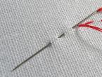
Finished rails, beams and other profiles after rolling are measured in a hot state using the beam splitting method. A laser beam directed at the surface of the profile being measured is reflected and captured by a high-speed, high-resolution sensor. The distance to the profile surface is calculated depending on the position at which the reflected beam is captured by the sensor. Based on the measurement results, the contour of the measured profile can be drawn.
Profile and rail straightening machines
Modern roller-type CRS machines with a compact layout for straightening profiles (Fig. 16, a) are equipped with nine two-support prefabricated leveling rollers with a fixed location. All nine rollers have individual drives. Hydraulic cylinders can adjust the position of the rollers under load or the gap between them. Compared to traditional leveling equipment, such machines have the following advantages:
- uniform and symmetrical application of load, as well as more favorable distribution of residual stresses in profiles;
- compensation of elastic springing of rollers by adjusting their position using hydraulic cylinders;
- hydraulic mechanism for axial installation of each roller;
- assembly of the correct rollers with minimal gaps and maximum accuracy of their installation during the straightening process;
- automated replacement of rollers, taking no more than 20 minutes.

Rice. 16. Leveling machine for steel profiles (a) and rails (b), arranged according to the H-V scheme
Rail straightening machines (Fig. 16, b) consist of horizontal and vertical blocks and are characterized by increased structural rigidity and individual drive of straightening rollers. In combination with off-line rail straightening machines and special tension control systems between straightening rollers, these machines make it possible to achieve a minimum level of residual stress in the rails, which significantly increases their service life.
Distinctive features of rail straightening machines are:
- backlash-free assembly of straight rollers, bushings and supports on adjustable shafts;
- installation of correct bushings on shafts using bayonet rings and high-pressure hydraulic systems;
- automated machine adjustment when changing product sizes;
- Replacing the correct rollers within 30 minutes.
Prospects
The increasing demands made by consumers of long rolled products regarding properties and dimensional accuracy, as well as the need to introduce resource-saving technologies, forced technologists to master the production of finished products directly from rolling heating and without additional heat treatment. In some cases, this provides material properties that cannot be obtained using traditional heat treatment processes.
Advances in modern instrumentation and automation, as well as improvements in the design of rolling mills, have made it possible to achieve a high level of automation in the production process. This has resulted in a number of important achievements, including increased yield, improved product quality and more consistent properties, the ability to respond instantly to process deviations, fine-tuning of rolling equipment, reduced scrap, and reliable documentation of the entire process to ensure guaranteed quality. products.
- P.-Y. Mok
- K. Overhagen
- W. Stelmacher
Over the past years, when improving the technology of long rolling, the main attention has been paid to obtaining the required properties of long products and wire rods directly from rolling heating and the possibility of further processing of rolled products without preliminary heat treatment. In combination with free rolling (to free dimensions), this made it possible to increase the flexibility of the production process. The introduction of continuous casting of beam blanks with dimensions close to those of the finished profile has made significant changes in the process of producing large sections. The number of rolling passes has decreased, rolling mills have reduced their dimensions, the rolling process has been simplified, its economic performance has improved, and energy consumption has been reduced. In addition, when rolling rails and beams, measures such as temperature control and cooling of profiles, and when rolling rails also the possibility of strengthening them in the mill line, led to improved product quality.
- long products,
- small section wire mill,
- large section mill,
- rail and beam mill,
- rolling process,
- finishing,
- heat treatment.
- Burkhardt, M.; Müller, H.; Ellis, G.: Iron Steel Techn. (2004) Nr. 2, S. 50/55.
- Brune, E.; Koller, F.; Kruse, M.; Mauk, P.J.; Plociennik, U.: stahl u. eisen 114 (1994) Nr. 11, S. 87/92.
- Filippini, S.A.; Ammerling, W.J.: Further developments in wire rod and bar production using the 3-roll technology, Proc. AISTech 2008, 5.–8. Mai 2008, Pittsburgh, USA, Vol. 2.
- Hüllen, P. van; Ammerling, J.: Targets, implementation and operating results of the modernization project of a bar mill for engineering steel, Proc. 3. Europ. Rolling Conf., METEC Congress 2003, 16.–20. Juni 2003, Düsseldorf, S. 171/76.
- Alzetta, F.: Iron Steelmak. 29 (2002) Nr. 7, S. 41/49.
- Austen, T.; Ogle, D.; Hogg, J.: EBROS – endless bar rolling system, Proc. AISE Annual Convention and Steel Expo 2002, 30. Sept. – 2. Okt. 2002, Nashville, USA, S. 1/24.
- Knorr, J.S.: BHM – Berg- und Hüttenm. Monatshefte 146 (2001) Nr. 1, S. 2/6.
- Hensel, A.; Lehnert, W.; Krengel, R.: Der Kalibreur (1996) Nr. 57, S. 37/47.
- Mauk, J.: Verfahren zum Walzen schwerer Profile – Vergleich und Bewertung aus umformtechnischer Sicht, Proc. 27. Verformungskundliches Kolloquium, 8.–11. März 2008, Planneralm, Österreich, Montanuniversität Leoben, S. 155/80.
- Engel, G.; Feldmann, H.; Kosak, D.: Der Kalibreur (1987) Nr. 47, S. 3/24.
- Cygler, M.; Engel, G.; Flemming, G.; Meurer, H.; Schulz, U.: MPT – Metallurgical Plant and Technology Intern. 17 (1994) Nr. 5, S. 60/67.
- Pfeiler, H.; Köck, N.; Schroder, J.; Maestrutti, L.: MPT – Metallurgical Plant and Technology Intern. 26 (2003) Nr. 6, S. 40/44.
- Moitzi, H.; Köck, N.; Riedl, A.: Modernste Schienenproduktion – Technologiewechsel an der Schienen walzstraβe, 28. Verformungskundliches Kolloquium, 13. Feb. 2009, Planneralm, Österreich, Montanuniversität Leoben, S. 53/60.
- Lemke, J.; Kosak, T.: Walzen von Profilen aus Beam Blanks, Freiberger Forschungshefte, Reihe B, Bd. 306, 2000, S. 198/214.
Rolling technology includes:
- Preparation of ingots and billets for rolling;
- Determination of the heating mode depending on the chemical composition of the steel and the cross-section of the workpiece;
- Determination of deformation mode (calibration);
- Issues of steel cooling after rolling;
- Operational and final quality control of rolled products.
During the process of casting steel into molds, heating and rolling ingots and billets, surface defects are formed that must be removed. The main surface defects of ingots are films formed as a result of steel splashing during casting and cracks.
Surface defects are removed before (first option) or after (second option) rolling.
Ingots, cooled before being placed in heating wells, are inspected, and any surface defects found are removed.
Defects from the surface of ingots arriving hot for landing in heating wells are not removed before rolling.
Depending on the requirements for the surface quality of the finished product, the first or second option is accepted.
The depth of surface defects on workpieces is 2-3 mm, and the defective layer must be selectively or completely removed.
The following methods for removing surface defects are used:
- Burning of the defective surface layer to a certain depth;
- Gouging, roughing on lathes;
- Cutting with pneumatic chisels and special machines;
- Sanding.
To burn the defective surface layer, autogenous cutters are used for selective removal of defects and fire cleaning machines for complete removal of the defective surface.
As mentioned above, the bulk of the ingots enter the heating wells in a hot state, and, therefore, surface defects cannot be removed before rolling. In this regard, modern crimping rolling mills are equipped with fire cleaning machines for the complete removal of defects in the flow.
After rolling is completed, the workpieces are fed in a hot state into fire cleaning machines, in which a layer of metal 1.5-2.5 mm thick is simultaneously burned from all sides by gas cutting blocks.
Preparation of a wide-band billet before cold rolling involves removing scale formed on the metal surface. Removal of scale from the surface of carbon steel strips is carried out in a solution of sulfuric acid. The active process of scale dissolution occurs at a sulfuric acid content of 26% and a solution temperature of ~ 95°C.
Pickling of hot-rolled broadband steel is carried out in continuous pickling units. Wire rod and section metal intended for further drawing are pickled in special tanks.
Roll calibration
Calibration solves the following problems:
- Establishing the number of passes;
- Establishing the shape and dimensions of the cross-section of the strip after each pass;
- Sequence of alternating stripe shapes.
Rolling produces simple (circle, square, strip, etc.) and complex (rails, beams, angles, etc.) types of rolled products.
Rolling of section and sheet steel is carried out with a greater or lesser number of passes through the rolls.
With each pass through the rolls, the cross-sectional area of the strips is reduced and, if necessary, a rough shape is given to the final product.
Rolling of sheets and broadband steel is carried out on a smooth roll barrel. The profile of the forming barrel is determined by calibrating the sheet rolls.
During hot rolling, the roll barrel is made concave, and during cold rolling, it is convex. Concavity compensates for the thermal expansion of the roll barrel, convexity compensates for the deflection of the roll due to the rolling force.
To obtain the required shape of rolled products, ring grooves of various shapes are cut on the barrel of rolls of section rolling mills on roll lathes.
A circular groove on one roll is called a groove. The streams of two rolls form a caliber.
The shape of the gauges used to produce rolled products of simple shape - square, circle, is shown in Fig. 1 (c, f, g).
Oval gauges are used in combination with square and round gauges (Fig. 1, 6, c, etc.), rhombic gauges - in combination with square gauges (Fig. 1, e).
Rectangular (box) gauges (I, II) are used for drawing metal on blooming mills, continuous billet mills and roughing stands of section mills.
 Rice. 1. Scheme of calibration of rolls of small-section mill 250
Depending on the purpose, there are four groups of calibers:
- Exhaust, used to reduce the cross-sectional area;
- Preparatory, they further reduce the cross-sectional area and give the strip the rough shape of the finished product;
- Pre-finishing, they further reduce the cross-sectional area and prepare to obtain the final shape of the rolled product;
- Finishing, gives the strip its final shape.
Rolling of sections and sheet steel is carried out in several passes through rolls. The distribution of reductions among passes is made taking into account the force on the rolls, the power of the main electric motor, the strength of the working stand parts, the conditions for gripping the metal by the rolls, and the plasticity of the metal.
When rolling cast metal, the reduction in the first passes is assumed to be small, since the ductility of the metal is low due to its coarse-grained structure. Taking into account the above factors, the minimum possible number of passes is achieved. In Fig. 1 schematically shows the calibration of the rolls of the small-section mill 250.
Depending on the cross-sectional area of the finished rolled product, a square billet receives compression in all 12 stands (Fig. 1, b, f), or only in eight stands when rolling a billet with a diameter of 18-19 mm (X, c). Box gauges are cut on the rolls of the first two stands. On the rolls of working stands III, IV, V, VI, grooves of gauges of the oval-square system are cut.
On the rollers of the pre-finishing and finishing working stands, strands of calibers are cut, intended for the preparation and production of round, square and angular profiles.
Process control

In the process of metallurgical production, melting control, control of production processes, as well as finished products are carried out. Melting control establishes the compliance of the ingots of a given melt with the technical conditions: the quality of the steel is determined, the conformity of the quality of the steel for the rolling of certain products. Based on the results of melt control, a technology for rolling ingots of a given melt is assigned.
Control of production processes is carried out in the following areas:
- Storage of ingots, billets;
- Heating before rolling;
- Rolling of ingots into blanks and blanks into finished products;
- Cutting, straightening of blanks and finished products;
- Cooling after hot rolling and heat treatment;
- Finishing, marking and delivery of finished products.
Control of production processes is carried out on the basis of technological instructions for each site.
Control of finished products establishes compliance of finished rolled products with GOST requirements or technical specifications: for physical and mechanical properties, for internal and surface defects, for dimensions and straightness (flatness) of rolled products, etc.
Technological schemes of rolling production at a metallurgical plant
Depending on the source material, metallurgical plants use two schemes for the production of rolled products (Fig. 2). When using ingots 1 as the starting material, the technological scheme provides for a section of heating wells and a crimping mill - blooming or slab 2, 3.
 Rice. 2. Scheme of rolled products production
When using blooms or slabs as the starting material, the technological process begins with billet mills - a continuous billet mill 4 for section rolling or a wide-band hot rolling mill 5 for sheet rolling.
Subsequent technological operations for obtaining rolled products are the same for both schemes. In the production of long products, the billet is supplied to large-section and medium-section 9 mills, small-section, wire 6 and strip 7 mills. Directly from the blooms, rolling is carried out on rail-beam and large-section mills 8. In sheet production, the billet is supplied to single- and multi-stand cold rolling mills 10. In plate mills, ingots and slabs are used as the starting material.
Bloom production
A bloom is a square blank with rounded corners with a cross-section of up to 400×400 mm.
Depending on the range of blooms and the required productivity, single-stand, two-roll reversible and multi-stand blooming machines are used.
 Rice. 3. Layout of blooming equipment 1300
Single-cage blooming plants are most widespread.
A modern crimping machine is a powerful automated single-stand blooming machine with a roll diameter of 1300-1500 mm. In Fig. Figure 3 shows a diagram of the arrangement of blooming equipment 1300. Ingots from the steelmaking shop are fed into the span of heating wells 1 on platforms along railway tracks. Ingots weighing 10-15 tons, heated to rolling temperature, are removed from the heating wells by an overhead crane with a tong gripper and transferred to the platform of the ingot carrier 2. Four ingot carriers, continuously moving along a circular path, alternately approach the receiving roller conveyor 3 of the blooming. The next ingot carrier automatically stops parallel to the receiving roller table, and the ingot is loaded onto the roller table rollers using a stationary rack-type pusher. Feeding and rolling roller conveyors 4 transport the ingot to the blooming working stand. A rotary table is installed in the line of the supply roller table - a scale, with which the ingot is automatically weighed and, if necessary, rotated in a horizontal plane by 180°. The rollers of the working roller conveyor bring the ingot to the rolls of the working stand 5.
 Rice. 4. Calibration of blooming rollers
The working cage of the Blooming 1300 consists of two massive steel frames weighing 105 tons each. Rolls with a diameter of 1300 mm and a barrel length of 2800 mm, made by forging from chromium-nickel steel, are mounted in the frame assembly on textolite bearings. Setting the gap between the rolls is ensured by a screw pressure mechanism with an electromechanical drive; balancing of the upper roll with the cushions is carried out by a lever-load mechanism. Each roller is driven by a DC electric motor MP-110-65 with a power of 6800 kW, 0-60-90 rpm through universal spindles with sliding liners.
In Fig. Figure 4 shows the calibration of blooming rollers. The ingot is rolled in the first wide caliber. As the cross-section decreases, the roll is transferred to box gauges II, III, IV (see Fig. 4). If a small number of slabs are rolled on a blooming machine, then the first gauge is made in the middle of the roll to evenly distribute the rolling force on the left and right bearings. The specified width (up to 1000 mm) is ensured by passing the slab onto the edge through box gauges. In 9-13 passes through the rolls, the ingots are rolled into blooms with a cross-section of 300×300–370×370 mm.
The turning of the rolls in front of the odd gaps and their installation along the length of the roll barrel against the required caliber is ensured by a hook tilter built into the manipulator ruler and by manipulators installed on both sides of the working stand. The scale formed on the surface of the ingot during the heating process is destroyed during the first passes through the rolls with slight compression and is washed off with water. Under the working cage there is a channel through which scale is transported by a stream of water into settling pit 6 (see Fig. 3). The rolled blooms arrive at the fire stripping machine 7, installed after the working stand, and are transferred to the shearing section 8 by a transport roller conveyor.
Using scissors, the front and rear ends of the bloom are trimmed to remove shrinkage cavities and defective end sections, as well as the bloom is cut into measured lengths. The trim when rolling carbon boiling steel is 3-5%, when rolling calm steel - up to 17.5% of the ingot weight. The cut parts of the blooms end up on a conveyor, which is used to load railway platforms.
To avoid misgrading, blooms and trimmings are branded. The cleaned and trimmed blooms are supplied along roller conveyor 9 for further rolling to a continuous billet mill. On the 1300 blooming machine it is possible to roll slabs with a thickness of 100-200 mm and a width of up to 1000 mm. The annual productivity of automated blooming 1300 is 5.5-6 million tons of ingots. In specialized sheet production, a slab with a roll diameter of 1150–1250 mm is installed as a crimping mill. The slab working stand has vertical rollers that provide width compression. At the slab mill, ingots weighing up to 30 tons are rolled into slabs with a thickness of 150-300 mm and a width of 1000-1550 mm. The slab production capacity is 6.5 million tons of ingots per year.
Production of blanks
Billet mills are designed for rolling blooms into billets for section, wire and pipe rolling mills. Depending on the specialization, billet mills roll from blooms with a cross-section of ZOOx300-370×370 mm: large billets with a square cross-section from 125×125 to 140×140 mm and blooms with a cross-section of 200×200 mm; high-quality square billets with a cross-section from 80×80 to 120×120 mm; round billets with a diameter of 75-300 mm for pipe rolling mills.
In Fig. Figure 5 shows a diagram of the arrangement of equipment for a continuous billet mill (NCM) 900/700/500.
Blooms without heating are supplied to the NZS via roller conveyor 1. The NZS consists of three groups of working stands.
 Rice. 5. Layout of equipment NZS 900/700/500
The nominal diameter of the rolls for groups of working stands is: I - 900 mm, II - 700 mm and III - 500 mm. Rotators 2 and 6 are installed in front of groups II and III of working stands. In the line of outgoing roller table 3, shears with a force of 8 MN are installed for cutting workpieces with a cross-section of 120×120 mm. After the third group of working stands, workpieces with a cross-section of 60×60–80×80 mm are supplied to refrigerator 5. As follows from the considered technological process diagram for rolling a workpiece at NZS 900/700/500, in each group of working stands, rolling is carried out according to the principle of a continuous process, and Therefore, it is necessary to achieve constant second volumes of metal in groups of stands.
When calibrating NZS rolls, the calibration constant is determined: C=FD p n(1+S h), where F is the cross-sectional area of the rolled strip; D p is the working diameter of the rolls; n is the number of roll rotations; S h - metal advances the rolls.
Rolling in continuous groups of working stands without support or high tension is possible only if the constant calibration of all stands in each group of NZS is equal. The distance between groups of working stands is assumed to be slightly greater than the length of the roll coming out of the last stand of the previous group of NZS, and it is not necessary to achieve constancy between groups of stands.
Constant calibration is regulated by changing the number of rotations of the rolls. Flexible adjustment of the roll rotation speed is ensured by an individual drive for each working stand. Behind the last stand of the NZS, flying shears 4 are installed, with which the workpieces are cut into measured lengths of 8-12 m.
The exit speed of workpieces from the third group of NZS is 5-7 m/s. The cut workpieces are collected into bundles on a baling roller table and transferred to the mill's refrigerators.
After cooling, the workpieces are inspected and surface defects are removed.
The annual productivity of the NZS 900/700/500 is ~ 5 million tons.

On section rolling mills, profiles with a round section with a diameter of up to 220 mm, a square section with a square side from 8 to 220 mm, a rectangular section with a height of 4 to 60 mm and a width of 12 to 350 mm, equal and unequal angles with a flange width from 16 to 350 mm are produced. 250 mm, beams and channels up to 300 mm high, wire rod with a diameter of 5-9 mm. Channels and beams with a height of up to 600 mm are rolled on rail-beam mills and on special beam rolling mills with a height of up to 1000 mm and a flange width of up to 420 mm.
The initial workpieces for rolling are ingots: steel weighing up to 60 tons, non-ferrous metals and their alloys usually weighing up to 10 tons. In the production of sectional profiles, a steel ingot weighing up to 15 tons is hot rolled on a blooming machine, producing square (or close to it) billets ) sections (from 140X140 to 450x450 mm), called blooms. Then the blooms are supplied to billet mills for rolling billets of the required sizes or directly to large-section mills for rolling large profiles of long steel. On billet and section mills, the billet passes sequentially through a series of gauges.
The development of a system of sequential gauges necessary to obtain a particular profile is called calibration. Calibration is a complex and demanding process. Incorrect calibration can lead not only to reduced productivity, but also to defective products. The greater the difference in cross-sectional dimensions of the initial workpiece and the final product and the more complex the profile of the latter, the greater the number of gauges required to obtain it. The number of calibers may vary; for example, when rolling wire with a diameter of 6.5 mm, their number reaches 21. After rolling, the strips are cut into measured lengths, cooled, straightened in a cold state, heat treated, and surface defects are removed.
In the production of rolled sheets, a steel ingot weighing up to 50 tons is hot rolled on a slab or blooming machine, producing a rectangular cross-section blank (maximum thickness - 350 and width - 2300 mm), called a slab.
Currently, instead of rolled billets, billets in the form of slabs obtained by continuous casting are widely used. Slabs are rolled mostly on continuous hot rolling mills, consisting of two groups of working stands - roughing and finishing, located one behind the other. Before each group of stands, scale is knocked off in descaling machines. After rolling, the strip with a thickness of 1.2-16 mm is wound into a roll. Finishing operations for the production of hot-rolled sheets include cutting, pickling, heat treatment, etc.
The starting material for cold rolling of sheets less than 1.5 mm thick is usually hot-rolled coils. Modern cold rolling mills produce sheet steel with a minimum thickness of 0.15 mm and strips with a minimum thickness of 0.0015 mm. The modern method of cold rolling is coil rolling. The pre-hot-rolled sheet is cleaned by pickling in acids followed by washing. They are rolled on single-stand and multi-stand continuous four-roll mills, as well as on multi-roll mills. After cold rolling, the material undergoes finishing operations: annealing in protective gases, applying coatings if necessary, cutting into dimensional sheets, etc.
When rolling seamless pipes, the first operation is piercing - the formation of a hole in an ingot or round billet. This operation is performed hot on piercing mills. The most widely used are piercing mills with two barrel-shaped rolls, the axes of which are located at a slight angle (5-15°) to each other. Both rolls rotate in the same direction, i.e. in this case the principle of cross-helical rolling is used. Thanks to this arrangement of the rolls, the workpiece receives simultaneous rotational and translational motion. In this case, radial tensile stresses arise in the metal, which cause the metal to flow from the center in the radial direction, forming an internal cavity, and facilitate the piercing of the hole with a mandrel installed in the path of movement of the workpiece.
Subsequent rolling of the stitched billet into a pipe of the required diameter and wall thickness is carried out on rolling mills. For example, in the most common method, the pipe is rolled on a short mandrel in a so-called automatic twin-roll mill. The rolls form sequentially arranged round gauges; the gap between the mandrel mounted on a long rod and the roll grooves determines the thickness of the pipe wall. To eliminate uneven cross-sectional wall thickness and scratches after rolling, pipes are rolled in rolling mills, the working stand of which is similar in design to the stand of a piercing mill. Then, to obtain a given diameter, the pipes are rolled in a calibrating multi-stand longitudinal rolling mill without a mandrel; and if it is necessary to produce pipes with a diameter of less than 80 mm, also in continuous reduction mills with working stands of a similar design.
Welded pipes are made from a flat piece - a strip (called strip) or from sheets, the width of which corresponds to the length (or half the length) of the pipe circumference. The process of manufacturing a welded pipe includes the following main operations: molding a flat blank into a pipe, welding the edges, reducing (reducing) the diameter of the resulting pipe. The following methods are most often used for welding: furnace welding, resistance welding and submerged arc welding. When producing pipes by furnace welding, a strip unwound from a roll is straightened, heated in a narrow long (up to 40 m) gas furnace to a temperature of 1300-1350 ° C and formed into a pipe in a continuous rolling mill (Fig. 3.12). The mill consists of 6-12 working stands, in which the rolls form round grooves. When rolling in calibers, the edges pressed against one another, additionally heated to a high temperature by blowing oxygen, are welded. The pipe leaving the mill is cut with a special saw into pieces of the required length and then calibrated on a calibration mill. This method produces pipes of the lowest cost from low-carbon steel (St2kp) with a diameter of 10-114 mm.
Electric welding can be used to produce pipes of large diameter (up to 2500 mm) with a thin wall (up to 0.5 mm) from alloy steels.
In the production of pipes by resistance welding, tapes or strips are cold rolled into a pipe in continuous forming mills. When leaving the forming mill, the pipe blank enters the pipe electric welding mill, where the edges of the pipe are pressed against each other by two pairs of vertical rolls and simultaneously welded with roller electrodes. After welding, the pipe is calibrated and cut into pieces.
Submerged arc welding is used to produce pipes with straight and spiral seams. In the first case, the prepared sheet is formed on sheet-bending roller mills or on presses, then welded, and the seams are placed on the outside and inside of the pipe. When producing pipes with a spiral seam, the tape, unwound from a roll, is rolled in a spiral into a pipe and then welded along the edges.
Pipes with a thinner wall, high surface quality and dimensional accuracy are produced in cold rolling mills of various types of pipes, as well as by drawing. In this case, hot-rolled pipes are used as a workpiece.
The processes for obtaining special types of rolled products are very diverse. Moreover, some of them are carried out at metallurgical enterprises, and others at machine-building enterprises. Of particular importance is the rolling of periodic profiles, which are used as a shaped blank for subsequent stamping and as a blank for final machining. Periodic profiles are mainly produced by transverse and helical rolling. On helical rolling machines, not only periodic profiles are produced, but also blanks of balls and spherical rollers for rolling bearings (Fig. 3). Rollers 2 and 4 rotate in the same direction. The roll streams of the appropriate shape are made along a helical line. The workpiece 1 receives rotational and translational motion during rolling; it is protected from flying out of the rolls by centering stops 3. Production of other special types of rolled products, most often carried out at machine-building enterprises.
Rice. 3. Scheme of rolling balls in a helical rolling mill
5.2 Mechanical shop
One of the main tasks of mechanical engineering is the further development, improvement and development of new technological methods for processing blanks of machine parts, the use of new structural materials and improving the quality of processing parts. Particular attention is paid to finishing and finishing technological methods of processing, the volume of which in the total labor intensity of processing parts is constantly increasing. Along with mechanical cutting processing, plastic deformation processing methods using chemical, electrical, light, radiation and other types of energy are used. Combined processing methods are very progressive.
Metal cutting is the process of cutting off a layer of metal in the form of chips from the surface of a workpiece with a cutting tool to obtain the required geometric shape, dimensional accuracy, relative position and roughness of the surfaces of the part. To cut a layer of metal from a workpiece, it is necessary to impart relative movements to the cutting tool and the workpiece. The tool and the workpiece are installed and secured in the working parts of the machines that provide these relative movements: in the spindle, on the table, in the turret. The movements of the working parts of the mills are divided into cutting, installation and auxiliary movements. Movements that cut off a layer of metal from a workpiece or cause a change in the state of the machined surface of the workpiece are called cutting movements. These include the main movement and the feed movement.
The main thing is taken to be the movement that determines the rate of deformation and separation of the chips, and the feed movement is the movement that ensures the cutting edge of the tool penetrates the workpiece material. These movements can be continuous or intermittent, and are rotational, translational, or reciprocating in nature. The speed of the main movement is denoted by v, the feed amount -s.
The movements that ensure the relative position of the tool and the workpiece for cutting a certain layer of material from it are called installation movements. Auxiliary movements include transporting the workpiece, securing workpieces and tools, rapid movements of the working parts of the machine, etc.
Cutting tools in this industry operate under conditions of high power loads, high temperatures and friction. Therefore, tool materials must satisfy a number of special operational requirements. The material of the working part of the tool must have great hardness and high permissible stresses for bending, tension, compression, and torsion. The hardness of the material of the working part of the tool must significantly exceed the hardness of the workpiece material.
High strength properties are necessary for the tool to have resistance to the corresponding deformations during the cutting process, and sufficient viscosity of the tool material to withstand the dynamic impact load that occurs when processing workpieces made of brittle materials and workpieces with an intermittent surface. Tool materials must have high red resistance, i.e., maintain greater hardness at high heating temperatures. The most important characteristic of the material of the working part of the tool is wear resistance. The higher the wear resistance, the slower the tool wears out. This means that the variation in the sizes of parts sequentially processed with the same tool will be minimal.
The classification of metal-cutting machines adopted in our country is based on the technological method of processing workpieces. Classification by technological processing method is carried out in accordance with such characteristics as the type of cutting tool, the nature of the processed surfaces and the processing scheme. Machine tools are divided into lathes, drilling, grinding, polishing and finishing, gear-processing, milling, planing, cutting, broaching, thread-processing, etc.
Classification according to a set of characteristics is most fully reflected in the national Unified System of Symbols for Machine Tools. It is built according to the decimal system; All metal-cutting machines are divided into ten groups, the group into ten types, and the type into ten standard sizes. The group includes machines based on the common technological method of processing or those similar in purpose (for example, drilling and boring). Types of machine tools are characterized by such features as purpose, degree of versatility, number of main working parts, and design features. Within the type, machines are distinguished by technical characteristics.
In accordance with this classification, each machine is assigned a specific code. The first digit of the code determines the group of machines, the second type, the third (sometimes the third and fourth) shows the conditional size of the machine. The letter in second or third place allows you to distinguish between machines of the same standard size, but with different technical characteristics. The letter at the end of the code indicates various modifications of machines of the same basic model. For example, the code 2N135 designates a vertical drilling machine (group 2, type 1), modernized (N), with the largest nominal drilling diameter of 35 mm (35).
There are universal, general purpose, specialized and special machines. A wide variety of work is performed on universal machines, using many types of workpieces. Examples of such machines can be screw-cutting lathes, horizontal milling cantilever machines, etc. General-purpose machines are designed to perform certain work on workpieces of many types (multi-tool, cutting-off lathes). Specialized machines are designed for processing workpieces of the same name, but of different sizes (for example, machines for processing crankshafts). Special machines perform a certain type of work on one specific workpiece.
6. PROCESS SAFETY
Reduction of industrial hazards is carried out by following the appropriate instructions:
No. 013- For those working on lathes, automatic and semi-automatic machines with CNC (2000).
No. 029- For those working on metal-cutting machines (2002).
6.1 General safety requirements
Only those workers who have studied their structure and operating instructions may be allowed to service the mechanisms. Before turning it on, you should make sure that the mechanism is in working order and that starting it does not endanger anyone. If, during the inspection, any malfunctions are discovered in the mechanism or its safety devices, the worker must inform the foreman about this and not begin work until they are eliminated.
Do not leave the operating mechanism unattended. Even if you are absent from the workplace for a short time, you should stop the mechanism and inform the foreman about your departure. Do not touch the moving parts of the mechanism or lean on it; take or pass objects through a working mechanism; clean, lubricate, repair the mechanism on the go. It is unacceptable to use gloves and mittens when performing work if there is a risk of getting caught by rotating parts. If any object gets into the mechanism during operation, it is prohibited to remove it without turning off the mechanism. It is necessary to stop the mechanism and slowly, by rotating it by hand, release the object caught in it.
It is not allowed to allow persons unrelated to the work being performed into your workplace, or to entrust the operating mechanism to another worker.
6.2 Installation and dismantling of equipment.
Machine tools, presses and other equipment must be installed on solid foundations or foundations, carefully aligned and securely fastened. The design of equipment (machine, press, etc.) and its individual parts must include special frames, bolts, windows, brackets and other devices for quick, convenient and reliable slinging and safe movement during loading, dismantling and repair of equipment.
Slinging devices must be located taking into account the center of gravity of the load being carried and must not be damaged by tensioned chains or cables during lifting. Eye bolts, bosses, brackets, walls, in which there are windows for slinging, must be designed for strength, taking into account the mass of the load being lifted and the overload that occurs during transportation.
During installation, dismantling and repair of equipment; its components and assemblies with a height of more than 1.5 m from the floor or working platform are provided with strong and stable scaffolding, scaffolding, etc. for safe work at height. Workplaces for repair mechanics must be equipped with cabinets, workbenches, and shelving.
Before repairs, the equipment is disconnected from the power supply, and a poster with the inscription “Do not turn on - people are working” is hung on the starting devices.
7. TECHNICAL AND ECONOMIC INDICATORS OF PART MANUFACTURE
A feasibility study for the selection of a workpiece for a workpiece is carried out in several areas of metal intensity, labor intensity and cost, taking into account specific production conditions. A feasibility study is carried out on two or more selected options. In an economic assessment, the metal intensity, cost or labor intensity of each option for manufacturing a workpiece is determined, and then they are compared.
The technical and economic calculation of the manufacture of the workpiece is carried out in the following order:
1. Establish a method for obtaining a workpiece according to the type of production, part design, material and other technical requirements for the manufacture of the part.
2. Allowances are assigned to the machined surfaces of the part according to the selected method of obtaining the workpiece according to standard tables or calculations are made using the analytical method;
3. Determine the design dimensions for each surface of the workpiece;
4. Assign maximum deviations for the dimensions of the workpiece according to standard tables, depending on the production method;
Technical and economic indicators of part manufacturing.
Material:
· Size: M20
· Steel grade: St25
· Workpiece weight of one piece = 0.313 kg
· Price for 1 kg = 23-00 (rub.)
· Cost per unit = 7-20 (rub.)
1.3 The worker’s wage per unit of production is 5-72 (rub.).
2. The additional wage of a worker per unit of production is 1-43 (rub.).
3. Social insurance contributions are 1-99 (rub.).
4. Special expenses are 1-14 (rub.).
5. Shop costs are 17-16 (rub.)
6. Factory overhead costs are 11-44 (rub.)
7. The final factory cost of the part is 46-08 (rub.)
CONCLUSION
The main goal of technological process design is to reduce product costs and increase labor productivity. The solution to this problem must be carried out in accordance with the given type of production. The design of a new technological process should include analysis of initial data (determining the service purpose of the product, analysis of technical conditions and manufacturability of structures), determination of the class and group of parts, quantitative assessment of product groups, selection of the initial workpiece and method of its manufacture, selection of technological bases, drawing up a technological processing routes, development of technological operations.
The technological process for this part (screw) is compiled in the most rational way. The shape of the part is simple enough for processing to perform its functions; the part in question is obtained rationally from an economic point of view.
The final factory cost of the screw is not high.
Allowances are determined by calculation and analytical method, which allows for metal savings, reduction of processing labor intensity and reduction of production costs.
Optimal cutting modes have been selected, which ensures the highest labor productivity at the lowest cost of operation with the required quality of processing.
LIST OF REFERENCES USED
1. Course design on the subject “Mechanical Engineering Technology”, Dobrydnev I.S., M.: Mechanical Engineering 1985.
2. Technology of structural materials, Dalsky A.M., M.: Mechanical Engineering 1985.
3. Occupational safety in mechanical engineering, Mazov V.A. M.: Mechanical Engineering 1983.