DIY Tesla transformer, the simplest circuit. Marking Tesla lamps Components and assembly of the Tesla transformer circuit
In 1891, Nikola Tesla developed a transformer (coil) with which he experimented with high voltage electrical discharges. The device developed by Tesla consisted of a power supply, a capacitor, primary and secondary coils installed so that voltage peaks alternate between them, and two electrodes separated from each other by a distance. The device was named after its inventor.
The principles Tesla discovered with this device are now being used in applications ranging from particle accelerators to televisions and toys.
Tesla transformer can be made by hand. This article is devoted to this issue.
First you need to decide on the size of the transformer. It is possible to build a large appliance if the budget allows. It should be remembered that this device generates high voltage discharges (create micro lightning) that heat and expand the surrounding air (create micro thunder). The generated electric fields can damage other electrical devices. Therefore, it is not worth building and running a Tesla transformer at home; it is safer to do this in remote locations, such as a garage or shed.
The size of the transformer will depend on the distance between the electrodes (on the size of the resulting spark), which in turn will depend on the power consumption.
Components and Assembly of the Tesla Transformer Circuit
- We need a transformer or generator with a voltage of 5-15 kV and a current of 30-100 milliamps. The experiment will fail if these parameters are not met.
- The current source must be connected to the capacitor. The capacitor capacitance parameter is important, i.e. the ability to hold an electric charge. The unit of capacitance is farad - F. It is defined as 1 ampere-second (or coulomb) per 1 volt. As a rule, capacitance is measured in small units - μF (one millionth of a farad) or pF (one trillionth of a farad). For a voltage of 5 kV, the capacitor must have a rating of 2200 pF.
- The capacitor(s) is connected to a spark plug - an air gap between the contacts of which an electrical breakdown occurs. In order for the contacts to withstand the heat generated by the spark during the discharge, their required diameter must be 6 mm. minimum. A sparkler is necessary to excite resonant oscillations in the circuit.
- primary coil. It is made from a thick copper wire or tube with a diameter of 2.5-6 mm., Which is twisted into a spiral in one plane in the amount of 4-6 turns
- The primary coil is connected to the arrester. The capacitor and primary coil must form a primary circuit that is in resonance with the secondary coil.
- The primary coil must be well insulated from the secondary.
- secondary coil. It is made of thin enameled copper wire (up to 0.6 mm). The wire is wound on a polymer tube with an empty core. The height of the tube should be 5-6 of its diameters. 1000 turns should be carefully wound onto the tube. The secondary coil may be placed inside the primary coil.
- The secondary coil at one end must be grounded separately from other devices. Grounding directly "to the ground" is best. The second wire of the secondary coil is connected to the torus (lightning emitter).
- Thor can be made from an ordinary ventilation corrugation. It is located above the secondary coil.
- The secondary coil and the torus form a secondary circuit.
- We turn on the supply generator (transformer). Tesla transformer is working.
It is even better to connect several capacitors in series. In this case, each capacitor will retain part of the charge, the total retained charge will increase by a multiple.
Excellent video explaining the principles of the Tesla transformer
Precautionary measures
Be careful: the voltage accumulated in the Tesla transformer is very high and leads to guaranteed death in case of breakdowns. The current strength is also very large, far exceeding the value that is safe for life.
There is no practical application of the Tesla transformer. This is an experimental setup that confirms our knowledge of the physics of electricity.
From an aesthetic point of view, the effects that the Tesla transformer generates are amazing and beautiful. They largely depend on how correctly it is assembled, whether the current is sufficient, whether the circuits resonate correctly. Effects can include a glow or discharges generated on the second coil, or full-fledged lightning piercing the air from the torus. The resulting glows are shifted to the ultraviolet range of the spectrum.
A high-frequency field is formed around the Tesla transformer. Therefore, for example, when an energy-saving light bulb is placed in this field, it starts to glow. This same field leads to the formation of large amounts of ozone.
The Tesla transformer (we will discuss the principle of operation of the apparatus later) was patented in 1896, on September 22. The device was presented as a device that produces electric currents of high potential and frequency. The device was invented by Nikola Tesla and named after him. Let's take a closer look at this device.
Tesla transformer: principle of operation
The essence of the operation of the device can be explained by the example of a well-known swing. When they are swinging under forced conditions, which will be maximum, it will become proportional to the applied force. When swinging in free mode, the maximum amplitude will increase many times over with the same efforts. This is the essence of the Tesla transformer. An oscillatory secondary circuit is used as a swing in the apparatus. The generator plays the role of the applied effort. With their consistency (pushing at strictly necessary periods of time), a master oscillator or a primary circuit (in accordance with the device) is provided.
Description
A simple Tesla transformer includes two coils. One is primary, the other is secondary. Tesla also consists of a toroid (not always used), a capacitor, a spark gap. The last - the interrupter - is found in the English version of Spark Gap. The Tesla transformer also contains an "output" terminal.

Coils
The primary contains, as a rule, a large-diameter wire or a copper tube with several turns. The secondary coil has a smaller cable. Its turns are about 1000. The primary coil can have a flat (horizontal), conical or cylindrical (vertical) shape. Here, unlike a conventional transformer, there is no ferromagnetic core. Due to this, the mutual inductance between the coils is significantly reduced. Together with the capacitor, the primary element forms an oscillatory circuit. It includes a spark gap - a non-linear element.
The secondary coil also forms an oscillatory circuit. The toroidal and its own coil (interturn) capacitances act as a capacitor. The secondary winding is often covered with a layer of varnish or epoxy. This is done to avoid electrical breakdown.
Discharger
The Tesla transformer circuit includes two massive electrodes. These elements must be resistant to flow through high currents. Be sure to have an adjustable gap and good cooling.
Terminal
In a resonant Tesla transformer, this element can be installed in different versions. The terminal may be a sphere, a sharpened pin, or a disc. It is intended to produce predictable spark discharges with a large length. Thus, two coupled oscillatory circuits form a Tesla transformer.
Energy from the ether is one of the goals of the apparatus functioning. The inventor of the device sought to achieve a wave number Z of 377 ohms. He made coils of ever larger sizes. Normal (full) operation of the Tesla transformer is ensured when both circuits are tuned to the same frequency. As a rule, in the process of adjustment, the primary is adjusted to the secondary. This is achieved by changing the capacitance of the capacitor. The number of turns at the primary winding also changes until the maximum voltage appears at the output.
In the future, it is planned to create a simple Tesla transformer. The energy from the ether will work for humanity to the fullest extent.

Action
The Tesla transformer operates in a pulsed mode. The first phase is a capacitor charge up to the breakdown voltage of the discharge element. The second is the generation of high-frequency oscillations in the primary circuit. A spark gap connected in parallel closes the transformer (power source), excluding it from the circuit. Otherwise, he will make certain losses. This, in turn, will reduce the quality factor of the primary circuit. As practice shows, such an influence significantly reduces the length of the discharge. In this regard, in a well-built circuit, the arrester is always placed parallel to the source.
Charge
It is produced by an external source based on a low-frequency step-up transformer. The capacitor capacitance is chosen so that it forms a certain circuit together with the inductor. The frequency of its resonance should be equal to the high-voltage circuit.
In practice, things are somewhat different. When the calculation of the Tesla transformer is carried out, the energy that will be used to pump the second circuit is not taken into account. The charge voltage is limited by the voltage at the breakdown of the arrester. It (if the element is air) can be adjusted. The breakdown voltage is corrected by changing the shape or the distance between the electrodes. As a rule, the indicator is in the range of 2-20 kV. The sign of the voltage should not "short" the capacitor too much, on which there is a constant sign change.

Generation
After the breakdown voltage between the electrodes is reached, an electrical avalanche-like breakdown of the gas is formed in the spark gap. The capacitor discharges onto the coil. After that, the breakdown voltage decreases sharply due to the remaining ions in the gas (charge carriers). As a result, the circuit of the oscillation circuit, consisting of a capacitor and a primary coil, remains closed through the spark gap. It generates high frequency vibrations. They gradually fade, mainly due to losses in the arrester, as well as the escape of electromagnetic energy to the secondary coil. Nevertheless, the oscillations continue until the current creates a sufficient number of charge carriers to maintain a significantly lower breakdown voltage in the spark gap than the amplitude of oscillations of the LC circuit. There is a resonance. This results in high voltage at the terminal.
Modifications
Whatever type of Tesla transformer circuit, the secondary and primary circuits remain the same. However, one of the components of the main element may be of a different design. In particular, we are talking about fluctuations. For example, in the SGTC modification, this element is performed on the spark gap.

RSG
The high power Tesla transformer includes a more complex spark gap design. In particular, this applies to the RSG model. The abbreviation stands for Rotary Spark Gap. It can be translated as follows: rotating / rotary spark or static gap with arc quenching (additional) devices. In this case, the frequency of operation of the gap is selected synchronously with the frequency of capacitor charging. The design of the spark rotor gap includes a motor (usually it is electric), a disk (rotating) with electrodes. The latter either close or approach the mating components to close.
In some cases, a conventional spark gap is replaced by a multi-stage one. For cooling, this component is sometimes placed in gaseous or liquid dielectrics (in oil, for example). As a typical technique for extinguishing the arc of a statistical spark gap, purge of the electrodes using a powerful air jet is used. In some cases, the Tesla transformer of classical design is supplemented with a second arrester. The task of this element is to protect the low-voltage (feeding) zone from high-voltage surges.

lamp coil
In the VTTC modification, vacuum tubes are used. They play the role of an RF oscillation generator. As a rule, these are quite powerful lamps of the GU-81 type. But sometimes you can find low-power designs. One of the features in this case is the absence of the need to provide high voltage. To get relatively small discharges, you need about 300-600 V. In addition, VTTC makes almost no noise, which appears when the Tesla transformer operates on the spark gap. With the development of electronics, it became possible to significantly simplify and reduce the size of the device. Instead of a design on lamps, a Tesla transformer on transistors began to be used. Usually a bipolar element of appropriate power and current is used.
How to make a Tesla transformer?
As mentioned above, a bipolar element is used to simplify the design. Undoubtedly, it is much better to use a field effect transistor. But bipolar is easier to work with for those who are not experienced enough in assembling generators. The winding of the communication coils and the collector is carried out with a wire of 0.5-0.8 millimeters. On a high-voltage part, the wire is taken 0.15-0.3 mm thick. Approximately 1000 turns are made. A spiral is placed at the "hot" end of the winding. Power can be taken from a transformer of 10 V, 1 A. When using power from 24 V or more, the length increases significantly. For the generator, you can use the KT805IM transistor.
Application of the device
At the output, you can get a voltage of several million volts. It is capable of creating impressive discharges in the air. The latter, in turn, can have a length of many meters. These phenomena are very attractive outwardly for many people. Fans of the Tesla transformer are used for decorative purposes.
The inventor himself used the apparatus for the propagation and generation of oscillations, which are aimed at wireless control of devices at a distance (radio control), data and energy transmission. At the beginning of the twentieth century, the Tesla coil began to be used in medicine. Patients were treated with high-frequency weak currents. They, flowing through a thin surface layer of the skin, did not harm the internal organs. At the same time, the currents had a healing and tonic effect on the body. In addition, the transformer is used to ignite gas discharge lamps and to search for leaks in vacuum systems. However, in our time, the main application of the apparatus should be considered cognitive and aesthetic.
effects
They are associated with the formation of various kinds of gas discharges during the operation of the device. Many people collect Tesla transformers in order to be able to watch the spectacular effects. In total, the device produces discharges of four types. It is often possible to observe how the discharges not only depart from the coil, but are also directed from grounded objects in its direction. They can also have corona glows. It is noteworthy that some chemical compounds (ionic) when applied to the terminal may change the color of the discharge. For example, sodium ions make spark orange, while boron ions make spark green.

streamers
These are dimly luminous branched thin channels. They contain ionized gas atoms and free electrons split off from them. These discharges flow from the terminal of the coil or from the sharpest parts directly into the air. At its core, the streamer can be considered visible air ionization (glow of ions), which is created by the HV field at the transformer.
arc discharge
It occurs quite frequently. For example, if the transformer has sufficient power, an arc may be formed when a grounded object is brought to the terminal. In some cases, it is required to touch the object to the exit, and then retract to an increasing distance and stretch the arc. With insufficient reliability and power of the coil, such a discharge can damage the components.
spark
This spark charge is discharged from sharp parts or from the terminal directly to the ground (grounded object). Spark is presented in the form of rapidly changing or disappearing bright filiform stripes, branched strongly and often. There is also a special type of spark discharge. It's called sliding.
corona discharge
This is the glow of ions contained in the air. It takes place in a high voltage electric field. As a result, a bluish, eye-pleasing glow is created near the explosive components of the structure with a significant curvature of the surface.
Peculiarities
During the operation of the transformer, a characteristic electrical crackle can be heard. This phenomenon is due to the process during which streamers turn into spark channels. It is accompanied by a sharp increase in the amount of energy and there is a rapid expansion of each channel and an abrupt increase in pressure in them. As a result, shock waves are formed at the boundaries. Their combination from expanding channels forms a sound that is perceived as crackling.
Human impact
Like any other source of such high voltage, the Tesla coil can be deadly. But there is a different opinion regarding some types of apparatus. Since the high-frequency high voltage has a skin effect, and the current lags significantly behind the voltage in phase and the current strength is very small, despite the potential, a discharge into the human body cannot provoke either cardiac arrest or other serious disorders in the body.
At the beginning of the twentieth century, electrical engineering developed at a frantic pace. Industry and everyday life received so many electrical technical innovations that it was enough for them to further develop for another two hundred years to come. And if we try to find out to whom we owe such a revolutionary breakthrough in the field of domestication of electrical energy, then physics textbooks will name a dozen names that certainly influenced the course of evolution. But none of the textbooks can really explain why the achievements of Nikola Tesla are still hushed up and who this mysterious man really was.
Who are you, Mr. Tesla?
Tesla is the new civilization. The scientist was unprofitable for the ruling elite, and is unprofitable even now. He was so ahead of his time that until now his inventions and experiments do not always find an explanation from the point of view of modern science. He made the night sky glow over all of New York, over the Atlantic Ocean and over Antarctica, he turned night into a white day, at this time the hair and fingertips of passers-by glowed with an unusual plasma light, meter sparks were cut from under the hooves of horses.
Tesla was afraid, he could easily put an end to the monopoly on the sale of energy, and if he wanted to, he could move all the Rockefellers and Rothschilds together from the throne. But he stubbornly continued the experiments, until he died under mysterious circumstances, and his archives were stolen and their whereabouts are still unknown.
The principle of operation of the apparatus
Modern scientists can judge the genius of Nikola Tesla only by a dozen inventions that did not fall under the Masonic Inquisition. If you think about the essence of his experiments, you can only imagine how much energy this person could easily control. All modern power plants taken together are not capable of delivering such an electrical potential, which was owned by a single scientist, having at his disposal the most primitive devices, one of which we will assemble today.
The Tesla transformer with their own hands, the simplest circuit and the stunning effect of its use, will only give an idea of what methods the scientist manipulated and, to be honest, will once again confuse modern science. From the point of view of electrical engineering in our primitive sense, a Tesla transformer is a primary and secondary winding, the simplest circuit that provides power to the primary at the resonant frequency of the secondary winding, but the output voltage increases hundreds of times. It's hard to believe, but everyone can see for themselves.
The apparatus for obtaining currents of high frequency and high potential was patented by Tesla in 1896. The device looks incredibly simple and consists of:
- primary coil made of wire with a cross section of at least 6 mm², about 5-7 turns;
- a secondary coil wound on a dielectric is a wire with a diameter of up to 0.3 mm, 700-1000 turns;
- arrester;
- condenser;
- spark emitter.
The main difference between the Tesla transformer and all other devices is that it does not use ferroalloys as a core, and the power of the device, regardless of the power of the power source, is limited only by the electrical strength of the air. The essence and principle of operation of the device is to create an oscillatory circuit, which can be implemented in several ways:

We will assemble a device for obtaining ether energy in the simplest way - on semiconductor transistors. To do this, we will need to stock up on the simplest set of materials and tools:

Tesla transformer circuits
The device is assembled according to one of the attached schemes, the ratings may vary, since the efficiency of the device depends on them. First, about a thousand turns of enameled thin wire are wound on a plastic core, we get a secondary winding. The coils are varnished or covered with adhesive tape. The number of turns of the primary winding is selected empirically, but on average, it is 5-7 turns. Next, the device is connected according to the diagram.
To obtain spectacular discharges, it is enough to experiment with the shape of the terminal, the spark emitter, and the fact that the device is already working when turned on can be judged by luminous neon lamps located within a radius of half a meter from the device, by independently turning on radio lamps and, of course, by plasma flashes and lightning at the end of the emitter.
Toy? Nothing like this. According to this principle, Tesla was going to build a global wireless power transmission system using the energy of the ether. To implement such a scheme, two powerful transformers are required, installed at different ends of the Earth, operating with the same resonant frequency.
In this case, the need for copper wires, power plants, and bills for paying for the services of monopoly electricity suppliers is completely eliminated, since anyone anywhere in the world could use electricity completely unhindered and free of charge. Naturally, such a system will never pay off, since you do not need to pay for electricity. And if so, then investors are in no hurry to get in line for the implementation of Nikola Tesla's patent No. 645,576.
Year and place of manufacture of lamps Tesla is defined like this:
The lamp has a two- or three-digit numeric code - XYZ or XY.
X is the factory code. He can be:
1
is Prague - Holesovice (CZ)
4
is Kraliky (CZ)
7
is Nové Zámky (Slovakia) (now Osram Slovakia)
Y is the year of issue:
1
~ 1981 or 1991 or 2001
2
~ 1962, or 1972, or 1982, etc.
7
~ 1967 or 1977 or 1987 or 1997...
Determining the decade in which the lamp was produced is possible by design features (as in the case of Narva, by the way). According to the shape of the lamp, burner, fittings, base, stamp:
1. Torch mount:
1954-1963 - the burner is mounted on a nickel wire, the resistors are made of wire wound on ceramic tubes.
1963-1980 – burner fastening on nickel strips
1980-present - iron wire fittings.
2. Marking of lamps:
1954-1993 – Tesla
Between 1969-1970 - tovos
1994-1999 – Tesla Holesovice
1999-2003 – Teslamp Holesovice
In 2003 Teslamp Holešovice went bankrupt and split into 3 productions:
- 2003-2009 – Novalamp(failed in 2009)
- 2003-2010 – S-Lamp(failed in 2010)
- Tes lamps.
3. Type of logo stamp:
1969-1971 - square stamp
The rest of the time is an oval.
With the third sign, everything is somewhat more complicated. I was told the following:
Z is the month of issue (may be missing):
1...9
- January ... September.
R- October
L- november
P- December.
Or this figure can indicate a quarter - 1,2,3,4.
But in reality, this sign is either absent, or it is a unit. Therefore, I am more inclined to believe that this is either a shift, or a production line, or something else. In any case, this sign does not carry important information in my opinion.
Lamp type designation
RVC- (C - Clear, Čirá) - Mercury lamp without coating.
RVCT– Mercury lamp without coating, in a tubular flask.
RVL– (Rtuťová Výbojka s Luminoforem, literally - DRL) – DRL, phosphor – calcium orthophosphate activated by manganese.
RVLB- (B - Bílá) - DRL, phosphor - strontium-zinc orthophosphate, activated with tin.
RVLG- (G - Germanium) - DRL, phosphor - magnesium fluorogermanate, activated by manganese.
RVLX- (X - Delux) - DRL, phosphor - yttrium vanadate, activated with europium.
RVLR– (R - Reflectorová) – Reflector lamp. The reflector is calcium orthophosphate.
RVY- (Y - Yellow) - Mercury with a phosphor in a yellow glass flask.
RVU- Black light, the same as DRUF.
RVS- Experimental lamp, instead of mercury filling - sulfur. Didn't make it to the series.
RVM- A lamp in a frosted bulb. The letter M, apparently, means Matný (matt). I can’t say for sure whether it is glass etched from the inside, or some kind of thin coating.
RVK- Approximately what we had DRT. A mercury burner, but for convenience it has fittings. It was used in irradiators "mountain sun".
RVKS And RVKM– Special mercury lamps without external bulb. There are no detailed data.
THK– Same as RVK, but old designation.
SHC- DNAT.
SHCD– Two-burner HPS.
SHL– Sodium in a coated elliptical flask.
SHCP- Sodium in an elliptical flask with a burner having a buffer gas - a Penning mixture.
SHLP- Sodium in an elliptical flask with a light-diffusing coating and a burner with a buffer gas - a Penning mixture.
SHR– Sodium reflex.
SHRP– Sodium reflex burner with buffer gas – Penning mixture.
RVI- (Rtuťová Výbojka Jodidová, which is literally the same as DRI) - MGL, neutral white.
RVIZ(Z - Zelená) - MGL, green. Another designation is RVI Grün.
RVIM(M - Modrá) - MGL, blue.
RVIG(G - Gallium) - A special lamp for printing, without an external flask.
RVIF(F - Ferrum) - A special lamp for printing, without an external flask.
RVID(D - Denní) – daytime MGL, presumably dysprosian.
RVIL(L - Luminoforem) - MGL in an elliptical flask with a phosphor based on calcium orthophosphate activated by manganese.
RVILX– MGL in an elliptical flask with a phosphor based on yttrium vanadate activated with europium.
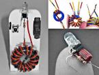
It all started with the fact that a few years ago a 6P45S lamp fell into my hands. Naturally, I immediately found that it can be assembled on it, namely, a Tesla coil on a radio tube. Collected, turned on - with difficulty earned. But in the end, he still burned this lamp because of his inexperience. After all, for the first time in my life I held a lamp in my hands :) Since then, I have collected many different ones, ranging from a spark gap to semiconductors. And here again the idea came to assemble a Tesla coil in a decent case, so as not to be ashamed to show it to friends. And then everything is on the wires, but on the wires. I started to collect according to the standard scheme, but decided to make some amendments. I wanted it to work in 2 modes. In 220V and 900V mode with interrupter. The voltage of 900V was going to be reached by assembling a multiplier by three. Based on the diagram, in order to switch the mode, you must simultaneously change the position of all switches.Capacitor C1 is sort of taken from a tape recorder. But it pierced all the time and I replaced it with a healthy Soviet one, from the receiver. The filament transformer wound itself, or rather the secondary with a millimeter wire. The master frequency generator was assembled on the NE555 timer. With four generation modes and fine tuning.


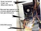
I decided to collect in the case from the ATX power supply. Although many dissuaded me from the metal case, I did not listen to them. The case beats with high-frequency current if the high-voltage winding is not grounded. I managed to get rid of this thanks to the high-pass filter. The tap from C3 and C4 goes to the case and all the RF current from the case goes through these capacitors.

In general, I started assembling ... I dug holes for all the switches, regulators and the lamp socket, began to push it into the case.

And then I realized that the multiplier does not fit. Without thinking twice, the function of the multiplier and chopper was replaced by the ionophone mode. This simplified the circuit a little, but I didn’t draw this circuit, because I immediately assembled it on the go :) The ionophone works almost like a breaker in the cathode, it only “interrupts” to the music. Transistor set N-P-N. I won’t tell Mark for sure - I tore it out of the monitor from the computer, it was somewhere in horizontal scan.

Here is the schematic diagram of the ionophone. Here you can change the generation frequency and duty cycle of the pulses.

A few photos of Tesla's assembly process at 6p45s. During the assembly, I conducted a “test drive” and if it didn’t work, I looked for jambs. By the way, here is a variable capacitor from a tape recorder, which constantly punched ...

In this photo, the same transistor on the radiator, on the left. You can try reading the title if you can.

A few words about the secondary (high-voltage winding). I wound it for a long time, I thought it would come in handy - and it came in handy! I wound it on a pipe from under food foil. Diameter about 3cm height 28cm and about 1500 turns of wire 0.16mm. I wound the primary 30 turns with a tap from every 5th. The entire Tesla weighs about 2kg.

Finished device:

A few photos in action))

With flash and without.


Well, a couple of videos demonstrating the operation of the generator.
On the video, where the coil works in the ionophone mode, the icons on the computer are constantly flickering if you notice - it was scissors on the keyboard and you pressed the buttons. Author of the design: Denis.
Discuss the article TESLA GENERATOR ON A LAMP