DIY photo relay. How to make a photo relay at home - the easiest way How to make a 12 volt photo relay yourself
I was personally concerned with the topic of how to organize additional lighting for seedlings in a not very bright room. The fact is that my tomato and pepper nursery is organized in a workshop in the garage (so as not to litter the house). So, there is one window to the west, and even darkened by the second floor terrace above it. In short, there is not enough light, however!
My actual lighting is organized by a structure of four LED spotlights suspended from the ceiling above the seedlings. But they need to be turned on in the morning and turned off in the evening (this is the life cycle of plants, unlike people who sleep and stay awake sometimes very intricately). Someone will say, what's the problem? Well, turn it on and off, or is that laziness?! For such angry people, I’ll explain that I have to constantly leave for two or three days a week. And this is already a problem. There is no one on the hacienda except video cameras, which, as you know, have other important tasks.
So, let's go! We need to make a photo relay that will turn on the lamps at dawn and turn them off in the evening at dusk. I took the circuit that was previously tested on the thermal relay for turning on and off the cooling fans in the power supply, which I wrote about earlier.
Just modified it slightly. Naturally, instead of a thermistor, I used a photoresistor FR-765. And the value of resistor R1 was increased to 820 kom. I tested the operation of the circuit on a breadboard, powering it from a laboratory source.
The existing 12V AC-DC converter was used as the power source for the circuit. It was ideally packaged together with the board in a small case. I did not use an indicator LED, since the indication is visually achieved by turning on four 100-watt spotlights (how can you not understand that - Hurray! It worked!).
I made the board layout in Sprint-Layuot, taking into account the layout in the case.

And then you need to make the board using the LUT method (laser ironing technology). I printed the board design on a laser printer (I have an HP) on yellow Chinese thermal paper (I like it the most out of everything I tried, as it consistently produces results when transferring the image onto foil fiberglass and is easily separated from it after transfer). In the printer settings, you need to set the maximum toner consumption. The board blank is sanded with polish and degreased with acetone. I make the board blank slightly larger than the required size in order to fix the paper with a pattern on it using 20 mm wide strips of masking tape (this is 20 mm wide tape, not strips), which are glued as shown in the photo and folded over the edges of the blank. Masking tape securely holds the paper on the workpiece when it is heated with an iron, does not melt and is easily removed later without leaving marks. I came to this after many different experiments as the most optimal method of fixation. That's about it.

Next is the LUT itself. The iron is set to maximum temperature. While it is heating up, I place the board blank on the board with the paper with the design facing up. I cover it with a sheet of ordinary office paper, folded in half. I also cover the top with a thin waffle towel folded in half, the kind that are now sold as rags for pennies. Then I begin to iron this sandwich with an iron with slight pressure for a minute and a half. Then I leave the workpiece to cool naturally. When it has cooled to room temperature, I carefully separate the paper from the copper layer of the workpiece.
It is important to maintain the warm-up time correctly so that the toner does not dry out. I overexposed it a bit, so any imperfections can be corrected with an acid-proof marker.
Next comes the actual bullying. I won’t describe it, the procedure is well known. After etching, wash the toner from the board with a swab moistened with acetone. This is what happened. Not God knows, but acceptable.

Next, cut the workpiece to size. To make this easy to do, when laying out the board in Sprint-Layout, I select the option with board outline. Along these lines I cut the board to size. What would you think? Scissors..., for metal. They cut PCB perfectly and there is no dust like from a hacksaw.

Next you need to tin the board. For this I use Rose alloy. This alloy has a melting point of about 99 degrees. In a small metal container with a non-stick coating (the molten alloy does not stick to it) with water on a portable gas stove, I melt a piece of Rose alloy (you need to add a little citric acid to the water, about a level teaspoon per glass of water), put the board there with a pattern on the molten alloy (similar to mercury, just as movable), I press it a little, moving the board back and forth, then turn the board over with the pattern facing up. Using a silicone spatula (of which there are a lot in household departments), I rub the molten alloy over the surface of the drawing, tinning it with a thin layer. This is what happened.


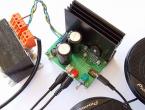
I tried manual micro-drills, but it’s not the same. Here the drill is fed strictly vertically (I use German carbide drills, which, although they cost 150 rubles each, are worth it) and the likelihood of breaking it is extremely small. Unless in an inadequate state, but in this case it is better to do something else, for example, look broadly at the world with a beefy gaze. Well, now we assemble the circuit on the board. This is what happened.

If the installation is completed correctly, the circuit starts immediately. The adjustment consists of adjusting the light thresholds of the relay using a trimming resistor. I set it to about 30 lux, allowing for some hysteresis given by feedback resistor R3.
Speaking of hysteresis. I also chose this circuit because when the relay operates at the boundary values (either in a thermal relay or in a photo relay), there is absolutely no bouncing of the relay contacts. Operations are clear. Although, we know how slowly the illumination changes during morning and evening twilight. But even in this case there are no marginal effects. Here is the finished product with the load power socket.

And this is it at work.

Well, now there’s one less problem to solve. And further. This photo relay can also be used in the mode of turning on the light with the onset of darkness and turning it off as the illumination increases. That is, like automatically turning on the lighting of something at night. To do this, only another relay contact is activated. This can be seen in the PCB drawing. All the best!
Photoresistors are semiconductor resistors whose resistance changes under the influence of electromagnetic radiation in the optical range.
The photosensitive element in such devices is a rectangular or round tablet pressed from a semiconductor material, or a thin layer of a semiconductor deposited on a glass plate - a substrate. The semiconductor layer on both sides has leads for connecting a photoresistor to the circuit. On circuit diagrams, a photoresistor is indicated by a resistor sign in a circle with side arrows.
The electrical conductivity of a photoresistor depends on the illumination. The brighter the lighting of the device, the lower the resistance of the photoresistor and the greater the circuit current.
These devices are used in automatic control circuits.
Photodiodes are a type of semiconductor diode. Until the photocell is refreshed, the blocking layer prevents the mutual exchange of electrons and holes between the semiconductor layers. When irradiated, light penetrates the “p” layer and knocks electrons out of it. The released electrons pass into the “n” layer and neutralize holes there. A potential difference arises between the photodiode terminals, which can be amplified by an electronic circuit to turn on automation and telemechanics devices.
Photodiodes are used to assemble power batteries in everyday life and on spacecraft.
Phototransistors are photocells based on transistors. This photo lighting relay uses a direct conduction phototransistor. To ensure that the light flux reaches the semiconductor crystal, the transistor cover is removed by simply removing it with pliers.
The photo relay in the figure above is used to automatically turn off or turn on actuators when the lighting changes.
Resistor R1, R2 and phototransistor VT1 represent a voltage divider based on transistor VT2. When phototransistor VT1 is illuminated, the voltage at the base of transistor VT2 decreases, transistor VT2 closes, and VT3 opens.
Relay K1 is triggered by the passage of current and opens contacts K 1-2, power supply to the load stops. Diode VD2 protects transistor VT3 from pulse noise that occurs when switching current in the winding of relay K1.
Relay contacts can be used to switch automation and telemechanics actuators.
Resistor R1 sets the sensitivity threshold, and R4 the illumination threshold.
LED HL1 indicates power on and operation mode of relay K1. Capacitor C1 prevents the relay from operating in the presence of interference. The power supply of the relay circuit is stabilized by the DA1 analog microcircuit. Capacitors C2, C3 are included in the anti-aliasing filter. Diode bridge VD1 is selected for a current of up to 1 ampere and a voltage of 50-100 Volts.
The device is equipped with a power switch S1 and a fuse F1.
The design of the VT1 phototransistor is simple: the “cap” of the transistor is removed with pliers, the transistor is glued to the M.8 nut, and the nut with the transistor is to a piece of glass and attached to the device.
|
Name |
Replacement |
Quantity |
Note |
||
|
Phototransistor |
according to the drawing |
||||
|
Transistor |
|||||
|
Transistor |
|||||
|
Resistors |
Type-A variables |
||||
|
Capacitors |
Electrolytes |
||||
|
Stabilizer |
A correctly assembled device should work immediately. When the slider of resistor R1 is in the upper position and resistor R4 is in the middle position, when lighting is applied to phototransistor VT1, relay K1 should operate. First check the relay by directly turning on the 12 volt power supply. Use resistor R1 to “adjust” the sensitivity of the photo relay at a given lighting R4.
List of radioelements
| Designation | Type | Denomination | Quantity | Note | Shop | My notepad |
|---|---|---|---|---|---|---|
| DA1 | Linear regulator | LM7812 | 1 | To notepad | ||
| VT1, VT2 | Bipolar transistor | MP42B | 2 | To notepad | ||
| VT3 | Bipolar transistor | MP25B | 1 | To notepad | ||
| VD1 | Rectifier diode | 1N4005 | 4 | To notepad | ||
| VD2 | Rectifier diode | 1N4007 | 1 | To notepad | ||
| VD3 | Diode | KD512B | 1 | To notepad | ||
| C1 | 10 µF | 1 | To notepad | |||
| C2 | Electrolytic capacitor | 1000 µF 16 V | 1 | To notepad | ||
| C3 | Electrolytic capacitor | 100 µF | 1 | To notepad | ||
| R1 | Variable resistor | 100 kOhm | 1 | To notepad | ||
| R2 | Resistor | 1 kOhm | 1 | To notepad | ||
| R3 | Resistor | 3.3 kOhm | 1 | To notepad | ||
| R4 | Variable resistor | 100 Ohm | 1 | To notepad | ||
| R5 | Resistor | 1.1 kOhm | 1 | To notepad | ||
| HL1 | Light-emitting diode |
An installation such as a photo relay for street lighting operates using a special photosensor, which is responsible for the level of light.
For those who decide to connect a photo relay, especially for street lighting, with their own hands, you should know that the photo sensor can be not only static, but also remote.
Most often, an external photosensor is built into an electrical panel.
Remote relays differ from static ones in that they have a number of rules that must be followed during operation.
For example, the circuit of an external photo relay must include a high-quality and sealed housing.
If you decide to purchase all the parts for the photo relay on your own and control of the device is entrusted to your shoulders, then you need to know that the sealed case must have a high degree of protection for the case in case of cloudy weather and other factors beyond your control.
Also, it is worth noting that mounting a photo relay for street lighting is a process that requires great attention
You must remember that the circuit must include protective functions against false signals, which most often appear as a result of interference.
Unlike low-quality photo relays for outdoor lighting, high-quality ones are able to work properly and emit signals only at the moment when it is really necessary.
Features of photo relay
If you want the installation to be carried out by professionals, then you should know that a function such as memory is a very important component of a high-quality photo relay.

For those who are going to install the device with their own hands, you need to clarify that the above function is very important.
The fact is that the shield on which the control panel is located will help you simplify your work with the device.
For example, in summer you need to turn on the street light quite late, and in winter - much earlier than in summer.
Thus, you will be able to set the necessary parameters on your own, which will ensure that the equipment operates only at the time when it is necessary.
Also, if you want the device circuit to be changed, you can reprogram the photo relay yourself.
In addition to all of the above, many device models are equipped with a special switch. As a rule, the device’s shield is equipped with this important element.
Thanks to the switch, control will become even more convenient than usual.
If the timer stops working or the equipment has any problems, you can turn off the device yourself.
Also, turning off the photo relay control in this way can be a good preventive measure.
The circuit of the most modern photo relays also includes a timer. It is with the help of a timer that managing it will become incredibly simple.
Typically, the switchboard of such device models is equipped not only with a control panel, but also with a timer.
A timer is a great addition that will help you significantly save electrical energy.
How is the relay connected?
In the image below, you can take a closer look at the technology by which the photo relay is connected.
This circuit is only suitable for those relays that are designed for street lighting.

Let's take a closer look at the diagram. So, instead of such a part as a sensor, a special LED is installed here, which is an indicator.
The operation of this LED occurs based on the principle of the photocell itself.
A certain LED is connected to the circuit itself, and two resistances are needed in order to control the sensitivity of the relay.
Such a kind of shield is needed so that any photodiode can have its own sensitivity to a particular type of lighting.
Speaking about the resistor, which is designated as R2, it is worth clarifying that it is needed in order to control the voltage emanating at first.
This voltage can regulate the device’s switching threshold.
Variety of photo relays
There are a certain number of different photo relays for street lighting. They differ from each other in their specialization and area of use.
Naturally, the control of different types of photo relays also differs.
The most common types are:
A device whose shield contains a photocell
The type of equipment whose shield contains a photocell is needed to turn on the lighting at dusk.
This device turns off as soon as the first rays of sunlight appear.

The control of the photo relay is fully automated through the switchboard, so connecting and setting up the device will not be difficult.
The photo relay has a transparent body that is able to protect the photocell and other mechanisms from a variety of climatic factors.
A relay containing a photocell and a timer
This equipment, like the one described above, is designed to control street lighting using automatic mechanisms.
The shield on which the timer is located allows you to control the duration of the lighting through it.
That is, using the connection control panel, you can manually enter the necessary time intervals at which the lighting needs to turn on.

After a certain period, after the lighting reaches a sufficiently high level, the photo relay will automatically turn off, thereby significantly saving you on energy costs.
Speaking about the connection timer, it is worth noting that there are different timers.
Some devices are equipped with weekly, annual or daily mechanisms. This way, you can orient the device the way you want.
Photo relay, the control of which allows you to adjust the response threshold
Controlling this type of relay is not much different from controlling the previous ones. There is a switch at the bottom of the device.
This switch is needed to adjust the threshold that determines how the photocell will operate.
If you set the regulator to plus, the element’s action will begin even when it is not particularly dark.
For example, if it starts to rain or thunderstorm, the photo relay will turn on automatically.
If you set the connection indicator to a negative value, the relay will work exclusively at night.
The correction function is indeed very popular among users of such devices.
What could be better than when the device works when it is convenient for you?
A structure that contains an external photocell
This type of equipment will help you control the mechanism in the following way: the main unit and the mechanism will be located at a distance of more than one hundred meters from each other.
You can place the electrical panel with the photo relay unit wherever you want.
Thanks to such control, you can place your device in the most weather-protected place.
Where is photo relay used?
Professionals consider the photo relay for street lighting to be the most acceptable device, both in terms of price and properties, with which you can adjust the response threshold.
You can also install photo relays for street lighting yourself. This model is best suited for city courtyards and summer cottages.
Don’t forget that the device can significantly reduce your electrical energy costs.

It should be noted that installing equipment that contains a photocell is actually a very easy task that even a beginner can handle.
It’s another matter when you need to install a device in which the photocell is a remote element. For the connection procedure, you will need professional skills and, of course, dexterity.
These two components will provide you with a high-quality option for connecting photo relays for street lighting.
A photo relay, the photocell of which is an external part, is ideal for locations such as huge warehouses and other large-scale establishments.
If you decide to purchase a photo relay that has a built-in timer, then be prepared for the fact that its price will be much higher than the price of a device without a timer.

But it’s worth clarifying that the high price will easily pay for itself, as it will allow you to set your own mode, which will save energy and allow the equipment to serve you longer.
A photo relay is a device for optimizing the lighting process, the control of which is incredibly simple and its functionality is extensive.
Now you don’t need to turn the light on and off yourself - the photo relay will do everything for you.
Every evening you have to turn it on, and every morning you have to turn it off. And if in good weather you can somehow put up with this, then in rain or snow... Therefore, the idea arises to automate the switching on and off of lamps. This is what a photo relay for street lighting does.
This device has a lot of names. In the literature you will find the name light-control switch or light-sensitive machine, and when communicating you can hear it as an illumination or light sensor, photosensor, twilight/twilight sensor or day/night. Perhaps there are others. But all this is about one device that turns on the lighting at dusk and turns it off at dawn.
Photo relays are made on the basis of a photoresistor or phototransistor, which change their parameters when the illumination changes. As long as enough light falls on them, the power circuit remains open. As darkness falls, the parameters of the photoresistor/transistor change and, at a certain value (set by settings), the circuit closes. In the morning, the process is exactly the opposite: when the illumination reaches a certain level, the power circuit is broken.
Specifications
First of all, you need to decide whether you want a photo relay for street lighting with an external or built-in light sensor. The remote sensor is small in size and is easier to protect from illumination; the device itself can be placed in the house, for example, in a panel. There are even models for DIN rail. A photo relay with a built-in light sensor can be placed near the lamp. It is only important to choose a place so that the light from the lamp does not affect the photosensor. This option is more convenient, for example, for .

Performance characteristics
Having decided on the type of sensor, we move on to the technical parameters:

To select a photo relay for street lighting, these characteristics are required. Their correct choice determines the performance of the device. But there are still some parameters that affect the correct operation of the device.
Customization options
There are several adjustments that allow you to customize the operation of the photo relay in each specific case. The problem is that the settings are made manually by turning the desired knob, and it is impossible to achieve absolutely identical parameters for several devices. There are always some differences in their work.

Using these settings, you can make the operation of the photo relay to automatically turn on the lighting of the area comfortable and eliminate false alarms.
Where to put
Choosing the right place to install a photo relay for street lighting is quite a quest. Several requirements must be taken into account:

With all this, the installation height of the photo relay is at the level of 1.8-2 m. This will make it possible to adjust the parameters “from the ground”. You can go higher, but you will need a stepladder/ladder or a chair/stool.
As you can imagine, finding such a place is not easy. There are several tricks that make the solution easier:

And another piece of advice from practice: it’s easier to adjust the operating parameters if the light sensor of the photo relay is located on the eastern or western wall. But only if there are no brightly glowing objects there. In this case, it is best to choose the side where the “exposure” is least.
Types of photo relay
As already mentioned, there is a photo relay with a built-in and remote light sensor. In addition, you can find the following varieties:

If you need one of the functions described above, it is not at all necessary to buy a photo relay with a motion sensor or timer. You can install a regular sensor and, in series with it, connect the desired device (motion sensor or timer). The functions will be the same, and repairs and replacement will cost less. If one of the parts in a photo relay with additional functions fails, you will have to change the device completely, and this option costs more than its “no frills” counterpart.
Connection diagrams for photo relays for street lighting
The purpose of a photo relay for street lighting is to supply power at nightfall and turn it off at dawn. That is, it is a kind of switch, only instead of a key there is a photosensitive element installed in it. Therefore, its connection diagram is similar: a phase is supplied to the photo relay, removed from its outputs and supplied to lamps or a group of lamps.

The simplest case is a diagram for connecting a photo relay to a lantern
Since the photo relay also requires power to operate, a zero is applied to the corresponding contacts; it is advisable to also connect the ground.
As we said earlier, you need to select a photo relay based on the power of the connected load. But one pattern is observed: with increasing power, prices increase significantly. To save money, you can supply power not through a photo relay, but through. It is designed for frequent power on/off, and can also be used to connect power using a light-sensitive element with a small connected load. In fact, it only turns on the magnetic starter, so only its power consumption is taken into account. And a powerful load can be connected to the terminals of the magnetic starter.

If, in addition to the day/night sensor, you also need to connect a timer or motion sensor, they are placed in series after the lighting relay. The order in which the movement/timer is set is not important.

If a motion sensor or timer is not needed, simply remove them from the circuit. She remains operational.
Installation and configuration
A photo relay with a built-in photosensor has three wires coming out of the housing. They are always connected the same way:
- Red goes to the load - a lantern, light bulbs, lamps.
- The brown or black wire is connected to the phase taken from the panel.
- The neutral from the bus with the “working zero” from the panel is connected to the blue one.

It is also advisable to ground the device by connecting it to the appropriate terminal on the housing. The wire cross-section is selected depending on the power of the connected load.
The relay is configured after it is installed and connected. When twilight sets in, wait until you are in a state where you would like the lighting to turn on. Take a small screwdriver and turn the adjustment wheel until the light comes on.
The procedure for connecting a photo relay with an external sensor is slightly different:
- connect the phase to terminal A1 (L) (at the top of the device);
- set zero to terminal A2 (N);
- from the output (depending on the model, it may be located in the upper part of the housing, then designated L’ or in the lower part of the housing), the phase is supplied to the lighting fixtures.
One of the connection options is in video. A circuit with a magnetic starter is implemented here.
DIY photo relay circuit
And this is a diagram of a simple photo relay. This device can be successfully used anywhere you want, for automatic illumination of the DVD tray, for turning on the light, or for signaling against intrusion into a dark closet :) Two circuit options are provided. In one embodiment, the circuit is activated by light, and in the other by its absence.
Scheme: I used a photoresistor in place of the photodiode and a relay for the load in place of LED-2.


It works like this: when light from the LED hits the photodiode, the transistor will open and LED-2 will start to glow. The sensitivity of the device is adjusted using a trimming resistor. As a photodiode, you can use a photodiode from an old ball mouse. LED - any infrared LED. The use of infrared photodiode and LED will avoid interference from visible light. Any LED or a chain of several LEDs is suitable as LED-2. An incandescent lamp can also be used. And if you install an electromagnetic relay instead of an LED, you can control powerful incandescent lamps or some mechanisms.