Materials. Materials When to bleed your brakes
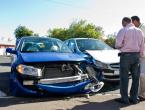
One of the conditions for safe movement on the road is a serviceable brake system. On classic VAZ models, brake mechanisms are installed, acting due to the friction force between different types of materials. The design of the VAZ 2101 brake system is simple, so you can monitor its technical condition and carry out repairs as necessary.
[ Hide ]
Features of the brake system
VAZ 2101 has two independent brake systems: working and parking. The first is activated while the car is moving. Its main mechanism is a hydraulic drive, due to which the gradual braking of the wheels is carried out.
The hydraulic drive consists of the following elements:
- pedal through which control is exercised;
- vacuum booster;
- pipelines;
- tank;
- cylinders: main (GTZ) and workers;
- brake mechanisms of the rear and front wheelsets.
The system uses two types of working mechanisms. Front disc brakes with calipers. At the rear, the wheelset is equipped with brakes in the form of drums, the mechanism of which also includes a parking brake.
The parking brakes are mechanically operated and controlled by the driver using the handbrake. They block the wheels and prevent spontaneous movement of the vehicle. Consist of lever, cable and brake pads.
For the smooth functioning of the brake system, it is necessary to periodically service it:
- change TJ;
- check the level of TJ;
- bleed the hydraulic drive to remove air pockets;
- check the degree of wear of the brake elements;
- check the condition of the cable on the handbrake and adjust its tension;
- adjust the brake controller.
So that the brakes do not fail on the way, you need to check the level of TJ before the trip. If it is not enough, air can enter the system, which threatens to reduce the effectiveness of the brakes. In addition, a decrease in the amount of fluid in the brake system indicates a leak and damage to the brake line. Air is expelled from the system by pumping. A weak tension of the handbrake cable threatens to fail the parking brake, so the tension of the cable must be controlled and adjusted if necessary.
According to the regulations, it is necessary to change the TJ every two years, regardless of the mileage. If this is not done, the braking efficiency will decrease over time. The liquid is hygroscopic. When it accumulates a lot of moisture, it boils at lower temperatures, which is dangerous when moving at high speeds. Excessive moisture is also the cause of corrosion of the elements of the brake system.
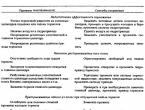
Main malfunctions and ways to eliminate them

How to bleed the brake system
Bleeding the brakes is necessary when air enters the brake system. The main drawback of the hydraulic drive is that the presence of air in the TJ significantly reduces the transmission of force. This is because air has the ability to compress. Therefore, when it enters the system, at the moment of compression, the volume of the working fluid changes and the force does not reach the mechanisms properly.
Airiness is the cause of inefficient brake operation:
- the wheels seize unevenly and not at the same time;
- while driving, brake pedal dips occur from time to time.
All this can lead to an emergency situation on the road. Therefore, this problem must be addressed as soon as it is discovered.
Air enters the system for various reasons. The pipelines are located under the machine, so they constantly experience shock loads, become covered with dirt, which leads to oxidative processes. As a result, potholes and cracks appear on them. On the front drive there are rubber parts that wear out quickly.
Air enters the actuator during scheduled maintenance. Brake fluid has a certain lifespan, so it needs to be changed periodically. During the replacement, the brake system may become airy. There is a high probability of air ingress during repair or during the replacement of brake elements.
Bleeding the hydraulic brakes helps to expel the air. Pumping is carried out in a strict sequence. We start work with the right wheel located at the back, since it is the most remote from the GTZ. Then we follow as we approach the GTZ: rear left, right front wheel and the last left wheel is pumped in front.

When hanging the wheels, it is necessary to provide for the failure of the car, so the wheels must be securely fixed with wheel chocks. When working on lifting devices, it is not necessary to jack up and hang out the wheels.
To carry out the pumping procedure, you need to prepare the necessary tools and materials:
- a set of keys;
- new TJ;
- container for draining the waste liquid;
- a rubber or silicone hose with a suitable diameter, preferably transparent, in order to observe the condition of the fluid flowing out.
In addition, you will need an assistant who will drive in the cabin and carry out the commands of the second participant. There is a wiggle option in which you can do without an assistant, but this is for experienced motorists. Before pumping the system, you need to check all its connections for leaks. If a leak is found, it must be eliminated, otherwise pumping will not make sense.
For proper bleeding, you need to know that the VAZ 2101 brake system is a dual-circuit one. Both circuits are independent of each other. This is necessary so that if one fails, the second remains operational, and the driver can stop the car. The division into contours is carried out in the GTZ. It is possible that it is enough to pump only one of the circuits. For example, after the repair of one of the working cylinders.
The pumping procedure consists of a sequence of steps:
- In order for the wheel fittings to be available, the car must be driven into a pit or installed on a flyover. We put the car on the handbrake or substitute supports so that it does not roll.
- First, work begins in the engine compartment. Raise the hood and unscrew the cap on the tank with TJ.
- Check how much liquid is in the tank. The maximum level is considered the norm. If it's not, add it.

- At the next stage, we move under the car and pump the right rear wheel first. Remove the cap protecting the fitting. We tear off the fitting with a key and immediately twist it back to make it easier to unscrew.
- We put on one of the ends of the prepared hose on the fitting. The second is lowered into a container into which a little TJ is poured.

- At this time, the assistant sits in the cab in the driver's seat. He presses the pedal 3 to 5 times, then squeezes it out completely and holds it in the depressed position.
- A person working under the machine unscrews the fitting half a turn.

After that, bubbly liquid will flow from it through the tube. The pedal must be depressed.
- When the TJ stops flowing, fasten the fitting.
- We repeat the operation until TA begins to enter the container, in which there are no air bubbles.
- When performing the procedure, it is important to control the level of TJ in the tank. If the liquid is not enough, it is necessary to add, maintaining the level at the maximum.
- Having pumped the hydraulic drive of the wheel, remove the hose, tighten the fitting and put on the protective cap.
- Then we continue similar work on each wheel according to the required sequence.
When the system is fully pumped, you need to check the stroke of the brake pedal. If it fails, you need to check the tightness of the lines.
Thus, the VAZ 2101 brake system does not have a complex design. Therefore, you can independently monitor the serviceability of its elements, perform periodic maintenance, diagnose and troubleshoot. It is important not to forget to bleed the brake system after repairing and replacing the brake fluid.
Replacing the brake fluid on the VAZ.
Cars of the classic VAZ family (models 2101 - 2107) are equipped with a traditional hydraulic brake system with front disc and rear drum brakes. All models are equipped with identical brake drums - these parts, their purpose, device, principles of operation and maintenance will be discussed in this article.
Brakes VAZ "Classic" - device, features and operation
VAZ "Classic" cars (models from 2101 to 2107) were equipped with a traditional hydraulic brake system. We have repeatedly written about this type of brakes, so here we will only talk about the main points. In this system, the force required to actuate the brakes mounted on the wheels is generated using the master brake cylinder when the driver presses the pedal. The increased pressure from the master cylinder is transmitted through the lines to the wheel cylinders, which move (in disc brakes) or push apart (in drum brakes) the pads.
The wheels of VAZ-2101 - 2107 vehicles are equipped with two types of brake mechanisms:
- Modern disc brakes - on the front wheels;
- Classic drum brakes - on the rear wheels.
Both of these mechanisms belong to friction brakes, that is, to brakes based on the friction force between moving and stationary parts. The difference between disc and drum brakes lies in the position, form of interaction of these parts.
But why was such a solution chosen - different types of brakes on the front and rear axles? There are several reasons. Firstly, at that time (the development of cars of this family was carried out in the 1970s), disc brakes were still rare, and, secondly, the more familiar (albeit less effective) drum brakes provided sufficient braking reliability for a rear-wheel drive passenger car of a small mass . So the chosen solution somewhat reduced the cost of production and maintenance of the car.
Regardless of the type of brake mechanism, it is driven by small hydraulic cylinders mounted on the wheels. An increase in pressure in the brake system causes pistons (which are cylinders inserted into calipers or hollow tubes) to move the pads, providing braking. When the pressure drops, the pistons under the action of the springs return to their original position, releasing the wheels.
The braking system of the VAZ "Classic" is highly reliable, as it consists of two independent hydraulic circuits that duplicate each other. Such a scheme ensures the performance of the brakes in the event of a malfunction of one of the circuits, and the failure of two circuits at once is an unlikely situation.
The device and principle of operation of drum brakes
Rear wheel brake parts:
1 - shield of the brake mechanism;
2 - wheel cylinder;
3 — the top coupling spring of pads;
4 - brake shoe;
5 - overlay pads;
6 - brake drum;
7 - locating pin;
8 - guide spring;
9 - lower coupling spring
The drum type brake consists of two main parts:
- brake drum ;
- Brake mechanism.
Brake drum. This part rotates with the wheel, also plays the role of a housing for the brake mechanism. The drum is made of metal, on its outer side there are threaded holes for studs with which the wheel is installed.
Brake mechanism. It is mounted on the brake shield, which, in turn, is fixedly fixed on the wheel hub. The mechanism consists of the following main parts:
- Brake pads with friction linings;
- Double-acting brake cylinder (has two pistons located on opposite sides);
- Coupling springs;
- Parking brake cable;
- The lever of a manual drive of brake pads.
This mechanism has two pads - front and rear (they got their name from their location relative to the car), between them in the upper part there is a brake cylinder, and the top and bottom of the pads are pulled together by springs. The parking brake cable and a number of other parts are also located here.
The principle of operation of drum brakes is very simple. The increase in brake fluid pressure caused by depressing the brake pedal causes the pistons in the wheel brake cylinder to expand, which in turn expands the pads associated with them. The pads rest against the drum, under the action of the piston they are pressed against its inner walls, and stop the rotation of the wheel. When the pressure in the system decreases, the force created by the cylinder drops, and due to the coupling springs, the pads move away from the drum.
Brake drums are subject to stringent requirements for reliability, strength, geometry, as well as the coefficient of friction of the inner surface. To date, two types of drums are used in VAZ-2101 - 2107 cars:
- Cast iron drums;
- Aluminum alloy drums with cast iron insert.
It is cast iron that optimally combines strength, reliability, and an acceptable coefficient of friction, as well as low cost and ease of manufacture. However, this metal is quite heavy and brittle, therefore, lighter and more durable drums made of aluminum alloys are often used (precisely alloys, since pure aluminum is too soft), but having a cast-iron insert on the inside, against which the pads rub.
Despite the fact that VAZ Classic cars have been discontinued (the last VAZ-2107 Seven rolled off the assembly line back in 2012), there are still a lot of them on Russian roads, so VAZ and many other manufacturers still manufacture brake drums for them. So the repair and maintenance of the brakes of the old "Zhiguli" in our time is not a problem.
Maintenance and repair of brake drums VAZ "Classic"
Rear drum brakes require regular maintenance and repair, and most often this is done in-house. Because most of the owners of the VAZ "Classic" are men, representatives of the older generation and, on the contrary, young people who are used to repairing their cars themselves.
Periodically it is necessary to check the main parts of the brakes:
- The condition of the inner surface of the drum;
- Condition and thickness of brake pads (more precisely, friction linings);
- Condition of the brake cylinder;
- Integrity and geometry of other components.
Since drum brakes are hidden from view, the drum must be removed to service, diagnose and repair them. This is done in the following order:
- Raise the rear of the car using a jack;
- Remove wheel;
- Unscrew the two fixing bolts;
- Screw these bolts into the technological holes, remove the drum (the bolts will push the drum out at the stop).
Now you can check the main components or further disassemble the brake mechanism.
Brake pads. They are considered operable as long as the thickness of the friction linings is 1.5 mm or more. Otherwise, they must be replaced. Also, the pads must be replaced if serious damage, grooves, any deformations, etc. are found on the pads. If the pads are dirty, they must be cleaned and washed with solvents.
Brake drum. The nominal inner diameter of the drum is 250 mm, with an increase in diameter of 1 mm or more, the drum must be replaced. If grooves, irregularities or other shallow damage are found on the inner surface of the drum, it can be bored, but with the above tolerance of not more than 1 mm. A larger increase in the inner diameter leads to a decrease in the strength of the drum, which is fraught with deformations and its destruction during movement. Therefore, today it is easier and cheaper to replace the drum with a new one.
Wheel brake cylinder. This assembly must be disassembled, cleaned, checked the integrity of each part, and also make sure that there are no grooves or roughness on the mirror surfaces of the pistons and cylinder. If surfaces are damaged, they can be sanded, but this may lead to a change in the dimensions of the parts, which is unacceptable. When assembling the cylinder, it is necessary to install new seals, and sometimes caps.
Special attention should be paid to drum brakes in several cases:
- The appearance of noise in the wheels, especially during the braking of the car - this can occur due to contamination of the brake mechanism, as well as due to uneven or critical wear of the friction linings and drum, breakage of springs and other elements;
- Uneven trajectory of the car during braking - this usually indicates a failure of the wheel cylinder, but sometimes this behavior of the car is caused by the complete wear of the pads of one wheel;
- An increased level of vibration during braking - this indicates either uneven or complete wear of the pads or drum.
In all these cases, it is necessary to make repairs, since malfunctions and wear of the pads and drums increase the danger of driving the car.
With proper maintenance and timely replacement of faulty or exhausted parts, the VAZ-2101 - 2107 rear drum brakes will serve reliably, ensuring your safety for many years.
This brake system has two circuits that provide independent drive of the front and rear wheel brakes. Both circuits are actuated from one pedal 17 (see Fig. Diagram of the brake system), which, using a bracket, is attached together with the clutch pedal to the front panel of the body.
Scheme of the brake system VAZ 2101, 2102
1 - protective casing of the front brake; 2, 18 - pipelines connecting two front brake caliper cylinders; 3 - support; 4 – hydraulic drive tank; 5 - stoplight switch; 6 – parking brake lever; 7 - adjusting eccentrics of the right rear brake; 8 - fitting for bleeding the hydraulic drive of the rear brakes; 9 - pressure regulator; 10 - stop signal; 11 - rear brake wheel cylinder; 12 - the lever of the manual drive of the pads and the expansion bar; 13 - adjusting eccentric of the left rear brake; 14 - brake shoe; 15 - rear cable guide; 16 - guide roller; 17 - brake pedal; 19 - fitting for bleeding the hydraulic drive of the front brakes; 20 - brake disc; 21 - master cylinderIn addition to the brake pedal, the hydraulic drive includes the main brake cylinder 21, the reservoir 4 of the master cylinder, the rear brake pressure regulator 9, the brake mechanisms of the front and rear wheels together with the working cylinders and pipelines.
Master brake cylinder VAZ 2101, 2102
Hydraulic brake master cylinder
 1 - cork; 2 - cylinder body; 3 – the piston of a drive of back brakes; 4 - washer; 5 – the piston of a drive of forward brakes; 6 - sealing ring; 7 - locking screws; 8 - piston return springs; 9 - spring plate; 10 - clamping spring of the sealing ring; 11 - spacer ring; 12 - inlet; A - compensation hole (gaps between the sealing ring 6, spacer ring 11 and piston 5)
 The brake master cylinder is attached to the clutch and brake pedal bracket. Pistons 3 and 5 (see Fig. Hydraulic brake master cylinder) actuate different circuits. Both pistons take their initial position under the action of springs 8, which press the pistons all the way into the screws 7. The tightness of the pistons in the cylinder is ensured by four sealing rings 6. The housing is closed at the front
cork 1.
Pedal assembly
Pedals 6 (see Fig. Details of the bracket of the clutch and brake pedals) and 19 are suspended on the bracket 1 by means of an axle made in the form of a bolt.
Clutch and brake pedal bracket parts
 1 - pedal bracket; 2 - nuts; 3 - spring washer; 4 – the internal plug of a pedal of a brake; 5 - outer bushings of the brake pedal; 6 – brake pedal; 7 - remote bushing; 8 - retraction spring of the brake pedal; 9 - outer bushings of the clutch pedal; 10 - spring hook; 11 - buffer; 12 - thrust bolt of the clutch pedal; 13 - servo spring; 14 - clutch pedal bushing; 15 – withdrawal spring of the clutch pedal; 16 - thrust washer; 17 - pedal pads; 18 - the axis of the pedals; 19 - clutch pedal; 20 - clutch pedal pusher
 Axis 18 is fixed with nut 2 in the holes of the cheeks of the bracket. On the axis between the cheeks of the bracket and the distance sleeve 7, the inner sleeves 4 and 14 of the clutch and brake pedals are clamped. Pedals are pivotally mounted on these bushings, in the hubs of which outer bushings 5 and 9 are pressed in. Pushers 20 are pivotally attached to both pedals, acting on the pistons of the hydraulic cylinders. The reverse travel of the clutch pedal is limited by the buffer 11 mounted on the head of the bolt 12. The main cylinders of the clutch release drive and the brake drive are attached to the bracket shelf.
Pressure regulator VAZ 2101, 2102
A pressure regulator 9 is connected to the rear brake drive circuit (see Fig. Brake system diagram - above), which adjusts the pressure in the rear brake drive depending on the position of the body relative to the rear axle beam, i.e. depending on vehicle load. It acts as a restrictor valve, automatically cutting off the flow of brake fluid to the rear brakes, reducing the chance of rear wheel skidding when braking.
The regulator is mounted on the body bracket and connected to the rear axle beam through the torsion lever 12 (see Fig. Details of the pressure regulator drive) and rod 7. The other end of the torsion lever acts on the piston 10 (see Fig. Rear brake pressure regulator in non-working position) .
Pressure Regulator Drive Parts
 1 - pressure regulator; 2 – axis of the regulator drive lever; 3 - dirt cap; 4 - locking plate; 5 - bolt with spring washer; 6 - rear axle; 7 – thrust connecting the pressure regulator drive lever with the bracket of the rear axle beam; 8 - bolt nut; 9 - plastic sleeve; 10 - spacer sleeve; 11 – a bolt of fastening of draft; 12 - pressure regulator drive lever; 13 – a nut for fastening of a bracket to a body; 14 - spring washer; 15 - flat washer; 16 - bracket for fastening the pressure regulator drive lever; 17 - rubber bushing
 Rear brake pressure regulator in non-working position
 A - normal pressure cavity; В – cavity of regulated pressure; P is the force transmitted by lever 4 of the regulator drive; 1 – regulator body; 2 - spacer sleeve; 3 - sealing ring; 4 – regulator drive lever; 5 - gasket; 6 - plug; 7 - rubber seal; 8 - spring plate; 9 - piston spring; 10 - piston
 Fluid enters cavity A from the master cylinder, and from cavity B it exits into the wheel cylinders of the rear brake drive.
The force P acting on the piston from the torsion lever increases as the body approaches the axle beam and decreases as the body moves away from the rear axle beam.
Before the pressure regulator begins to act, piston 10 abuts against plug 6 under the action of force P and spring 9. In this case, gaps are formed through which cavities A and B communicate, i.e. the pressure in them will be the same and equal to the pressure in the hydraulic brake drive.
When the brakes are applied, the rear of the car rises by inertia and, consequently, the pressure on the piston from lever 1 decreases. The force of fluid pressure on the upper end of the piston with a larger surface area at some point exceeds the pressure force of the fluid acting on the piston from below, and the piston will go down until it stops in the seal 7. At the same time, the cavities A and B will be separated, and different pressures will be created in them: in the cavity A, the pressure Pa will be equal to the pressure in the main cylinder, and in the cavity B, the pressure Pv will be less by the value that determines the balance of the piston, which is under the action of pressure Pa and Pb, spring 9 and the force of the torsion lever. Thus, partial or complete separation of cavities A and B by piston 10 regulates the braking torque on the rear wheels.
Brake mechanism of the front wheel VAZ 2101, 2102
The brake mechanism of a forward wheel is disk. It consists of the ones shown in Fig. Front wheel brake mechanism (Details of the front wheel brake caliper) caliper 12 (4) complete with working cylinders 17, brake disc 18, two brake shoes 16 (11), connecting fingers 8 (8) and pipelines.
Front wheel brake
 1 - fitting for pumping the drive of the brake mechanism; 2 - connecting tube of working cylinders; 3 – wheel cylinder piston; 4 - wheel cylinder retainer; 5 - brake shoe; 6 - sealing ring; 7 - dust cap; 8 - pins for fastening the pads; 9 – a bolt of fastening of a support to an arm; 10 – rotary fist; 11 – caliper mounting bracket; 12 - support; 13 - protective cover; 14 - cotter pin; 15 - clamping spring pads; 16 - brake pads; 17 - wheel cylinder; 18 - brake disc
 Front wheel brake caliper parts
 1 - piston; 2 - dust cap; 3 - sealing ring; 4 – support with cylinders; 5 – a connecting tube of brake cylinders; 6 - air outlet fitting; 7 - clamping spring pads; 8 – fingers of fastening of brake pads; 9 - cotter pins; 10 - springs; 11 - brake pads
 The caliper is attached to the bracket 11 with two bolts 9, which are locked by bending the bolts of the locking plates to the edge. The bracket 11, in turn, is attached to the flange of the steering knuckle 10 together with the protective cover 13 and the swing arm. The caliper has a radial groove through which the brake disc 18 passes and two transverse grooves for accommodating brake pads 16. The lugs of the caliper have two windows with guide grooves in which two opposite cylinders 17 are installed. To fix the cylinders relative to the caliper, a spring lock is installed in the cylinder 4, included in the side groove of the caliper.
Each cylinder has a piston 3 (1), which is sealed with an elastic rubber ring 6 (3). It is located in the groove of the cylinder and tightly compresses the surface of the piston. The cylinder cavity is protected from contamination by a rubber cap 7 (2).
The working cavities of the cylinders are interconnected by pipeline 2 (5). A fitting 1 (6) is screwed into the outer cylinder for bleeding the front brake drive circuit, into the inner cylinder - a hose fitting for supplying brake fluid.
Piston 3 rests against brake pads 16, on which pads 5 are glued. The pads are mounted on pins 8 and are pressed against them by springs 15 (7). Pins 8 are held in the cylinder by cotter pins 14 (9).
The brake disc 18 is attached to the wheel hub with two dowel pins.
Brake mechanism of the rear wheel VAZ 2101, 2102
The brake mechanism of a back wheel of drum type, with self-adjusting pads. Brake pads 3 with pads 7 (see Fig. Rear wheel brake mechanism), wheel cylinder 1 and other parts are mounted on the brake shield, which is attached to the flange of the rear axle beam. A package of plates is attached to the bottom of the shield with two rivets, one of which is a support for the lower ends of the brake pads. To regulate the gap between the shoes and the drum, eccentrics 8 are used, on which the shoes rest under the action of coupling springs 5 and 10.
 1 – wheel cylinder; 2 – the lever of a manual drive of pads; 3 – block of a brake; 4 – a cup and a basic rack of pads; 5 – a cable of a drive of a lay brake with a cover; 6 - lower coupling spring; 7 - friction lining; 8 - an eccentric for adjusting the gap between the block and the drum; 9 - spacer bar; 10 - upper coupling spring
 In the housing 4 (see Fig. Details of the wheel cylinder) of the wheel cylinder, there are two pistons 2, which are bursting with a spring 7 with support cups 5. Seals 3 are pressed against the end of the pistons by the same spring.
Wheel cylinder parts
 1 - protective cap; 2 - piston; 3 - sealant; 4 - wheel cylinder housing; 5 - spring cups; 6 - air outlet fitting; 7 - spring;
 Stops are pressed into the pistons, into the grooves of which the upper ends of the brake pads rest. The outlet of the pistons from the cylinders is sealed with rubber caps 1. To bleed the rear brake drive, a fitting 6 is screwed into the cylinder.
This brake system has two circuits that provide independent drive of the front and rear wheel brakes. Both circuits are actuated from one pedal 17 (see Fig. Diagram of the brake system), which, using a bracket, is attached together with the clutch pedal to the front panel of the body.
Scheme of the brake system VAZ 2101, 2102
1 - protective casing of the front brake; 2, 18 - pipelines connecting two front brake caliper cylinders; 3 - support; 4 – hydraulic drive tank; 5 - stoplight switch; 6 – parking brake lever; 7 - adjusting eccentrics of the right rear brake; 8 - fitting for bleeding the hydraulic drive of the rear brakes; 9 - pressure regulator; 10 - stop signal; 11 - rear brake wheel cylinder; 12 - the lever of the manual drive of the pads and the expansion bar; 13 - adjusting eccentric of the left rear brake; 14 - brake shoe; 15 - rear cable guide; 16 - guide roller; 17 - brake pedal; 19 - fitting for bleeding the hydraulic drive of the front brakes; 20 - brake disc; 21 - master cylinderIn addition to the brake pedal, the hydraulic drive includes the main brake cylinder 21, the reservoir 4 of the master cylinder, the rear brake pressure regulator 9, the brake mechanisms of the front and rear wheels together with the working cylinders and pipelines.
Master brake cylinder VAZ 2101, 2102
Hydraulic brake master cylinder
1 - cork; 2 - cylinder body; 3 – the piston of a drive of back brakes; 4 - washer; 5 – the piston of a drive of forward brakes; 6 - sealing ring; 7 - locking screws; 8 - piston return springs; 9 - spring plate; 10 - clamping spring of the sealing ring; 11 - spacer ring; 12 - inlet; A - compensation hole (gaps between the sealing ring 6, spacer ring 11 and piston 5) The brake master cylinder is attached to the clutch and brake pedal bracket. Pistons 3 and 5 (see Fig. Hydraulic brake master cylinder) actuate different circuits. Both pistons take their initial position under the action of springs 8, which press the pistons all the way into the screws 7. The tightness of the pistons in the cylinder is ensured by four sealing rings 6. The housing is closed at the front
cork 1.
Pedal assembly
Pedals 6 (see Fig. Details of the bracket of the clutch and brake pedals) and 19 are suspended on the bracket 1 by means of an axle made in the form of a bolt.
Clutch and brake pedal bracket parts
1 - pedal bracket; 2 - nuts; 3 - spring washer; 4 – the internal plug of a pedal of a brake; 5 - outer bushings of the brake pedal; 6 – brake pedal; 7 - remote bushing; 8 - retraction spring of the brake pedal; 9 - outer bushings of the clutch pedal; 10 - spring hook; 11 - buffer; 12 - thrust bolt of the clutch pedal; 13 - servo spring; 14 - clutch pedal bushing; 15 – withdrawal spring of the clutch pedal; 16 - thrust washer; 17 - pedal pads; 18 - the axis of the pedals; 19 - clutch pedal; 20 - clutch pedal pusher Axis 18 is fixed with nut 2 in the holes of the cheeks of the bracket. On the axis between the cheeks of the bracket and the distance sleeve 7, the inner sleeves 4 and 14 of the clutch and brake pedals are clamped. Pedals are pivotally mounted on these bushings, in the hubs of which outer bushings 5 and 9 are pressed in. Pushers 20 are pivotally attached to both pedals, acting on the pistons of the hydraulic cylinders. The reverse travel of the clutch pedal is limited by the buffer 11 mounted on the head of the bolt 12. The main cylinders of the clutch release drive and the brake drive are attached to the bracket shelf.
Pressure regulator VAZ 2101, 2102
A pressure regulator 9 is connected to the rear brake drive circuit (see Fig. Brake system diagram - above), which adjusts the pressure in the rear brake drive depending on the position of the body relative to the rear axle beam, i.e. depending on vehicle load. It acts as a restrictor valve, automatically cutting off the flow of brake fluid to the rear brakes, reducing the chance of rear wheel skidding when braking.
The regulator is mounted on the body bracket and connected to the rear axle beam through the torsion lever 12 (see Fig. Details of the pressure regulator drive) and rod 7. The other end of the torsion lever acts on the piston 10 (see Fig. Rear brake pressure regulator in non-working position) .
Pressure Regulator Drive Parts
1 - pressure regulator; 2 – axis of the regulator drive lever; 3 - dirt cap; 4 - locking plate; 5 - bolt with spring washer; 6 - rear axle; 7 – thrust connecting the pressure regulator drive lever with the bracket of the rear axle beam; 8 - bolt nut; 9 - plastic sleeve; 10 - spacer sleeve; 11 – a bolt of fastening of draft; 12 - pressure regulator drive lever; 13 – a nut for fastening of a bracket to a body; 14 - spring washer; 15 - flat washer; 16 - bracket for fastening the pressure regulator drive lever; 17 - rubber bushing Rear brake pressure regulator in non-working position
A - normal pressure cavity; В – cavity of regulated pressure; P is the force transmitted by lever 4 of the regulator drive; 1 – regulator body; 2 - spacer sleeve; 3 - sealing ring; 4 – regulator drive lever; 5 - gasket; 6 - plug; 7 - rubber seal; 8 - spring plate; 9 - piston spring; 10 - piston Fluid enters cavity A from the master cylinder, and from cavity B it exits into the wheel cylinders of the rear brake drive.
The force P acting on the piston from the torsion lever increases as the body approaches the axle beam and decreases as the body moves away from the rear axle beam.
Before the pressure regulator begins to act, piston 10 abuts against plug 6 under the action of force P and spring 9. In this case, gaps are formed through which cavities A and B communicate, i.e. the pressure in them will be the same and equal to the pressure in the hydraulic brake drive.
When the brakes are applied, the rear of the car rises by inertia and, consequently, the pressure on the piston from lever 1 decreases. The force of fluid pressure on the upper end of the piston with a larger surface area at some point exceeds the pressure force of the fluid acting on the piston from below, and the piston will go down until it stops in the seal 7. At the same time, the cavities A and B will be separated, and different pressures will be created in them: in the cavity A, the pressure Pa will be equal to the pressure in the main cylinder, and in the cavity B, the pressure Pv will be less by the value that determines the balance of the piston, which is under the action of pressure Pa and Pb, spring 9 and the force of the torsion lever. Thus, partial or complete separation of cavities A and B by piston 10 regulates the braking torque on the rear wheels.
Brake mechanism of the front wheel VAZ 2101, 2102
The brake mechanism of a forward wheel is disk. It consists of the ones shown in Fig. Front wheel brake mechanism (Details of the front wheel brake caliper) caliper 12 (4) complete with working cylinders 17, brake disc 18, two brake shoes 16 (11), connecting fingers 8 (8) and pipelines.
Front wheel brake
1 - fitting for pumping the drive of the brake mechanism; 2 - connecting tube of working cylinders; 3 – wheel cylinder piston; 4 - wheel cylinder retainer; 5 - brake shoe; 6 - sealing ring; 7 - dust cap; 8 - pins for fastening the pads; 9 – a bolt of fastening of a support to an arm; 10 – rotary fist; 11 – caliper mounting bracket; 12 - support; 13 - protective cover; 14 - cotter pin; 15 - clamping spring pads; 16 - brake pads; 17 - wheel cylinder; 18 - brake disc Front wheel brake caliper parts
1 - piston; 2 - dust cap; 3 - sealing ring; 4 – support with cylinders; 5 – a connecting tube of brake cylinders; 6 - air outlet fitting; 7 - clamping spring pads; 8 – fingers of fastening of brake pads; 9 - cotter pins; 10 - springs; 11 - brake pads The caliper is attached to the bracket 11 with two bolts 9, which are locked by bending the bolts of the locking plates to the edge. The bracket 11, in turn, is attached to the flange of the steering knuckle 10 together with the protective cover 13 and the swing arm. The caliper has a radial groove through which the brake disc 18 passes and two transverse grooves for accommodating brake pads 16. The lugs of the caliper have two windows with guide grooves in which two opposite cylinders 17 are installed. To fix the cylinders relative to the caliper, a spring lock is installed in the cylinder 4, included in the side groove of the caliper.
Each cylinder has a piston 3 (1), which is sealed with an elastic rubber ring 6 (3). It is located in the groove of the cylinder and tightly compresses the surface of the piston. The cylinder cavity is protected from contamination by a rubber cap 7 (2).
The working cavities of the cylinders are interconnected by pipeline 2 (5). A fitting 1 (6) is screwed into the outer cylinder for bleeding the front brake drive circuit, into the inner cylinder - a hose fitting for supplying brake fluid.
Piston 3 rests against brake pads 16, on which pads 5 are glued. The pads are mounted on pins 8 and are pressed against them by springs 15 (7). Pins 8 are held in the cylinder by cotter pins 14 (9).
The brake disc 18 is attached to the wheel hub with two dowel pins.
Brake mechanism of the rear wheel VAZ 2101, 2102
The brake mechanism of a back wheel of drum type, with self-adjusting pads. Brake pads 3 with pads 7 (see Fig. Rear wheel brake mechanism), wheel cylinder 1 and other parts are mounted on the brake shield, which is attached to the flange of the rear axle beam. A package of plates is attached to the bottom of the shield with two rivets, one of which is a support for the lower ends of the brake pads. To regulate the gap between the shoes and the drum, eccentrics 8 are used, on which the shoes rest under the action of coupling springs 5 and 10.
1 – wheel cylinder; 2 – the lever of a manual drive of pads; 3 – block of a brake; 4 – a cup and a basic rack of pads; 5 – a cable of a drive of a lay brake with a cover; 6 - lower coupling spring; 7 - friction lining; 8 - an eccentric for adjusting the gap between the block and the drum; 9 - spacer bar; 10 - upper coupling spring In the housing 4 (see Fig. Details of the wheel cylinder) of the wheel cylinder, there are two pistons 2, which are bursting with a spring 7 with support cups 5. Seals 3 are pressed against the end of the pistons by the same spring.
Wheel cylinder parts
1 - protective cap; 2 - piston; 3 - sealant; 4 - wheel cylinder housing; 5 - spring cups; 6 - air outlet fitting; 7 - spring; Stops are pressed into the pistons, into the grooves of which the upper ends of the brake pads rest. The outlet of the pistons from the cylinders is sealed with rubber caps 1. To bleed the rear brake drive, a fitting 6 is screwed into the cylinder.
This is the main element that is responsible for the safety of the vehicle on the road. Modern technologies make it possible to stop a car in a matter of fractions of a second, which cannot be said about the brakes of domestic cars. A separate place in the ranking is occupied by the VAZ-2101 brake system, which differs from subsequent ones in the absence of a vacuum brake booster. This article will discuss the improvement of the braking system of the domestic penny.
Tuning front and rear brakes VAZ-2101
The standard braking system of the VAZ-2101 cannot boast of good performance and has long been outdated
Tuning the brake system of a car is carried out in several stages. First you need to upgrade the front and rear brakes, replacing the standard discs with similar products from the VAZ-2112, which you immediately need to buy with suitable calipers in the kit. These are ventilated discs that have ellipsoid grooves on the surface, which contributes to the self-cleaning of the brake pads, improves the quality of braking.
Brake discs from the VAZ-2112 are placed on the front axle without any additional modifications. It is only necessary to make new fasteners for the calipers, because due to the difference in the size of the disks, the old fasteners will not fit. For this, high-quality steel or titanium is used, about seven millimeters thick. And also be sure to change the old brake hoses for new products.
Kopek is equipped with rear drum brakes, which greatly complicates their modernization. To install new ventilated discs, it will be necessary to modify the rear axle shaft so that its diameter matches the diameter of the ventilated brake disc. To do this, you will have to contact, since this cannot be done without special equipment. Similarly to the previous version, fasteners for calipers are made. Such efforts will be justified, since disk products do not collect water and do not freeze, unlike drum products. When installing axle shafts, it is necessary to install bearings and it is important to monitor their condition. Loose bearings can cause brake damage and accidents. Now the brakes can be connected via standard lines.

Due to these changes, you will have to buy a set of fourteen-inch wheels, since the old thirteen-inch ones will not fit on larger wheels. Such a replacement of wheels will positively affect the stability of the car.
Pay attention to the presence of a brake pressure regulator in the brake mechanism of your car. The opinions of the owners of kopecks were divided about its presence. Some owners believe that the brake regulator should be removed from the car's brake system as unnecessary and impractical to use.
However, the VAZ-2101 brake force regulator guarantees an even distribution of brake forces. In the absence or poor performance of the regulator, the front brakes will be ahead of the rear brakes in braking. This will lead to skidding of the rear axle of the car, which is unsafe on the road. Therefore, for a complete car, be sure to install a brake force regulator.
Installation of a vacuum brake booster on a VAZ-2101
VAZ-2101 is the only car from the VAZ family that is not equipped with a vacuum booster. VUT is responsible for the softness and information content of the brake pedal. Experts advise installing a vacuum brake booster on the VAZ-2101 from the eight. In addition to the vacuum booster, you will need to purchase a bracket for installing the booster on the car body and the main brake cylinder from VAZ-21213, three new tees from a penny, several copper brake pipes for brake cylinders from the classics. You will also need a brake tank hose, if the regular one is not enough, a radiator drain plug, washers and fasteners that are selected in place during installation.
You need to start work by removing the master cylinder, the rod from the brake pedal and the pin that holds the pedal assembly. The hole from the stud will serve as one of the mounts for the bracket. It remains to mark and drill three more holes. We finalize the bracket by drilling reciprocal mirror holes on it for fastening. The stem will also need some work. It must be compressed from the horn side, where the pedal is put on, and the hole must be drilled to a standard diameter.
Next, we proceed directly to mounting the VAZ-2101 vacuum brake booster to the car body using a bracket. It is advisable to immediately fasten the amplifier to the bracket, since it will be harder to perform such actions in the engine compartment. When screwing the parts together, screw the nuts onto the bracket to ensure the nominal distance from the booster to the cylinder, which ensures the correct fit of the rod on the pedal.
A gasket about eight millimeters thick must also be installed between the bracket and the body. Then all the fasteners are tightened, the stem is fixed to the pedal.
Now it remains only to connect all the elements to the calipers using copper tubes that bend very well. We bend them according to the standard version. It remains to connect the hose from the manifold to the vacuum brake booster. However, at this stage a problem arises, since there is nowhere to connect it. There are two ways here. It is necessary either to buy a manifold 2103 with a fitting for a vacuum line, or to embed the fitting into a native product. For tie-in, it is necessary to remove the intake manifold, drill a hole for the fitting with a twelve millimeter drill and screw in the product. Then a hose is put on it, the connections are fixed with metal clamps.
It remains only to pump the brakes, and check the effectiveness of their work.

Summing up
As you can see, it is possible to improve the braking system even on a vehicle that was produced several decades ago. However, tuning the brakes is a very responsible job, your safety on the road and even life may depend on the result. And also remember that any intervention in the braking system of the vehicle is prohibited by law.
Brakes only if you are completely confident in your abilities and capabilities.