How is the pressure gauge attached to the pipe. Pressure gauge installation: rules and requirements. On a three-way valve
1. The scale must be clearly visible.
2. The approach to the pressure gauge must be free.
3. Depending on the installation height of the pressure gauge, the diameter of the device is selected:
up to 2 meters - diameter 100mm;
· from 2 to 3 meters - diameter 160mm;
Over 3 meters - the installation of a pressure gauge is prohibited.
4. Each pressure gauge must have a shut-off device (3x running valve, valve or cock)
Pressure gauge maintenance rules.
According to the technical instructions, land on "O"
Departmental inspection 1 time in 6 months.
State verification - 1 time in 12 months.
Remove and install pressure gauges only with a wrench.
In case of pressure pulsation, measures must be taken:
· at a small pulsation the compensator is welded;
· with a large pulsation, a special device is used - an expander with two chokes.
4. First aid for loss of consciousness (fainting), heat and sunstroke.
Ticket number 2
1. Parameters characterizing the reservoir.
Oil and gas accumulate in cracks, pores and voids in rocks. The pores of the beds are small, but there are many of them, and they occupy a volume sometimes reaching 50% of the total rock volume. Oil and gas are usually enclosed in sandstones, sands, limestones, conglomerates, which are good reservoirs and are characterized by permeability, i.e. the ability to pass fluids through. Clays also have high porosity, but they are not permeable enough due to the fact that the pores and channels connecting them are very small, and the fluid in them is held immobile by capillary forces.
Porosity refers to the proportion of void space in the total volume of the rock.
Porosity depends mainly on the size and shape of the grains, the degree of their compaction and heterogeneity. In the ideal case (sorted spherical grains of uniform size), the porosity does not depend on the size of the grains, but is determined by their mutual arrangement and can vary from 26 to 48%. The porosity of natural sandstone is, as a rule, much less than the porosity of fictitious soil, i.e. soil composed of spherical particles of the same size.
Sandstones and limestones have even lower porosity due to the presence of cementing material. The greatest porosity in natural soil is inherent in sands and clays, and it increases (in contrast to fictitious soil) with a decrease in the size of rock grains, since in this case their shape becomes more and more irregular, and, consequently, the grain packing becomes less dense. Below are the porosity values (in %) for some rocks.
Clay shale 0.5–1.4
Clays 6–50
Sands 6–50
Sandstones 3.5–29
Limestones and dolomites 0.5–33
With increasing depth due to increased pressure, the porosity of rocks usually decreases. The porosity of the reservoirs on which production wells are drilled varies within the following limits (in %):
Sands 20–25
Sandstones 10–30
Carbonate rocks 10–20
Carbonate rocks are usually characterized by the presence of cracks of various sizes and are estimated by the fracturing coefficient.
One of the characteristics of rocks is the granulometric composition, on which other physical properties largely depend. This term refers to the quantitative content of grains of different sizes in the rock (in % for each fraction). The granulometric composition of cemented rocks is determined after their preliminary destruction. The granulometric composition of rocks to a certain extent characterizes their permeability, porosity, specific surface, capillary properties, as well as the amount of oil remaining in the reservoir in the form of films covering the surface of the grains. They are guided during the operation of wells in the selection of filters that prevent the ingress of sand, etc. The grain size of most oil-bearing rocks ranges from 0.01 to 0.1 mm. However, usually when studying the granulometric composition of rocks, the following categories of sizes (in mm) are distinguished:
Pebbles, crushed stone > 10
Gravel 10–2
rough 2–1
large 1–0.5
medium 0.5–0.25
fine 0.25–0.1
Siltstone:
large 0.1–0.05
fine 0.05–0.1
clay particles< 0,01
Particles up to about 0.05 mm in size and their amount are determined by sieving on a set of sieves of the appropriate size, followed by weighing the residues on the sieves and determining the ratio (in%) of their mass to the mass of the initial sample. The content of smaller particles is determined by sedimentation methods.
The heterogeneity of rocks in terms of mechanical composition is characterized by the coefficient of heterogeneity - the ratio of the particle diameter of the fraction, which, with all finer fractions, is 60% by weight of the total mass of sand, to the particle diameter of the fraction, which, with all finer fractions, is 10% by mass of the total mass of sand ( d60/d10). For “absolutely” homogeneous sand, all grains of which are the same, the coefficient of heterogeneity Kn = d60/d10 = 1; Kn for rocks of oil fields ranges from 1.1–20.
The ability of rocks to pass liquids and gases through them is called permeability. All rocks are permeable to some extent. Under existing pressure differences, some rocks are impermeable, others are permeable. It all depends on the size of the communicating pores and channels in the rock: the smaller the pores and channels in the rocks, the lower their permeability. Typically, the permeability in a direction perpendicular to the bed is less than its permeability along the bed.
Pore channels are super- and subcapillary. In supercapillary channels with a diameter of more than 0.5 mm, liquids move, obeying the laws of hydraulics. In capillary channels with a diameter of 0.5 to 0.0002 mm, when fluids move, surface forces appear (surface tension, capillary forces of sticking, cohesion, etc.), which create additional forces of resistance to fluid movement in the reservoir. In subcapillary channels with a diameter of less than 0.0002 mm, the surface forces are so great that there is practically no movement of liquid in them. Oil and gas horizons mainly have capillary channels, clayey horizons have subcapillary channels.
There is no direct relationship between porosity and permeability of rocks. Sandy formations can have a porosity of 10–12%, but be highly permeable, and clayey formations, with a porosity of up to 50%, remain practically impermeable.
For the same rock, the permeability will vary depending on the quantitative and qualitative composition of the phases, since water, oil, gas, or mixtures thereof can move along it. Therefore, to assess the permeability of oil-bearing rocks, the following concepts are accepted: absolute (physical), effective (phase) and relative permeability.
Absolute (physical) permeability is determined when one phase moves in the rock (gas or homogeneous liquid in the absence of physical and chemical interaction between the liquid and the porous medium when the rock pores are completely filled with gas or liquid).
Effective (phase) permeability is the permeability of a porous medium for a given gas or liquid when the pores contain another liquid or gaseous phase. Phase permeability depends on the physical properties of the rock and the degree of its saturation with liquid or gas.
Relative permeability - the ratio of effective permeability to absolute.
A significant part of the reservoirs is heterogeneous in texture, mineralogical composition and physical properties vertically and horizontally. Sometimes significant differences in physical properties are found at short distances.
Under natural conditions, i.e. under conditions of pressure and temperature, the permeability of cores is different than under atmospheric conditions, it is often irreversible when reservoir conditions are created in the laboratory.
Sometimes the capacity of the reservoir and the commercial reserves of oil and gas in the reservoir are determined by the volume of fractures. These deposits are confined mainly to carbonate, and sometimes to terrigenous rocks.
Usually, there is no strict regularity in the distribution of fracture systems over the elements of structures, to which oil and gas containing deposits are confined.
Permeability is usually estimated using the practical unit darcy, which is about 10-12 times less than the permeability of 1 m2.
The permeability unit of 1 darcy (1 D) is taken as the permeability of such a porous medium, when filtered through a sample of which with an area of 1 cm2 and a length of 1 cm at a pressure drop of 1 kg/cm2, the flow rate of a liquid with a viscosity of 1 centipoise (centipoise) is 1 cm3/s. A value equal to 0.001 D is called millidarcy (mD).
The permeability of rocks in oil and gas reservoirs varies from a few millidarcies to 2–3 D and is rarely higher.
There is no direct relationship between the permeability and porosity of rocks. For example, fractured limestones with low porosity often have high permeability, and, conversely, clays, sometimes characterized by high porosity, are practically impermeable to liquids and gases, since their pore space is composed of channels of subcapillary size. However, based on average data, it can be said that more permeable rocks are often more porous.
The permeability of a porous medium depends mainly on the size of the pore channels that make up the pore space.
2. Separators, purpose, device, principle of operation and maintenance.
During extraction and transportation, natural gas contains various kinds of impurities: sand, welded sludge, condensate of heavy hydrocarbons, water, oil, etc. The source of pollution of natural gas is the bottomhole zone of the well, which gradually collapses and pollutes the gas. Gas treatment is carried out in the fields, the efficiency of which depends on the quality of the gas. Mechanical impurities enter the gas pipeline, both during its construction and during operation.
The presence of mechanical impurities and condensate in the gas leads to premature wear of the pipeline, valves, blower impellers and, as a result, a decrease in the reliability and efficiency of the compressor stations and the gas pipeline as a whole.
All this leads to the need to install various process gas purification systems at the compressor station. At first, oil dust collectors were widely used at CS for gas purification (Fig. 3), which provided a sufficiently high degree of purification (up to 97-98%).
Oil dust collectors work on the principle of wet trapping of various kinds of mixtures in the gas. Impurities wetted with oil are separated from the gas stream, the oil itself is cleaned, regenerated and sent back to the oil dust collector. Oil dust collectors were more often made in the form of vertical vessels, the principle of operation of which is well illustrated in Fig. 3.
The gas to be purified enters the lower section of the dust collector, hits the impact shield 4 and, in contact with the oil surface, changes the direction of its movement. In this case, the largest particles remain in the oil. At high speed, the gas passes through the contact tubes 3 into the settling section II, where the gas velocity decreases sharply and the dust particles flow through the drainage tubes into the lower part of the dust collector I. Then the gas enters the baffle section III, where the final gas purification takes place in the separator device 1.
The disadvantages of oil dust collectors are: the presence of a constant irretrievable oil consumption, the need to clean the oil, as well as heating the oil in winter operating conditions.
At present, cyclone dust collectors are widely used as the first stage of cleaning at the CS, operating on the principle of using inertial forces to trap suspended particles (Fig. 4).
Cyclone dust collectors are easier to maintain than oil ones. However, the cleaning efficiency in them depends on the number of cyclones, as well as on the provision of operation of these dust collectors by the operating personnel in accordance with the mode for which they are designed.
The cyclone dust collector (Fig. 4) is a cylindrical vessel designed for the operating pressure in the gas pipeline, with built-in cyclones 4.
The cyclone dust collector consists of two sections: the lower baffle 6 and the upper settling 1, where the final cleaning of the gas from impurities takes place. In the lower section there are cyclone pipes 4.
The gas through the inlet pipe 2 enters the apparatus to the distributor and the star-shaped cyclones 4 welded to it, which are fixedly fixed in the lower grate 5. In the cylindrical part of the cyclone pipes, the gas supplied tangentially to the surface rotates around the inner axis of the cyclone pipes. Under the action of centrifugal force, solid particles and liquid drops are thrown from the center to the periphery and flow down the wall into the conical part of the cyclones and further into the lower section 6 of the dust collector. The gas after the cyclone tubes enters the upper settling section 1 of the dust collector, and then, already cleaned, exits the apparatus through the pipe 3. During operation, it is necessary to control the level of the separated liquid and mechanical impurities in order to remove them in a timely manner by blowing through the drain fittings. Level control is carried out with the help of sight glasses and sensors attached to fittings 9. Hatch 7 is used for repair and inspection of the dust collector during scheduled shutdowns of the compressor station. The efficiency of gas purification by cyclone dust collectors is not less than 100% for particles with a size of 40 μm or more, and 95% for particles of a dropping liquid.
Due to the impossibility of achieving a high degree of gas purification in cyclone dust collectors, it becomes necessary to perform the second purification stage, which is used as filter separators installed in series after cyclone dust collectors (Fig. 5)
The operation of the filter-separator is carried out as follows: the gas after the inlet pipe is directed to the inlet of the filtering section 3 with the help of a special baffle visor, where the liquid is coagulated and cleaned from mechanical impurities. Through the perforated holes in the housing of the filter elements, the gas enters the second filter section - the separation section. In the separation section, the gas is finally cleaned from moisture, which is captured using mesh bags. Through the drainage pipes, mechanical impurities and liquid are removed to the lower drainage collector and further to underground tanks.


For operation in winter conditions, the filter-separator is equipped with electric heating of its lower part, a condensate collector and instrumentation. During operation, mechanical impurities are trapped on the surface of the filter-separator. When the difference equal to 0.04 MPa is reached, the filter-separator must be turned off and the filter elements in it must be replaced with new ones.
As experience in the operation of gas transmission systems shows, the presence of two stages of purification is mandatory at underground gas storage stations, as well as at the first linear compressor station in the course, which receives gas from UGS facilities. After cleaning, the content of mechanical impurities in the gas should not exceed 5 mg/m3.
The gas supplied to the main compressor stations from wells, as noted, almost always contains moisture in the liquid and vapor phases in one or another amount. The presence of moisture in the gas causes corrosion of the equipment, reduces the throughput of the gas pipeline. When interacting with gas under certain thermodynamic conditions, solid crystalline substances-hydrates are formed, which disrupt the normal operation of the gas pipeline. One of the most rational and economical methods of dealing with hydrates with large volumes of pumping is gas drying. Gas dehydration is carried out by devices of various designs using solid (adsorption) and liquid (absorption) absorbers.
With the help of gas dehydration units at the head facilities, the content of water vapor in the gas is reduced, the possibility of condensate in the pipeline and the formation of hydrates is reduced.
3. Systems and schemes for collecting and transporting gas, their advantages and disadvantages
- Before starting work, the user must be sure that the pressure gauge (vacuum gauge, pressure gauge) is correctly selected in terms of measuring range and performance. The measuring range is optimally selected when the working pressure is located in middle third indication range.
- The instrument must be fixed in a location that is not subject to shock and positioned in such a way that it is freely accessible and easy to read.
- The connections must be tight.
- Between the pressure measuring point and the manometer it is recommended to install a locking device that allows the replacement of the measuring device and zero control in working order.
- Depending on the purpose of the pressure gauge, it can be equipped with stopcocks or valves.
- A location used on process equipment or piping to control pressure is called selection(impulse) pressure.
- The route connecting the pressure tap to the pressure gauge is called impulse line.
- Depending on the pressure, aggressiveness, fire hazard and explosiveness of the measured media, the impulse lines consist of copper, seamless steel or PVC pipes.
- The diameter of the impulse pipes and their thickness during installation are selected based on the length of the route, and the maximum working pressure of the medium.
- Impulse lines for measuring the pressure of controlled media must be laid in strict accordance with the wiring diagram of the automation of the facility, which indicates the length of the route and the full characteristics of the line: type of material used; section and wall thickness.
- Pressure taps (impulses) are usually installed on straight sections of pipelines and process equipment, taking into account bends, turns, elbows and tees, where an additional measurement error occurs due to the centrifugal force of the measured medium flow.
- Membrane separators, vessels: In the presence of aggressive, hot, highly viscous, contaminated or crystallising media, which must not penetrate the measuring element, media separators must be provided as separating devices. At the same time, the internal space of the pressure gauge and the separator is filled with a working fluid, which serves to transfer pressure from the separator membrane to the pressure gauge, which is selected depending on the measuring range, temperature and compatibility with the measured medium.
- When measuring the pressure of acids and alkalis, separation vessels are used to protect the inner surface of the sensitive element of the device, the inner cavity of which is filled with water, light mineral oils, glycerin, ethyl alcohol, etc.
- Protection of sensitive elements against overload Note: If the medium to be measured is pulsating or if water hammer is likely to occur, prevent their direct effect on the sensitive elements.
- To do this, it is necessary to ensure the damping of hydraulic shocks by installing a throttle (reducing the cross section of the pressure channel) or by installing an adjustable throttle device.
- Also, to eliminate and smooth out the pulsation of the measured pressure of liquids, steam and gases at compressor stations, in pumps, process equipment and pipelines, leading to failure of the transmission mechanism of the devices, a special throttle is installed in the pressure gauge fitting, which allows to significantly reduce the diameter of the inlet.
- If the measuring range is chosen to be less than the magnitude of short-term pressure surges in order to obtain more accurate readings, it is necessary to protect the sensing element from damage. To do this, an overload protection device must be installed - a device that closes instantly with a water hammer, with a gradual increase in pressure, its closing occurs gradually.
- The amount of closing to be set therefore depends on the characteristic of the change in pressure over a certain period of time.
- Another option would be to use a gauge with overpressure resistance (internal protection).
- Gauge mount: if the connection leading to the pressure gauge does not provide sufficient fastening stability, thenprovide appropriate fixing elements on the wall and/or pipe, otherwise, supply the pressure gauge with a capillary connection.
- Damping of oscillations (vibrations) of the measuring system: If shocks cannot be prevented by appropriate mounting, vibration-resistant liquid-filled devices (water filling) should be used.
- As a rule, the pressure gauge is installed with a vertically standing dial. In case of deviations, you need to pay attention to the position sign on the dial.
- It is recommended to use a turnbuckle or swivel nut to set the pressure gauge to a position that provides maximum reading.
- Do not screw in and out of the pressure gauge by the body - for this purpose, surfaces are provided for a wrench on the connecting fitting.
- Gaskets, washers made of leather, fiber, lead or soft copper must be used as a seal at the junction of devices with a pressure source..
- For instruments used to measure oxygen pressure, use only copper and lead gaskets.
- For instruments measuring acetylene pressure, it is forbidden to use gaskets made of copper and copper alloys containing more than 70% copper.
- If the device is located below the pressure taps, the measuring line must be thoroughly flushed before connection in order to remove solids.
- To compensate for internal pressure, some types of devices have holes closed with a stopper, which are labeled " CLOSED" And " OPEN". In the normal state, the opening for merging with the atmosphere is closed (the lever is in the "CLOSED" position). Before checking or / and after installation, as well as before starting work, these devices are filled with air, i.e. the lever is brought to the "OPEN" position.
- When pressure testing or purging pipelines or containers, do not subject the pressure gauge to a load exceeding the limit mark on the dial. Otherwise, the device must be locked or dismantled.
- Depressurize the measuring element before dismantling the pressure gauge. Otherwise, remove voltage from the measuring line.
- For leaf spring gauges, do not remove the tightening screws on the top and bottom flanges.
- Residues of measured media in dismantled pressure gauges can be hazardous to people, the environment and premises. Necessary security steps should be taken.
- Pressure gauges whose sensing elements are filled with water or an aqueous mixture must be protected from freezing.
- The measuring line must be manufactured and installed in such a way as to ensure the absorption of the load due to tension, vibration and thermal effects.
- If the measured medium is a gas, then at the lowest point it is necessary to provide for the possibility for drainage, if liquid, then at the highest point to provide for the possibility for deaeration.
- When working with gases and liquids containing solid impurities, cutting devices (separators) are provided, which can be separated from the installation through shutoff valves during its operation and freed from impurities.
For certain types of equipment (pipelines, powerful steam and hot water boilers), there are strict standards for the maximum allowable pressure. Exceeding these standards entails a disruption in the production process, as well as a serious danger to workers and the environment. In order to comply with safety regulations, technical pressure gauges are installed on such equipment, regular checks of the readings of which can prevent accidents.
Requirements for technical gauges
- high accuracy;
- protection against temperature extremes;
- high pressure protection;
- anti-corrosion protection.
Information on how to install technical pressure gauges is contained in Chap. 6.4 Rules for the operation and installation of various types of boilers and Ch. 2.8 of the Rules for the operation and installation of pipelines (PB 10-573-03).
To install a pressure gauge, a steam boiler pipe is usually used in front of a valve that regulates the water supply to the steam boiler. If there are several low-power boilers in the boiler room, fed from one pipe, then it is allowed to install one powerful pressure gauge before entering the boilers. Hot water boilers are equipped with pressure gauges at the water inlet (before the valve) and at the outlet (before the safety valve), as well as on the suction and discharge units of the circulation pumps.
According to the established norms, it should be done once a year. The verification process consists of a visual inspection of the device and verification of its readings with the readings of the control pressure gauge. If the verification period has expired or there is no mark on the pressure gauge body indicating that its verification was carried out on time, it is forbidden to use the device.
A manometer is a device for measuring water pressure in a water supply system. With its help, accurate indicators of the working environment are obtained at any section of the pipeline. Depending on the operating conditions, there are several types of such sensors.
Pressure gauge device for measuring water pressure
Pressure gauge device
The manometer has a simple design. The device distinguishes between the case and the scale on which the measured values are marked. The housing contains a tubular spring. It can be replaced by a two-lamellar membrane. The manometer has a holder, a sensitive element and a tribco-sector mechanism.
The arrow of the device is an indicator. It can make one revolution around its axis. Gears are used to transmit rotation to the arrow. The design of the device contains a toothed sector and a leash. Between the gears and the teeth of the device there is a special spring that eliminates the possibility of backlash.
Classification of pressure gauges and principle of operation

Digital Water Pressure Gauge
Depending on the features of the operation, pressure measuring devices are classified into the following types:
- Piston. They include a cylinder in which the piston is located. During operation, the medium acts on one part of the pump, and the load presses on the other. The slider moves by moving the arrow. It shows a certain value on the scale of the device.
- Liquid. They include a tube with liquid and a movable plug. When using such a device, the working medium presses on the plug, changing the level of liquid in the tube. The arrow of the device is set in motion.
- Deformation. Inside such products there is a membrane, which, when deformed, activates a pointer above the scale.
Modern pressure measuring devices are divided into mechanical and electronic. In the first case, the design of the device is as simple as possible. The electronic pressure gauge contains a contact assembly that can more accurately measure the pressure of the working medium. Such devices are widely used in industry. They are used as exemplary models for testing pneumatic components and adjusting regulators in various automated systems. Many electronic pressure gauges store data on peak pressure values for a certain period of operation.
Depending on the features of the work, the devices are:
- Stationary - installed only on certain units. Dismantling such pressure gauges will not work. Often a water pressure regulator is used with them.
- Portable - can be installed on different units and used in various systems. A distinctive feature of the models is their small size.
Many of the pressure gauges are used in the heating systems of country houses and apartments in multi-storey buildings. Others are used to service industrial facilities.
Mounting Features

The layout of the pressure gauge on the pipeline
The installation of the pressure gauge is only possible at a depressurized facility. The device is placed in working position. Usually it is written in the instructions. It also specifies the installation permits. The pressure gauge is mounted using a wrench. In order not to overload the body of the device, it is necessary to ensure that the tightening torque does not exceed 20 N * m.
You can install a pressure gauge to measure the water pressure in the water supply in the following ways:
- Straight. The device is mounted in the places marked in the design documents, for example, before and after the valves. The installation point houses the adapter. It is connected to the pipeline by welding or screwing. The pressure gauge is installed in a direct way in cases where the system is stable, without pressure surges.
- With a three way valve. If the measurement data needs to be checked for atmospheric pressure, a three-way valve is installed for this purpose. Atmospheric air is supplied through it. Changing a pressure gauge installed in this way does not require interruption of the medium supply.
- Using impulse tube. It protects the pressure gauge mechanism from pressure drops. An adapter must be used to install the device. Then a tube, a three-way valve and the sensor itself are placed on the pipeline. This method is used in cases where the working environment has a working temperature that exceeds the standard values.
To ensure stable operation of the pressure gauge and reduce the risk of malfunctions, certain installation requirements are observed:
- Installation is carried out in such a way that it is easy to take measured indicators, carry out maintenance and repair.
- If the pressure gauge is placed at a height of 2-3 m, the case diameter must be greater than 160 mm. Installation of the device at a height of more than 3 m is prohibited.
- A quick check of the pressure sensor can be ensured by installing a three-way valve in the design, which should be located between the pipe and the pressure gauge.
- When installing equipment in conditions of possible exposure to external adverse factors (high temperature, precipitation), it is necessary to create additional protection for the device. Siphons and buffer elements are chosen for this task.
- The thermal insulation of the sensor prevents freezing.
- When connecting a pressure gauge to measure pressure, it is necessary to bleed the gas that has entered the system. To do this, the fixing nut on the fitting is not screwed up a little.
Measuring equipment that has not been tested and does not have a sealed seal on the case is not allowed to be used in communication networks. At the end of the test period, the sensor is removed and sent for diagnosis. If there is a crack on the glass of the device, or visible damage appears on the body, the sensor is disposed of.
 The meter is installed in a vertical position. This ensures that the data can be read correctly. The sensor scale can have a slope of no more than 30 degrees. The device must be well lit and protected from direct sunlight. It is undesirable to install a device whose arrow does not return to its original position after being turned off.
After installing the device and putting the system into operation, it should not be loaded immediately. It is better to raise the pressure gradually, avoiding sudden pressure surges. Such measures can extend the life of the sensor.
When installing a pressure gauge for measuring pressure, check the tightness of the connection between the measuring device and the fitting. For this, FUM tape or thread is usually used. To make the docking site more reliable, use a sealant. All products must comply with the operating conditions. For example, for superheated steam with a temperature above 130 degrees, it is unacceptable to use FUM tape, which is designed for a maximum heating of 95 degrees. Some installation companies use tow as an insulator, which should not be allowed.
Pressure gauges for measuring pressure in the water supply network should not be repaired on your own. When choosing the type of device, it is important to study the parameters of communications in which it will be used.
The pressure measurement error depends on the instrumental errors of the measuring instruments, the operating conditions of the pressure gauges, the methods of pressure sampling and its transmission to the instruments. When choosing the measurement limits of a manometer, they are guided by the values of the measured pressure and the nature of its changes. With a stable measured pressure, its value should be 3/4 of the measuring range of the device, and in the case of variable pressure, 2/3. To exclude the possibility of the formation of explosive and combustible mixtures, pressure gauges designed to measure the pressure of gases such as oxygen, hydrogen, ammonia are painted in blue, dark green, and yellow in accordance with the standard.
Rules for installing pressure gauges at industrial facilities, pressure extraction and its transmission to devices using impulse lines are regulated by internal standards that guide the installation of measuring devices. The main provisions of these guidance materials are discussed below.
Pressure gauges indicating and with remote transmission of readings, as a rule, are installed near pressure sampling points in a place convenient for maintenance. The exception is pressure gauges used for in-reactor control and pressure control in devices located at NPPs in restricted areas. Modern serial pressure transducers cannot be placed inside the active zone; therefore, they are located at a considerable distance from pressure sampling points, which leads to an increase in the inertia of instrument readings. In this case, it should be taken into account that the presence of a liquid column in the impulse line creates a systematic error of readings, which will have a negative or positive sign, depending on whether the pressure gauge is located above or below the pressure tapping point. The impulse lines of differential pressure gauges are long, the limit value of which is 50 m.
Pressure sampling is carried out with the help of pipes connected to the pipeline or the internal space of the object where pressure is measured. In general, the tube should be made flush with the inner wall, so that the protruding part does not create flow deceleration. When measuring pressure or pressure difference in liquid media, it is not recommended to take pressure from the lower and upper points of the pipeline, so that sludge and gases do not get into the impulse lines, in case of gaseous media - from the lower points of the pipeline, so that condensate does not get into the impulse lines .
When measuring pressure and rarefaction in gas ducts, air ducts, dust pipelines, it often becomes necessary to smooth out pressure pulsations and separate suspended particles.
Rice. 1. :
1 - cyclone; 2 - dust pipeline; 3 - metal wall; 4.5 - tubes; 6 - hole with plug
On fig. Figure 1 shows the installation of cyclone I on the pressure line in the dust pipeline 2, which has a metal wall 3. The dust-air mixture is supplied to the cyclone by tube 4 tangentially, pressure is taken to the device from the cyclone from its middle part by tube 5. In the cyclone, suspended particles are separated and periodically removed from it through hole 6. To smooth out pulsations, chokes are installed in front of the measuring device. The length of the lines from the pressure tap to the device must ensure that the measured medium is cooled down to ambient temperature. With the help of switch taps, one pressure gauge or draft gauge can be connected to several pressure or vacuum taps.

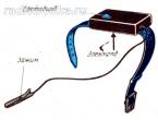
Rice. 2. :
1 - pressure gauge; 2 - three-way valve; 3 - shut-off valve; 4 - bent ring tube
Scheme of installing pressure gauge 1 on the pipeline shown in fig. 2. To ensure the possibility of turning off the pressure gauge, purging the line and connecting the control pressure gauge, a three-way valve 2 is used; when measuring pressure over 10 MPa (100 kgf / cm2), as well as when controlling the pressure of the radioactive coolant, an additional shut-off valve 3 is installed at the outlet of the pipeline. When measuring the pressure of media with temperatures above 70 °C, tube 4 is bent into a ring in which water is cooled and steam condenses. At nuclear power plants, the impulse lines of pressure gauges and differential pressure gauges working with radioactive media are purged into a special drainage system.
When measuring the pressure of aggressive, viscous and liquid-metal media, membrane and liquid separators are used to protect pressure gauges and differential pressure gauges. Diagram of a pressure gauge with a diaphragm seal is shown in fig. 3.

Rice. 3. :
1, 2 - aggressive and neutral environment
1 - measured medium; 2 - separating vessel; 3 - line filled with a neutral medium
Aggressive medium is supplied under the membrane 7, the lower part of which and the adjacent walls are covered with fluoroplast. The space above the membrane 2 and the inner cavity of the manometric spring are carefully filled with organosilicon liquid. In order for the pressure above the membrane to correspond to the measured pressure during the measurement process, it is necessary that the stiffness of the membrane be much less than the stiffness of the sensing element. When using liquid separators (fig. 4) this limitation is absent.

Rice. 4. Scheme of installation of pressure gauges with separating vessels when the density of the measured medium is less than the density of the neutral (a) and more (b):
The neutral separating liquid that fills the part of the separating vessel 2, the measuring chamber of the device and the lines between them 3 must differ significantly in density from the measured medium 1 and not be mixed with it. On fig. 4, and the density of the aggressive medium is less than the separating one, and in Fig. 4, b - more.
When measuring the pressure difference, the differential pressure gauges must be connected in such a way that the medium filling the impulse lines does not create errors due to the difference in density or height of the liquid columns in them. The lines should not have horizontal sections, the minimum angle of inclination should be at least 5 °. When measuring the pressure difference between water and steam, the measuring chambers of differential pressure gauges must first be filled with water.
Not only the efficiency of the operation of technological facilities, but in many cases safety also depends on the correctness of the readings of pressure gauges; therefore, pressure gauges and other pressure devices are subject to periodic verification. For most instruments, the calibration period is one year. If the instruments are operated in conditions of high vibration and temperature, this period may be shortened. Verification of instruments is carried out by representatives of metrological services.
For verification of working pressure devices, exemplary instruments and devices that reproduce pressure are used. For deadweight testers, these functions can be combined. When checking pressure gauges designed to measure the pressure of reactive gases, such as oxygen, deadweight testers filled with oil cannot be used.