Auto tester for continuity of wires without battery circuit. What is continuity and how to properly ring wires, cables and various electrical equipment. Search for cable cores with a dial tone
In many cases, it is not at all necessary to measure the resistance of a particular part. It is only important to make sure, say, that a circuit is intact, that it is isolated from another, that a diode or transformer winding is in good condition, etc. In such situations, instead of a pointer measuring device, a probe is used - its simplest substitute. The probe can be, for example, an incandescent lamp or a headset connected in series with the battery. Touching the remaining terminals of the lamp (or telephone) and the battery of the tested circuits, it is easy to determine the integrity of the circuits or judge their resistance by the glow of the lamp or clicks in the telephone. But, of course, the areas of use of such probes are limited, therefore, it is desirable to have more advanced designs in the arsenal of a measuring laboratory for a beginner radio amateur. We will get to know some of them.
Before proceeding with the adjustment of the assembled structure, it is necessary, as they usually say, to “ring out” its installation, that is, to check the correctness of all connections in accordance with the circuit diagram. Often, radio amateurs use for these purposes a relatively bulky device - an ohmmeter or an avometer, operating in the resistance measurement mode. But often such a device is not needed, it can be replaced by a compact probe, the task of which is to signal the integrity of a particular circuit. Such probes are especially convenient for “ringing” multi-wire bundles and cables. One of the schemes of such a device is shown in Fig. P-22. It has only three low-power transistors, two resistors, an LED and a power supply.
In the initial state, all transistors are closed, since there is no bias voltage on their bases relative to the emitters. If we connect the conclusions “to the electrode” and “to the clamp” to each other, a current will flow in the base circuit of the transistor VT1, the strength of which depends on the resistance of the resistor R1. The transistor will open, and a voltage drop will appear on its collector load - resistor R2. As a result, transistors VT2 and VT3 will also open, and current will flow through the HL1 LED. The LED will flash, which will serve as a signal that the circuit under test is working.
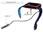
The peculiarity of the probe is its high sensitivity and relatively low current (no more than 0.3 mA) flowing through the measured circuit. This made it possible to make the probe somewhat unusual: all its parts are mounted in a small plastic case (Fig. P-23), which is attached to a watch strap (or bracelet). From below, to the strap (opposite the case), a metal plate-electrode is attached, connected to the resistor R1. When the strap is fastened on the arm, the electrode is pressed against it. Now the fingers of the hand will act as a probe probe. When using a bracelet, no additional electrode plate is needed - the output of the resistor R1 is connected to the bracelet.

The probe clamp is connected, for example, to one of the ends of the conductor, which must be found in the bundle or “ringed” in the installation. By touching the ends of the conductors on the other side of the bundle with your fingers in turn, they find the desired conductor by the appearance of the LED glow. In this case, between the probe and the clamp, not only the resistance of the conductor, but also the resistance of the part of the hand, turns out to be included. Nevertheless, the current passing through this circuit is enough for the probe to "work" and the LED to flash.
Transistor VT1 can be any of the KT315 series with a static coefficient (or simply a coefficient - as we will write further for brevity) of current transfer of at least 50, VT2 and VT3 - others, except those indicated on the diagram, of the corresponding structure and with a transfer coefficient of at least 60 ( VT2) and 20 (VT3).
The AL102A LED is economical (consumes a current of about 5 mA), but has a small glow brightness. If it is insufficient for your purposes, install the AL102B LED. But the current consumption will increase in this case by several times (of course, only at the moment of indication).
Power source - two batteries D-0.06 or D-0.1 connected in series. There is no power switch in the probe, because in the initial state (with the base circuit of the first transistor open), the transistors are closed, and the current consumption is negligible - it is commensurate with the self-discharge current of the power source.
The probe can generally be assembled on transistors of the same structure, for example, according to the one shown in Fig. P-24 scheme. True, it contains a few more details than the previous design, but its input circuit is protected from external electromagnetic fields, sometimes leading to false flashing of the LED. This probe uses silicon transistors of the KT315 series, which are characterized by a low reverse current of the collector junction over a wide temperature range. When using transistors with a current transfer ratio of 25..30, the input impedance of the probe is 10... ...25 MΩ. Increasing the input resistance is impractical because of the increased probability of false indication by external pickups and extraneous conductances.
Sufficiently large input resistance is achieved by using a composite emitter follower (transistors VT1 and VT2).
Capacitor C1 creates a deep negative feedback on the alternating current, excluding false indication from the effects of external pickups.
As in the previous case, in the initial mode, the device practically does not consume energy, since the resistance of the HL1VT3 circuit connected in parallel to the power source in the closed state of the transistor is 0.5 ... 1 MΩ. The current consumption in the indication mode does not exceed 6 mA.

You can correct the input resistance of the device by selecting the resistor R2, having previously connected a chain of resistors with a total resistance of 10 ... ... 25 MΩ to the input and achieving the minimum brightness of the LED.
But what if there is no LED? Then, instead of it, you can use in both versions a small-sized incandescent lamp for a voltage of 2.5 V and a current consumption of 0.068 A (for example, a MN 2.5-0.068 lamp). True, in this case, it will be necessary to reduce the resistance of the resistor R1 to about 10 kOhm and select it more accurately according to the brightness of the lamp with closed input conductors.
Probes with sound indication can cause no less interest among radio amateurs. The scheme of one of them, attached to the arm with a bracelet, is shown in fig. P-25. It consists of a sensitive electronic key on transistors VT1, VT4 and an AF generator assembled on transistors VT2, VT3 and a miniature phone BF1. The oscillation frequency of the generator is equal to the mechanical resonance frequency of the phone. Capacitor C1 reduces the effect of AC interference on the operation of the indicator. Resistor R2 limits the collector current of transistor VT1, and hence the current of the emitter junction of transistor VT4. Resistor R4 sets the highest volume of the phone, resistor R5 affects the reliability of the generator when the supply voltage changes.

Any miniature telephone (for example, TM-2) with a resistance of 16 to 150 ohms can be a BF1 sound emitter. The power source is a D-0.06 battery or an RTS53 element. Transistors - any silicon of the appropriate structure, with a current transfer coefficient of at least 100, with a reverse collector current of not more than 1 μA.
Details of the probe can be mounted on an insulating bar or board made of one-sided foil fiberglass. The bar (or board) is placed, for example, in a metal case in the form of a watch, to which a metal bracelet is connected. Opposite the emitter, a hole is cut out in the housing cover, and a miniature socket of the XT1 connector is fixed on the side wall, into which an extension conductor with an XP1 probe (it can be a crocodile clip) is inserted at the end.
A slightly different probe circuit is shown in Fig. P-26. It uses both silicon and germanium transistors. Moreover, it is not at all necessary to make the design small-sized, the indicator itself can be assembled in a small box, and the bracelet and probe can be connected to it with flexible conductors.
Capacitor C2 shunts the electronic key in alternating current, and the capacitor. SZ - power source.
It is desirable to select a transistor VT1 with a current transfer coefficient of at least 120 and a collector reverse current of less than 5 μA, and VT2 with a transmission coefficient of at least 50, VT3 and VT4 of at least 20 (and a reverse collector current of not more than 10 μA). The BF1 sound emitter is a DEM-4 capsule (or similar) with a resistance of 60 ... 130 Ohms.
Probes with audible indication consume slightly more current than the previous one, so it is advisable to turn off the power source during long interruptions in operation.

B.S. Ivanov. Encyclopedia of a beginner radio amateur
What does it mean to ring a wire? This means checking its integrity, that there is no cliff anywhere in its path.
In order to quickly ring the beginning and end of wires or cables, any section of the wiring, to find out which wire at the beginning corresponds to another wire at the end, you need a device that can do this job.
Such devices are multimeters and testers for calling electrical circuits.
Such devices are perfectly used not only in production, but also in everyday life. From several modes of operation, one can single out the "dialing" mode. Just such a mode is used by specialists to check the integrity of the electrical circuit.
How to call with a multimeter
First, let's figure out what quantities the device measures. These are current, voltage and resistance. At the moment we are interested in calling wires or cables with the help of this apparatus.
Before starting, you need to set the device to dialing mode. It is available for all devices with a special diode icon.
Then we need to check the performance of our device. Connect the probes that come with the device to the desired sockets. Shown in the picture below.
We close the probes with each other. You should hear a characteristic sound. This means that the electrical circuit is closed and there is no break between the probe wires.
The same can be done with the tested wire for its integrity. If the wire being tested is long and laid somewhere, for example, in a wall, then you can use another auxiliary extension wire.
It is worth remembering that all actions to search for a broken wire or its integrity must be carried out without applying 220 V voltage to the wire under test. Otherwise, the device will fail.
How to ring a stranded wire or cable if its end is at a great distance from its beginning?
The wires are stripped of insulation from both ends of the cable. Then they check the wires for a short circuit between themselves by touching the multimeter probes to each wire. If the device does not make a sound, then there is no short circuit.
After that, you can check the integrity of the wires in the cable. All cores from one end of the cable are twisted together, and the cores from the other end are checked by touching the wires with probes to each other. The device in this case should make a characteristic sound, which means the integrity of all wires in the cable.
If there is no sound when you touch a wire, then there is a break on the wire.
In the same way, you can call any wires in pairs, if required.
Such a continuity is good when there are many wires of the same color and it is impossible to determine which wire goes where.
Electrical continuity tester
There are a wide variety of wire and cable testers on the market. The difference between a tester and a multimeter is that its functionality is more modest.
The main purpose is to call the wires and check the voltage. Therefore, many types of testers are not only a continuity, but also as a voltage indicator.
It is quite natural that in each such device there are batteries for indication and signal, which need to be replaced as they are used or over time.
A simple dial can be made by yourself at home. To do this, you need to take a 4.5 V battery, a 3.5 V light bulb and a piece of wire. The connection scheme is the simplest.

One disadvantage of the simplest testers is the inability to test the resistance of high-resistance circuits.
Watch a video on how to use the simplest continuity test for electrical circuits.
Conclusion
You have learned what you need to find a malfunction in electrical circuits, check the integrity of the wires. Of course, this will not solve big problems if there are more complex problems.
To do this, you will have to use more sophisticated equipment and you cannot do without a specialist. In the following articles, we will try to reveal other issues that are no less relevant.
How to ring a wire with a multimeter - the nuances of the process
Often at home it is necessary to find the reason why one of the electrical networks does not work. For example, the lamp in the room does not light up. There are several reasons for this: the bulb in the lamp burned out, the contacts in the cartridge or in the switch burned out, the electrical wiring was broken. The worst reason is the last one. But how to determine that a break has formed in the wiring? There is only one option - to ring the electrical supply wire, for which you can use a multimeter. Of course, there are other options besides this device, but this one is the most reliable. So, how to ring the wires with a multimeter - the solution to the problem.

To begin with, using a multimeter, you can test the wiring for the magnitude of indicators such as current and voltage. In this case, the wires must be energized. A dial to determine the presence of a break is the determination of the magnitude of the resistance of the conductor, that is, it is present or absent. So, if the multimeter shows “0” on the display, then the wires are intact, and there is no break in them. If the resistance is shown on the display, then this indicates that there is a break. Basically, it's that simple. The only thing you need to pay attention to is that when testing the wiring for resistance, there should be no voltage in it.
Multimeter setup
First of all, you need to set up the device in ohmmeter mode. For you to understand how to do it correctly, look at the photo below, where all positions are indicated by arrows. But we are interested in the position of "Continuity", it is on it that the handle of the device must be set.

Now you need to check the tester itself. To do this, connect two probes (red and black) to each other, the display should show “zero” or an indicator slightly higher than it. This indicates that the device is working correctly.
Since our task is determined by the question of how to ring the wire, we are sure that other electrical elements that can accumulate electrical potential are not installed in the wiring. That is, we have a linear conductor either made of copper or aluminum.
Wire continuity
The wire dialing mode with a multimeter consists in the fact that it is necessary to connect the probes of the device to the two ends of the wire and determine if there is resistance in the wire. By the way, many testers (modern) have alarm functions. That is, you are testing, and the presence of resistance confirms the squeak of the device. Very comfortably.
But there is one catch. It is good if the wire is checked, which will only be used in the wiring. There will be no problems with connecting the probes, because the length of the wires of the probes themselves is quite short. But how to ring the wires that are already laid, for example, the old electrical wiring is checked.
Let's look at this with an example, all the same lamp. So, two wires are connected to it: phase and zero. For testing, it will be necessary to disconnect the wire connection to the light source and twist the ends of the two lines together. That is, it will be necessary to short-circuit the line, make a ring out of it. But keep in mind that before that it will be necessary to disconnect both wires from the supply circuits in the junction box. Now, right there in the switch box, you need to connect the probes to two wires and test with a multimeter.
And if the device shows a break, then your task is to repair the wiring or install a new one. In the event that you decide to make repairs, then you need to determine the location of the break. To do this, you will need to use special devices. For example, a domestic copy, which is called "Woodpecker". First, it will be necessary to apply voltage to the wiring, and only then to determine the location of the wire break.
This method of checking wires is also suitable for motorists. Often the ignition system fails just because the high-voltage wires do not work in it. Of course, the reason may not be in them, but this problem is present. Here everything is done in the same way as described above. The only thing is the indicators on the multimeter screen. So, if the device on the display shows numbers from 3.5 to 10 kOhm (the limits must first be set on the device itself), then such wires are considered intact. If the resistance value exceeds 10 kOhm, then there is a break in the wires, you will have to replace them with new ones. True, it is necessary to make a reservation that the specified range is not standard, everything will depend on the brand of the car. But as practice shows, the spread of permissible values \u200b\u200bcan be 2-4 kOhm.

In principle, all types of cables are tested according to the same principle. Even a generator based on a copper wire is checked for an open in the same way. We will not mention checking the armored wire or other types of power cables.
Conclusion on the topic
Our task is simple, to understand the question, how to check the cable with a multimeter for a break? Let's face it, this is the most reliable way, which uses the most versatile device. If you understand it, then at home it will not be difficult to determine whether there was a wire break or not.
How to check resistance with a multimeter
How to test a transformer with a multimeter
How to measure current with a multimeter
How to ring wires with a multimeter
Preparing the multimeter
In order to ring wires and cables, an inexpensive multimeter is suitable, which has a resistance measurement mode. Let's take the DT-838 multimeter as an example.

How to ring wires with a multimeter
For the continuity of wires and cables, two measurement modes are used - this is “200 Ω” and a sound image. The difference between these modes is that in the “200 Ω” mode, during a dial tone, the display shows a resistance value close to zero with a whole wire, and 1 if it is broken.
In the sound signaling mode, the display shows the resistance value during a dial tone and an audible signal is added. The appearance of a sound signal means the resistance of the wire is close to zero. And the absence of it, high resistance or wire breakage.
Such a sound alarm is convenient when dialing in hard-to-reach places where it is not possible to observe the multimeter display. However, before ringing the high-voltage wires with a multimeter in a car, the measurement limit is set to “20 K”, since the resistance of the whole high-voltage wire lies in the range from 3.5 to 10 K.

Wire ringing in buzzer mode
Before the wire is dialed by the multimeter, the probe with the black wire is inserted into the “COM” jack, and the red probe into the “ΩVmA” jack. The mode switch must be set to the measurement limit "200 Ω" or sound alarm. Before the continuity of wires and cables, the probes are connected to each other to check the operability of the device.
How to ring wires
Before measurements, it is important to strip the ends of the wires from insulation and remove the oxide from the cable cores. Oxide on the wires may have a high resistance that will be above the value limit of the instrument's selected resistance mode, giving false readings.
Before the dialing, you need to remove the mains voltage from the wiring, in the car, remove the terminals from the battery. If there are capacitors in the wire continuity circuit, then they need to be discharged by short-circuiting the output. All these precautions will help to avoid damage to the multimeter and give more reliable results.
For convenience, when dialing, special wire clips are used - "crocodiles". "Crocodile" is put on the probe and clamped on the wire section. The use of such clamps increases the convenience when working with wires, as hands are freed.
Short cables and wires can be called from one end, and long wires must be well cleaned of oxides and twisted together on one side. Then the dialing process is carried out only on one side. You can ring the wires without a multimeter. For such purposes, electricians use a specially made "ringing", consisting of a battery and a light bulb. Also, a sound generator and headphones are used to check cables and wires.

Battery chime with light bulb
Determining a fault in the wiring
Let's consider finding faults in the apartment network using the example of standard electrical wiring. Before electrical work, you need to remove the voltage from the introductory machine in the electrical panel. If the machine knocks out in the shield, then the order of finding a short circuit is as follows:
- They remove the voltage from the knocked-out introductory machine, unscrew the wires from the lower terminals of the machine, the cable from the lower terminals of the machine must go to the load.
- The disconnected wires of the phase and zero on the shield are ringing. If there is a short circuit, unwind all the wires in the first junction box from the electrical panel and ring them. Each wire in the box, before being untwisted, is marked with one twist under one number. Find the direction (room) of the electrical wiring with a short circuit.
- Before dialing, all lighting fixtures must be turned off in all rooms, plugs must be pulled out of sockets. If everything is turned off, and a short circuit is present in the junction box of this room, unwind the wires in the box and look for a short circuit with a multimeter, separately for each outlet and lighting. If a short circuit occurs when the lighting is on, the fault is sought in the lamp cartridge, chandelier.
- The found section of the wiring with a short circuit must be changed. If the wiring is hidden, then you need to open it (which is expensive) or run a cable channel from above the wall. The cable channel spoils the view a little, but the costs are minimal.
- If the wiring fault is in a break, then the place of the break is found when the introductory machine is turned on for a lack of voltage. The multimeter mode is set to "
750V", do not confuse with the resistance measurement mode, otherwise the multimeter will burn out. The exact location of the break can be found if you apply voltage to this section of the circuit and use special devices (domestic "Woodpecker").
If you find an open or short circuit in the wiring, remember what types of work were carried out in the apartment. This will help you find the wiring damage faster.
Also interesting articles

How to test a capacitor with a multimeter without soldering

How to check battery capacity with a multimeter
How to call wiring
In order to check the wiring in your home, the easiest way is to contact electricians. But the whole problem is that a municipal electrician will have to wait a very long time, and a private one will come right away, however, and his prices are high.
That is why it will not hurt you to master the simple skills of working with electrical wiring. After all, it is quite possible that one day this knowledge will be useful to you in life.
First of all, when working with electrical wiring - compliance with safety regulations.
How to check the wiring at the laying stage
Let's figure out what potential problems an electrician can expect while laying a new electrical wiring.

Usually, new wiring is laid either in special strobes or along bare walls. Then the walls are plastered and further finishing is performed. Therefore, the first check is carried out before the start of plastering. Otherwise, it may be that in order to fix the problem, you will have to ditch the walls again and open the plaster.
At this stage, problems can be for two reasons: due to the mistakes of the builders (concrete workers or finishers) or due to the mistakes of electricians.
To avoid wiring problems, which can be caused by builders' mistakes, you need to be very careful and vigilant. And in order to avoid the mistakes of an electrician, you need to lay the wiring according to a pre-drawn scheme, as well as carefully check and ring the wiring before starting finishing work.
What needs to be done in order to know for sure that the wiring is working?
- It is necessary to check the wiring for a short circuit, that is, make sure that there is no contact between the phase, zero and ground.
At high voltage, the quality of the wire insulation depends on the quality of the cable, so you should not save money when buying a cable and purchase the cheapest option.
If you have any doubts about the insulation of the wires, then they can be checked with a megohmmeter.
If you made sure when checking that everything is in order, then you can proceed to the continuity of the wiring. Below is an algorithm on how to ring the wiring, which can be used for both new wiring and the one that is already in your apartment.
How to ring the wiring correctly?
Most often, the wiring is called with a multimeter. A multimeter is a special device that is designed to record various parameters of an electrical connection, such as current or resistance.

Since a simple multimeter is quite inexpensive, find a place for it in your tools, because it can come in handy more than once.
A multimeter that is set to dial mode will help you in many situations. Using a multimeter, you can easily check whether there is a contact, the operation of a switch or outlet, as well as the integrity of all wiring. In addition, this device will help you figure out which wire goes where (this is a common problem in apartments).
There are two types of multimeters:
But they work on the same principle.
How to ring the wiring with a multimeter

To ring the wiring using a multimeter, you need to do the following:
- Set the dialing mode on the device. This is easy to do as it is often indicated by an LED.
- We approach the junction box. There appears a picture with a large number of unmarked wires.
- We need to find a phase. This can be done by turning on the machine and checking all the wires with an indicator screwdriver. The wire that was found must be marked with insulating tape or window tape.
- Then you need to find zero. We take a multimeter, which we turn on the voltage measurement mode. By the way, if you need to find 220 V, then we set more on the multimeter, for example, 600 V. One tentacle of the device must be attached to the phase, and the second in turn to all the wires. If 220 V appeared on the multimeter, it means that the wire you were looking for was found. It also needs to be marked.
- By the same principle, you need to check other pairs of wires.
In addition to the fact that with the help of a multimeter you can deal with the wires in the junction box, this device will help determine whether there is a break in the cable.
How to check the integrity of the conductor
- First you need to completely disconnect the conductor from the current source. If the conductor is a stranded cable, then you need to disconnect all the wires that are included in it.
- The multimeter must be turned on either in the continuity mode, or in the resistance measurement mode. If the resistance measurement mode is selected, then you need to set the maximum limit.
- It is necessary to connect the probes of the multimeter. If the device is in ringing mode, it will emit a sound signal, and if in resistance measurement mode, zeros will appear on the display.
- Then you need to open the multimeter probes and attach them to the conductor. If the conductor is intact, then it will show zero resistance.
- If the conductor is stranded, then the actions are the same. The only difference is that if the cores of the conductor do not differ in the color of the insulation, then they must first be marked.
If the cable test showed that the conductor is intact, then the cause of the problem must be sought in some other place.
You can find a cable break or find a short circuit, as well as ring the wiring in the apartment yourself. Actually, it's not that difficult. The most important thing is not to neglect the safety rules, even if you are an experienced electrician.
 To repair home electrical wiring or the car's on-board network, you always need to know how to ring the wires with a multimeter. This device tests the integrity, serviceability of the cable, they can check the insulation resistance and the current voltage in the home electrical network. It is an indispensable meter for wiring and practical implementation of electrical projects.
Setting up and preparing the multimeter
To work properly with the multimeter, you need to set it up. This means that you need to choose the value that is supposed to be measured, and the limit of its operation, that is, the value that it will not go beyond.
Symbols on the face of the meter
 A multimeter can be used to check various electrical quantities: current, voltage, resistance, frequency. It is also used to test the performance of various radio elements: resistors, capacitors, diodes and transistors. The very part of the word "multi" implies the presence of several types of measurements. To select these types, a knob is provided on the front panel of the tester, by turning which you can select the desired value.
There is a type of multimeters of a higher class, for example, Agilent, the choice of measurement values in which is made not by a rotary knob, but by buttons. To select a value, just press the button corresponding to this value.
In most cases, the symbols depicted on the case of the multimeter depict the designations of electrical quantities accepted in physics or conventional graphic designations of radio elements intended for the test. . On the front panel you can find the following symbols:
- U - voltage symbol;
- V - denotes volts, this is also a measure of voltage;
- I is the current, when the knob is set to this designation, the current strength will be measured;
- A - amperes, a measure of current strength;
- Ω, R - resistance symbol;
- Ohm - a measure of resistance, Ohms;
- -| |- - this icon indicates a capacitor, the multimeter will measure its capacitance;
- Diodes and transistors are also marked on the body of the tester with their conventional graphic designations.
 But not only the measured values are indicated on the front panel of the tester: the holes for connecting the probes also have their own designations. One of the meter sockets will always be occupied by the black probe. This is a common hole, it is usually marked with the inscription COM, which means "common". In addition to it, the multimeter has two or three working holes, designed respectively for measuring voltage, low current and high current.
The socket marked U, Ω, Hz is intended for measuring resistance, voltage and frequency, as well as for testing various radio elements. Here you also need to install a probe for continuity of wires and cables for a break.
The hole labeled mA (mA) is used to test low currents (up to 1 ampere), and the one labeled A (10 A) is needed to measure high amperage.
Also next to the voltage and current icons are the symbols
or -. This indicates the nature of the measured quantity: direct or alternating current or voltage.
Limits of measured values
 In addition to the designations of the values of the parameters being checked, the designations of the measurement limits are marked on the front panel of the multimeter. In more advanced equipment, these inscriptions do not exist, since the tester electronics itself selects the limit based on the signal applied to its input. However, most multimeters require manual setting of measurement limits.
Usually the limits are given in multiples of 2: 2, 20, 200… Thus, when choosing a limit, one should be guided by the rule: choose a limit higher than the measured one, but of the same order. For example, to measure the voltage in the home electrical network (in the outlet), you need to select the AC voltage measurement mode and the measurement limit of 2000 volts. And to test the wires with a multimeter, you need to select the resistance mode and the minimum measurement limit is 2 ohms. However, for long cables, a larger measurement limit of 20 ohms is required. Additionally, you can turn on the sound signal with the button, which is given when a short circuit occurs (the presence of a circuit).
Tester connection
To check the parameters of electrical circuits and the continuity of wires and cables with a multimeter, you must correctly connect the meter to the circuit under test. When checking for the integrity of the circuit, the necessary section is checked between the terminals of the meter. Therefore, the tester is connected to the terminals of the circuit. If voltage is being measured, the multimeter must be connected in parallel with the section where the voltage is being checked.
When measuring current, the multimeter must be connected in series in the break of the circuit under test, for example, between the output of the power source and the load terminal.
Checking the parameters of the electrical circuit
When checking electrical circuits, many of their parameters can be tested. This is the current, and the voltage in the network, and the frequency of the signal. But to determine the health, you only need to ring the circuit for integrity and check the insulation resistance. Both can be done with a multimeter.
In order to know how to ring electrical wiring with a multimeter, you need to correctly configure the measuring device and correctly perform the measurement steps. To check the integrity of the wire you need:

In the same way, wires in a car and loops of various electronic devices are tested.
In addition to continuity testing, wires are tested for insulation resistance. This can also be done with a multimeter:
- The probes remain in the same holes as during the integrity check;
- The measurement mode is selected the same - resistance test;
- The measurement limit must be chosen the largest - 20 or 200 megaohm;
- Touch the probes to the opposite conductors of the cable: to the phase and zero or to the phase and screen. In a car, this is a mass and a signal core;
- The infinity reading should remain on the screen, if there is any value instead, then there is a short circuit somewhere. Changing values indicate interference in the network.

In addition to ordinary wires, there are high-voltage wires that can withstand high current and voltage loads. These include spark plug wires in cars. A current flows through them, which is required when starting the engine, such a current reaches 80-150 amperes. Knowing how to check high-voltage wires with a multimeter is required when diagnosing car electronics. The ringing of these wires occurs according to the specified scheme., with the difference that it is necessary to set a larger resistance measurement limit. Usually this limit should be set at 20 kilo ohms.
After that, you need to find the ends of the wire and connect the multimeter probes to them. The resistance of this wire will be displayed on the screen of the device. It should be in the range from 1 to 10 kOhm.
In trucks, as well as in networks located in places subject to constant mechanical stress, conductors with a screen - armor or armored wires are placed. In the armored wire, the only feature is a screen made of durable metal. You can check the integrity and insulation of the armored wire in the same way as with a conventional one, you only need to have access to its ends and the screen output.
Safety requirements
For any checks of electrical networks under voltage, it is necessary to comply with safety requirements. It is impossible to work without protective insulated shoes, and it is also better to wear rubber gloves. When checking the integrity and insulation resistance of electrical circuits, it is imperative to de-energize the network by turning off the machines, therefore, all checks should be carried out during daylight hours, since with emergency lighting and in the light of lanterns, you can only work in an emergency.
People have long lived surrounded by electrical appliances, which imperceptibly enter the life of every person from childhood. Electronic clocks, electric kettles, telephones, computers, cars are indispensable helpers in everyday life and at work. But sometimes the devices break down, and you have to check and fix them. There is nothing difficult about this if you know how to use measuring instruments and know, for example, how to ring the wiring in a car with a multimeter or how to check the integrity of an electrical circuit.
General information
You don't have to be a professional electrician to find a broken wire. Enough to have measuring device - multimeter. The multimeter is a multifunctional measuring instrument with its own voltage source. The device can measure the voltage in the circuit, the magnitude of the current and the value of the resistance. Many multimeters are used to check the continuity of a connection in a circuit.
If a connection is found, the device emits an audible signal if there is a built-in speaker. This is where the term "call" comes from. The device rings if there is a connection. And also a multimeter can indicate that there is no connection between the elements, and helps to determine a short circuit. With the help of the tester, all kinds of radio components are checked: resistors, transistors, diodes, relays, capacitors and so on.
Conductor dialing based on Ohm's law for an electrical circuit. Ohm's law states that the resistance of an element is equal to the ratio of the applied voltage to the magnitude of the current in the section of the electrical network. Resistance is measured in ohms. A resistance of one ohm indicates that a current equal to one ampere flows through the conductor at a given voltage of one volt. Based on the calculated resistance data, conclusions are drawn about the results of the dialing.
That is, a certain voltage is set on the multimeter, and the current value is determined on the scale of the device and the resistance is calculated. In other words, a multimeter is a voltage source and an ammeter for measuring the strength of the received current.
Device device
Devices may differ in appearance, but fundamentally multimeters are divided into analog devices and digital appliances.
 Analog devices are already gradually being squeezed out of the market by digital ones, but in the homes of many home masters you can still find analog devices.
Such devices are equipped with an indicator screen with a scale and an arrow. The advantage of these models is the visibility of the display of measurements. The deviation of the arrow is visually easier to assess than the flashing of numbers on the electronic scoreboard of digital instruments. Often, when dialing, it is necessary to evaluate the approximate indicators of resistance or, in general, its presence or presence, so analog devices are suitable for most practical work.
Digital multimeters have more complex electronics and a digital display. This type of device is used mainly in manufacturing and industry.
Cases of all multimeters have outputs for two probes. These are two insulated wires ending in needle-like metal nozzles. In some cases, special clips, the so-called "crocodiles", are put on the nozzles. When choosing a device, special attention should be paid to the quality of the probes. The accuracy of the measurements depends on them.
The wires must be flexible with strong soldering and hold well in the sockets of the device. It often happens that externally spectacular probes are of unsatisfactory quality with poor technical characteristics.
Operating principle
 For analog instrument type no own power supply required. Its principle of operation is the same as that of an ammeter, and the analog device works best in the range of radio waves and electromagnetic fields. Inside the body of the device are induction coils, and when the probes touch the conductor, a current begins to form in the coils. The created magnetic field deflects the indicator needle at a certain angle. The value of this angle depends on the strength of the current that has arisen, and the arrow on the drawn scale indicates the value of the measurements.
In digital devices, a textolite printed circuit board is placed, on which digital microcircuit responsible for processing the received data. To operate the circuitry and screen, digital devices are powered by batteries or an external power source.
Digital multimeters have less measurement uncertainty and are more accurate than their analog counterparts.
There is a switch on the front panel of the multimeter that selects the measurement mode. The switch sets the scaling factor that determines the value on the scale of the device.
Analog instruments have two types of scale:
- Uniform indication.
- Logarithmic indicators.
The uniform scale is very sensitive to overloads, so the switch is first set to a large value of the scale factor, which is gradually reduced. The logarithmic scale is devoid of this drawback and has a range of values from zero to infinity.
Thus, the main nodes of multimeters are:
- Display for showing measured values.
- Probe connectors and probes themselves.
- Switch of various modes and ranges.
Wire continuity
 Be sure to check the serviceability of the tester itself before starting any measuring work.
It happens that the measuring system itself is faulty. To check the ends of the probes of the measuring device are in contact. If the device is operational, the indicator will display zero or deviate slightly. A slight deviation indicates that the probes and terminals have their own low resistance.
If the multimeter has an audible signal, the instrument is set to the buzzer mode. This is done by setting the switch to the corresponding icon on the body of the tester.
The probes are brought to the ends of the part to be checked.
Possible options for tester behavior:
- Zoom will be heard if the wiring is not damaged.
- The cable may be serviceable, but very long. In this case, the resistance of the conductor will be much greater than something that triggers an audible signal. The display will come to the rescue and display the resistance value.
- If the display shows one, then the resistance value is higher than the allowable range of the multimeter scale. It is necessary to switch to another range and repeat the measurement.
- In the event of a conductor failure, the multimeter will not take any action.
When measuring with a multimeter, the human body should not be allowed to come into contact with probes and wires where there is no insulation.
Troubleshooting in the electrical circuit of the car
If some node does not work in the car, then first of all it is necessary to check the electrical circuit. There are no special differences between how to ring different wires in different cars with a multimeter, except for a high-voltage cable.
First, make sure that there is voltage in the circuit of the idle unit:
- The multimeter is configured with a switch to measure voltage.
- The multimeter probe is connected to the mass of the car or to the minus of the battery. A feature of the power pair in a car is that the negative cable is either very short or not available at all.
- The remaining probe touches the supply cable. The wire must be disconnected from the device terminal.
 If the indicator of the tester shows the presence of voltage, then the wire is intact. By analogy, all the wires of the node are called. If the wire is damaged, the multimeter scale shows zero.
Please note that in some areas of the car, voltage is supplied only when the ignition key is on.
At the end of the test for the presence of voltage, the magnitude of the current is checked. The device is switched to the ammeter mode, the switch to the measurement range up to ten amperes. All devices in the car must be turned off, and the tester must be correctly connected to the car's electrical network. To do this, the multimeter is connected between the positive contact of the battery and the node being tested. The screen of the device should display the found current value, it should correspond to the consumption of the constantly turned on devices of the machine. If the current value exceeds the norm, it is concluded that it is leaking.
In this case, they begin to check devices that are not included in the standard equipment of the car, and places where the wiring is part of the movable mechanical components.
Experienced craftsmen identify zones with a drop in current strength, focusing on the readings of the multimeter with the fuses alternately removed. Then check the spark on the contacts.
If a misbehaving wire is detected, it is called to check the integrity, and then its resistance is measured.
One of the answers to the question of how to ring the wires with a multimeter is to measure the resistance of each of the node wires. The value is applied on the braid, and the tester is connected to the wire in ohmmeter mode. Typically, the resistance range of automotive wiring ranges from 3.5 to 9.9 kOhm. The difference between the measured element and the norm should not be more than four kilo-ohms.
Checking the armored wire
The power supply pairs of the car consist of a high-voltage wire of the ignition system. Before ringing the power wire with a multimeter, visual diagnostics are carried out with the engine running. When lighting candles, the voltage reaches several thousand volts.
Therefore, in the event of a breakdown of high-voltage insulation, a spark occurs at a distance of three to five millimeters from the damaged area. In this case, if the insulation is damaged, then sparking is accompanied by a breakdown on the engine, and the candle does not fulfill its function. If the diagnosis is carried out indoors or on a dark street, then the breakdown is clearly visible. The charge from the faulty section can heat up the insulation until it ignites.
The cause of the malfunction may be damage to the contact assembly. In this case, the resistance of the central core increases. During corrosion, due to the reduction in thickness, some of the wires in the bundle break, and high resistance prevents the current from reaching the required level. Voltage, in turn, is not applied to the spark plug electrodes.
Checking a high-voltage cable is different from how to ring the wires with a multimeter, because the current in the cable is small. This is due to the very high voltage that passes through the power wire. Therefore, such wires have thick insulation and a small core diameter. In buzzer mode, the multimeter will not distinguish a whole wire from a damaged one.
In this case, measure the resistance. To begin with, visually view the connection of contact groups. According to statistics, breaks most often occur precisely at the points of contact.
Then the contacts are cleaned with an emery cloth from corrosion and an oxidizing layer in order to avoid measurement errors. The multimeter is switched to the resistance measurement mode with a measurement range of up to ten kOhm. Hands should not come into contact with wires and contacts. An undamaged armored train has a resistance of 3.5 kOhm to 10 kOhm. In any case, it is best to find the resistance data in the technical documentation and compare with those received. The difference should not be more than ten percent.
If there is no instruction at hand, then several wires ring in turn. The spread in the resistance values of each of the elements should not be more than two or three kilo-ohms.
Directly during the measurement, when the cable is twisted, stretched or bent, the resistance should not “jump”.
It is best to test any wires, harnesses, especially in a car, if there is an electrical and circuit diagram. Otherwise, it is difficult to figure out where which wire is in the bundle.
After learning the basics of measuring with a multimeter and mastering the operation by the elimination method, anyone can independently diagnose and fix a malfunction in the wires.
In everyday work, electricians often need to measure voltage, ring circuits and wires for integrity. Sometimes you just need to find out if a given electrical installation is energized, whether the outlet is de-energized, for example, before changing it, and similar cases. A universal option that is suitable for making all these measurements is to use a digital multimeter, or at least a conventional Soviet ABO pointer meter, often called “ Tseshka”.
This name came into our speech from the naming of the device C-20 and more recent versions of Soviet production. Yes, a modern digital multimeter is a very good thing, and is suitable for most measurements carried out by electricians, with the exception of specialized ones, but often we do not need all the functionality of a multimeter. Electricians often carry with them, which is the simplest dialer, battery-powered, and with an indication of the continuity of the circuit on an LED or light bulb.

In the photo above, a two-pole voltage indicator. And to control the presence of a phase, use an indicator with a screwdriver. Two-pole indicators are also used, with indication, as in the case of a screwdriver indicator, on a neon lamp. But we are now living in the 21st century, and electricians used such methods in the 70s and 80s of the last century. All this is now outdated. Those who do not want to bother with manufacturing can buy a device in the store that allows you to ring the circuits, and it can also show, by lighting up a certain LED, the approximate voltage value in the circuit under test. Sometimes there is a built-in function for determining the polarity of the diode.

But such a device is not cheap, I recently saw it in a radio store at a price of around 300, and with extended functionality and 400 rubles. Yes, the device is good, no words, multifunctional, but among electricians there are often creative people who have knowledge of electronics that go at least minimally beyond the basic course of a college or technical school. This article is written for such people, because these people who have assembled at least one or a couple of devices with their own hands, they can usually appreciate the difference in the cost of radio components and the finished device. I will say from my own experience, if, of course, there is an opportunity to choose a case for the device, the difference in cost can be 3, 5, or more times low. Yes, you have to spend an evening assembling, learn something new for yourself, something you didn’t know before, but this knowledge is worth the time spent. For knowledgeable people, radio amateurs, it has long been known that electronics in a particular case is nothing more than assembling a kind of LEGO constructor, though with its own rules, which will take some time to master. But you will have the possibility of self-assembly, and if necessary, repairs, of any electronic device, initial, but with the acquisition of experience and medium complexity. Such a transition, from an electrician to a radio amateur, is facilitated by the fact that the electrician already has in his head the base necessary for studying, or at least part of it.
Schematic diagrams
Let's move from words to deeds, I will give several probe circuits that can be useful to electricians in their work, and will be useful to ordinary people when conducting wiring, and other similar cases. Let's go from simple to complex. Below is a diagram of the simplest probe - arches on one transistor:

This probe allows you to ring wires for integrity, circuits for the presence or absence of a short circuit, and, if necessary, tracks on a printed circuit board. The range of resistance of the ringing circuit is wide, and ranges from zero to 500 or more ohms. This is the difference between this probe and the arch containing only a light bulb with a battery, or an LED connected with a battery, which does not work with resistances from 50 ohms. The circuit is very simple and can be assembled even by surface mounting, without bothering with etching and assembly on a printed circuit board. Although if foil textolite is available, and experience allows, it is better to assemble a probe on the board. Practice shows that devices assembled by surface mounting may stop working after the first fall, while this will not affect the device assembled on a printed circuit board, unless, of course, the soldering was done with high quality. The PCB for this probe is shown below:

It can be made both by etching and, due to the simplicity of the drawing, by separating the tracks on the board from each other with a groove cut by a cutter made of a hacksaw blade. A board made in this way will be no worse in quality than an etched one. Of course, before applying power to the probe, you need to make sure that there is no short circuit between the sections of the board, for example, by dialing.

The second version of the probe, which combines the functions of a continuity that allows you to ring circuits up to 150 kiloOhms, and is even suitable for testing resistors, starter coils, transformer windings, chokes, and the like. And a voltage indicator, both direct and alternating current. With direct current, the voltage is already shown from 5 volts to 48, possibly more, did not check. AC shows 220 and 380 volts easily.
The PCB for this probe is shown below:

Indication is carried out by lighting up two LEDs, green when there is continuity, and green and red when voltage is present. The probe also allows you to determine the polarity of the voltage at direct current, the LEDs are lit only when the probe probes are connected in accordance with the polarity. One of the advantages of the device is the complete absence of any switches, for example, the limit of the measured voltage, or continuity modes - voltage indication. That is, the device works simultaneously in both modes. In the following figure you can see a photo of the probe assembly:

I collected 2 of these probes, both still work fine. One of them is used by my friend.
The third version of the probe, which can only ring circuits, wires, tracks on a printed circuit board, but cannot be used as a voltage indicator, is a Sound Probe, with additional indication on the LED. Below is its schematic diagram:

Everyone, I think, used the sound dial on the multimeter, and they know how convenient it is. It is not necessary to look at the scale or the display of the device, or at the LEDs when dialing, as was done in previous probes. If the circuit is ringing, then a beep sounds at a frequency of about 1000 Hertz and the LED lights up. Moreover, this device, as well as the previous ones, allows you to ring circuits, coils, transformers and resistors with a resistance of up to 600 Ohms, which is enough in most cases.

The figure above shows the sound probe PCB. As you know, the sound dialing of the multimeter only works with resistances up to a maximum of ten ohms or a little more; this device allows you to ring in a much larger range of resistances. Below you can see a photo of the sound probe:

To connect to the circuit being measured, this probe has 2 sockets compatible with multimeter probes. All three probes, which were described above, I assembled myself, and I guarantee that the circuits are 100% working, do not need to be configured and start working immediately after assembly. It is not possible to show a photo of the first version of the probe, since this probe was presented to a friend not so long ago. The printed circuit boards of all these probes for the sprint-layout program can be downloaded from the archive at the end of the article. Also, in Radio magazine and on resources on the Internet, you can find many other probe circuits, sometimes coming immediately with printed circuit boards. Here are just a few of them:

The device does not need a power source and works with a dial tone from the charge of an electrolytic capacitor. To do this, the probes of the device must be plugged into a socket for a short time. When ringing, LED 5 is on, voltage indication LED4 is 36V, LED3 is 110V, LED2 is 220V, LED1 is 380V, and LED6 is polarity indication. It seems that this device in terms of functionality is analogous to the fitter's probe shown at the beginning of the article in the photo.

The figure above shows a probe circuit - a phase indicator, which allows you to find the phase, ring the circuits up to 500 kilo-ohms, and determine up to 400 volts, as well as the polarity of the voltage. From myself I will say that it is possible to use such a probe less conveniently than the one that was described above and which has 2 LEDs for indication. Because there is no clear certainty that this probe is showing at the moment, the presence of voltage or that the circuit is ringing. Of its advantages, I can only mention that they can determine, as already written above, a phase wire.

And in conclusion of the review, I will give a photo and a diagram of the simplest probe, in the body of a marker, which I assembled a long time ago, and which any student or housewife can assemble if the need arises :) This probe is useful on the farm, if there is no multimeter, for wire continuity, determining the performance of fuses and the like.

The figure above shows a diagram of this probe that I drew, so that anyone who does not even know a school physics course can assemble it. The LED for this circuit must be taken from the Soviet, AL307, which glows from a voltage of 1.5 Volts. I think, after reading this review, every electrician will be able to choose a probe to his taste, and according to the degree of complexity. Article author AKV.
Discuss the article REVIEW OF PROBE ELECTRICIANS
There comes a time when, after the installation work begins dialing and marking of electrical cables with the subsequent assembly of the electrical installation diagram. And when you look into a new panel or cabinet, and in front of you is a bunch of cables with protruding bundles of veins, then at the first moment the question involuntarily arises: “How and what to do with it?”.
In fact cable continuity not such a complicated operation as it seems. The main thing here is to understand the principle and be able to use the devices that you use for dialing.
To date, cable penetration is used special measuring devices or use ready marking of cable cores produced at the factory.
1. Using ready-made core markings.
Cable continuity without the use of measuring devices became possible when, in the process of its manufacture, the conductors were invented to twist in pairs, use two colors in a pair, and assign a serial number to each pair. And if the cable, for example, is fourteen-core, then it will consist of seven multi-colored pairs with serial numbers from 1 to 7. The figures show two pairs of cores of a sixty-core cable with serial numbers 3 and 24.


After cutting, such a cable is immediately marked using the serial numbers printed on its cores, and then, according to the diagram, it is connected to the terminal block. All this work is done by one person, which is very convenient and fast.

2. Cable continuity by measuring devices.
For cable continuity, there are a sufficient number of specialized probes and devices, however, in practice, continuity, telephone handsets, pointer or digital measuring instruments are most often used.
If cable installation work is supposed to be performed frequently, then there is a point in acquiring specialized devices. If the work will be performed rarely, then it is preferable to use simpler and cheaper devices such as handsets or dialer.
In this article, we will consider how to ring a cable using a dialer, a multimeter and handsets.
Search for cable cores with a dial tone.
dialing consists of a voltage source, a lamp, two measuring probes and is a simple probe. The dial can be made from two AA batteries, an incandescent lamp with an operating voltage of 2.5 V and pieces of a mounting wire.
One terminal of the lamp is soldered, for example, to the positive pole of the battery, a probe made of a piece of copper wire is soldered to the second terminal of the lamp. A second probe is soldered to the negative pole of the battery, consisting of a piece of flexible wire with a crocodile-type nozzle at the end. You can do without a crocodile, but then in the process of dialing one hand will always be busy, since she will have to hold the probe and the cable core.
When the probes touch a metal surface or the probes close together, the lamp lights up. That's the whole principle of dialing.


For the convenience of working with dialing and giving it an aesthetic appearance, it is advisable to wrap the batteries, lamp and probes with electrical tape to get something similar to the case.


The search for cable cores is carried out as follows: a continuity probe with a crocodile is connected to the desired core at one end of the cable, and at the other end of the cable, the second probe alternately touches the existing cores. As soon as the lamp lights up when touching one of the cores, it means that the desired core has been found. The found core is assigned a serial number, with which it is immediately marked on both sides of the cable. And thus the cable is made.


Search for cable cores with a multimeter.
The process of searching for cable cores multimeter the same as when working with continuity, but the measurement result is determined by the resistance value, which is very convenient. The convenience lies in the fact that, compared with a lamp, the numerical value of the resistance gives a more visual representation of the presence of short-circuited sections of the circuit or sections with transient resistances that are formed as a result of contact failure in the connections. Of course, such malfunctions can also be determined by dialing, but for this you will have to take additional measurements.
We transfer the multimeter to the measurement mode " dialing”And we start the cable continuity.

With a black probe, we “sit down” on the desired core, and with a red probe we touch all the cores on the opposite side of the cable. In the process of searching unit on the multimeter indicator, indicating infinite resistance, will indicate that the desired core was not found. As soon as the indicator shows a resistance value close to zero, and the multimeter will beep, which means that the core has been found.


When ringing a cable, the ends of which are located in different rooms or at a remote distance from each other, it is preferable to use handsets, because in the process of searching for lived, you can conduct a dialogue, which is very convenient.
Before working with handsets, they are slightly modified. In each handset, a telephone capsule and a microphone are connected successively and a voltage source is connected to one of the tubes. As a rule, a galvanic cell with a voltage of no more than 3 V serves as a source. Then two probes are removed from each tube from a flexible mounting wire with alligator clips at the ends.


Now, if both tubes are connected to each other, as shown in the figure below, between them there will be electrical circuit which makes it possible to communicate. It is on this principle that the handsets used for cable continuity work.

The search for cores is carried out as follows: at the right end of the cable, the tubes are connected with a black probe to a previously known core, and with a red probe to the desired core. At the left end of the cable, a black probe of the second tube is connected to a previously known core, and a red probe is used to search, touching all the cores in turn. As soon as the desired vein is found, the tubes will connect into an electrical circuit, and it will become possible to conduct a dialogue.


Important! Before ringing the cable, the tubes are connected in a circuit to check the performance and assess the battery charge. If the audibility in the tubes is low, then the battery must be replaced.
3. Consider cable continuity options.
Search for two cores in a cable with a dialer or a multimeter.
a) If all the cores in the cable are of the same color, but there is one colored one, then they do this: on one side of the cable, the colored core is connected to the required two to make a triple twist.
Then, on the opposite side of the cable, with a black probe, the dials “sit” on the colored core, and with a red probe, they touch all the remaining cores in turn. As soon as the lamp lights up when touching the next vein, the desired vein is found. And thus continue the search until the second vein is found. In this way, you can find three and five veins, etc.

b) If all the cores in the cable are of the same color, then proceed in the same way as in the first case. The two required cores are connected to each other on one side of the cable, and on the other side of the cable, a search is made. With a black probe, the dials “sit down” on any free core, and with a red probe they touch the remaining cores in turn (Fig. 1). If, when touching one of the cores, the bulb lights up, then the pair is found, but if the lamp does not light up, then the black probe is connected to the next free core, and the remaining cores are again touched with red (Fig. 2). The vein that did not ring out is bent to the side so that it does not ring again by mistake.

c) The cable can be rang using its protective metal sheath, called armor. In this case, the armor is used in the same way as the colored vein. At one end of the cable, the core is connected to the armor, and on the opposite side, this core is searched for relative to the armor: the black probe is connected to the armor, and the red probe is searched.

Search lived in the cable using tubes.
a) If in the cable all the cores are of the same color, but there is one color, then the cable is called relative to this core. On the right side of the cable, the black probe of the tube is “planted” on the colored core, and the red probe is connected to the free core. On the left side of the cable, the black probe of the second tube is also “planted” on a colored core, and a search is carried out with a red probe.


b) If the cable has a protective metal sheath, it can be heard relative to this sheath. With a black probe, the tube with the battery is connected to the armor, and with a red probe to the desired core. From the opposite end of the cable, the second tube is connected to the armor with a black probe, and a search is carried out with a red probe.

You can also use ground bus, which is laid along the perimeter of an industrial building, workshop, etc. The cores are called in relation to ground in the same way if you were calling in relation to a colored core or armor.
That's basically all I wanted to say about the methods and options cable continuity. If you have any questions, write them in the comments to the article.
Good luck!