Problems connecting heat detectors with indicators. Thermal fire detector (TPI) Designation of a heat detector on the diagram
Thermal fire detector IP 101-29-PR is designed to detect fires accompanied by an increase in temperature inside the controlled space in enclosed spaces of various buildings, structures and transmit the "Fire" signal to the addressable control panel "RUBEZH-2A", "RUBEZH-2AM" , PKPU 011249-2-1, "RUBEZH-2OP", "RUBEZH-4A". Power supply and information exchange of the detector are carried out via a two-wire communication line. The detector has two methods for detecting fires: by the maximum temperature and by the rate of temperature rise. The detector does not react to changes in humidity, to the presence of a flame, natural or artificial lighting.
According to the principle of action addressable thermal fire detectors IP 101-29-PR are maximum differential detectors that can identify a fire not only by the ambient temperature, but also by the rate of increase in its temperature. As a sensitive element, a thermal fire detector uses a thermistor - a resistor whose resistance changes depending on temperature. The thermistor's advantage over other temperature sensors is its high temperature sensitivity, as well as its high resistance, which eliminates the problem of signal amplification.
Based on comparison the current ambient temperature with the results of previous measurements, addressable thermal fire detectors determine the rate of temperature change. When the current temperature and its growth rate exceed the set threshold value, the control panel issues a fire alarm. This helps to avoid false triggering of the detector when the temperature changes quickly in normal situations, for example, when opening the front door or turning on heaters.
Thermal maximum-differential addressable analog (temp. 54-85C) detector IP 101-29-PR performs the following functions:
- ambient temperature measurement;
- calculation of the rate of temperature change;
- processing according to special algorithms of measurement results and making decisions on the formation of the “Fire” signal;
- indication of the detector's operating mode.
The address detector is direct temperature measurement device. Information processing is carried out by the built-in microcontroller.
The detector consists from a socket and a sensor, which is a plastic case, inside of which there is a board with radio elements that provides signal processing based on a microcontroller.
Detachable sensor connection with a socket provides ease of installation, installation and maintenance of the detector.
Temperature measurement is carried out microcontroller on command from the control panel. The rate of temperature change is calculated by the microcontroller. If the set values are exceeded for any parameter, a “Fire” signal is generated.
For status information The detector has an optical indicator. The indication modes are given in the table.
| State | Indication |
| Standby mode | Single flash with a repetition period of 5 s |
| "Fire" mode | Flashing at 2 Hz |
The "Fire" signal is stored after the end of exposure to the detector of temperature factors. The signal is reset from the control panel.
- It is possible to view the ambient temperature through the Frontier control panel
- Power supply and communication of the detector IP 101-29-PR carried out over a 2-wire address bus with any number of branches.
- Detector testing IP 101-29-PR possible with the help of a button or a special remote laser pointer OT-1.
- The response time of the detector when the temperature rises from plus 25 °C is within the limits specified in Table 2, for any position of the detector to the direction of the air flow.
Main technical data and characteristics
Scheme of connecting detectors to two-wire loops.
| Requirements NPB 88-2001* | Characteristics and functions of detectors IP 101-29-PR |
| a) the area of the room is not more than the area protected by the fire detector indicated in the technical documentation for it, and not more than the average area indicated in tables 5, 8, given by the airbag | Heat detector IP 101-29-PR provides protection for a room with an area of 25 m2 (with a height of the protected room up to 3.5 m) |
| b) automatic monitoring of the fire detector performance is provided, confirming the performance of its functions with the issuance of a malfunction notice to the control panel (PKP) | Automatically controlled: the presence of a detector, the presence of two detectors with the same addresses, a short circuit in the loop |
| c) identification of a faulty control panel detector is ensured | If a fault is detected, the address of the faulty detector is displayed on the frontier control panel display with an indication of the type of fault |
| d) a signal from a fire detector does not generate a signal to start the control equipment that turns on automatic fire extinguishing or smoke removal systems or type 5 fire warning systems according to NPB 104 | The Frontier control panel generates ATTENTION and FIRE signals when one or two addressable detectors are triggered IP 101-29-PR in the loop. |
Thermal fire detector maximum IP 103-10. Connecting device US-4 PASHK.425212.050
R1 * - resistor S2-33N-0.25-5.6 kOhm ± 5%;
R2, R3 - resistor S2-33N-0.25-1 kOhm ± 5% when using energy-consuming detectors IP103-10-(A1), IP103-10-(A3);
IP1, IP 2 - fire energy-consuming detectors IP103-10-(A1), IP103-10-(A3).
*When using energy-consuming detectors (IP103-10 up to 40 pcs., etc.), the value of the terminating resistor R1 must be increased so that the total resistance of the detectors and the terminating resistor is 5.6 kOhm ± 10%, for this you can connect to the terminals AL nominal resistor (5.6 kOhm) and measure the voltage on it (the voltage on the AL in nominal mode is from 17 to 20 V); then turn off the resistor and connect the detectors to the AL terminals (they must be in the “Normal” mode) and select the value of the terminating resistor so that the voltage at the AL terminals matches the voltage measured at the nominal resistor. When using detectors with other control panels, use the descriptions for these devices.
2.2. Mounting the detector
Figure 2 shows the overall and connecting dimensions of the detector and the connecting device. Placement and installation at a controlled facility must be carried out in accordance with the requirements of NPB 88-2001 “Fire extinguishing and alarm installations. Design norms and rules” and RD 78.145-93 “Systems and complexes of security fire and security fire alarms. Rules for the production and acceptance of work.
2.3. Checking the functionality of the detector
2.3.1. For the duration of the test, it is necessary to turn off the outputs of control panels and actuators that control automatic fire extinguishing equipment (ASPT) and notify the relevant organizations.
2.3.2. Turn on the power of the control panel and observe single blinking of the remote indicator LED, which means that the detector is in standby mode.
2.3.3. Turn on the fan heater and direct the heat flow to the sensitive element of the detector.
2.3.4. Observe the transition of the detector's indicator to the constant glow mode and the transition of the alarm loop of the control panel to the FIRE mode, while single blinking of the LED of the remote indicator IVS-2 stops.
2.3.5. After testing, make sure that the detectors are ready for regular operation, restore communications between control panels and actuators with ASPT facilities and notify the relevant organization that the system is ready for regular operation.
A thermal fire detector is a technical device that warns of a fire in a timely manner. With the help of built-in thermal sensors, the sensor detects a sharp jump in air temperature and sends an alarm to the reception and control point.
The notification signal is given by the device in the following cases:
- a sharp increase in temperature in a single place;
- increase in the concentration of smoke particles in the air;
- the occurrence of ultraviolet radiation at the site of ignition.
Thus, the device provides the ability to prevent or extinguish a fire at the very beginning, before it flares up too much and entails serious consequences. Thermal fire detectors (TPI) are installed in rooms where other sensors cannot be installed - for example, in warehouses of fuels and lubricants.
Fire alarm heat detectors are frequently used devices due to their positive qualities:
- simplicity of design;
- easy maintenance;
- small price.
Types of thermal detector
There are four types of thermal sensors according to the type of sensing element:
- single point;
- multipoint;
- linear.
In point and multi-point systems, two plates serve as a thermal sensor - one inside, the other outside, which react to an increase in ambient temperature. The ignition temperature of these sensors is approximately 75°C.
Point thermal fire detectors are installed in small area control zones. They are directly connected to the loop to the control panels.
Multi-point heat detectors are placed in fairly large industrial premises (workshops, warehouses). This type of system consists of point sensors located separately from each other throughout the room.
A linear thermal sensor is a heat cable of a small section with a special coating, or a thermal cable. The operation of a thermal cable is based on a change in indicators in one of its sections under the influence of high temperature. The linear detector according to design features is divided into several types:
- contact;
- electronic;
- optic;
- mechanical.
Contact TPI
Inside the contact detector there is one or more fusible steel conductors coated with a substance. The covering reacts to excess of air temperature.
When the temperature reaches an acceptable threshold, the conductor heats up, a short circuit occurs, the resistance changes in one of the sections of the element. The information is transmitted to the control device. Due to the short range, contact sensors are used in small rooms.
Electronic TPI
The principle of operation of an electronic heat detector is quite complicated. A cable runs through the center of the device, temperature sensors are mounted inside it, the distances between which correspond to specific values. An increase in air temperature affects the change in the resistance of the electric current passing through the cable. Data about these changes are transmitted to the controlling control device.
Electronic sensors are highly sensitive, due to which they respond instantly when the temperature changes. A big plus of such a device is that the distance from it to the control and receiving device can be equal to two and a half kilometers. Installation and maintenance of electronic thermal sensors is quite simple.
Optical TPI
The fiber optic cable of the detector changes when heated. The beam of the laser device hits the cable and is reflected from it. In this case, the temperature value changes on one of the cable sections.

These changes are captured by the sensor controller. The distance from the optical to the control-receiving device is eight kilometers. Due to this, the detectors are used in adverse conditions:
- various interferences;
- high humidity;
- danger of pollution;
- risk of corrosion.
If necessary, the sensing element can be replaced.
Mechanical TPI
This device consists of metal tubes with compressed gas inside, the pressure of which changes when heated.
Currently, this type of sensors is outdated and is used extremely rarely - only at facilities where other types of detectors cannot be used.
The thermal fire detector consists of a controller and a sensing element. A sensitive element, or a thermal sensor that responds to changes in temperature, is connected to the controller. Information about the change is transmitted from the controller to the fire alarm control and receiving device.
Some systems install additional sensors that monitor the level of carbon dioxide or smoke.

The thermal autonomous fire detector consists of a sound annunciator and an analyzer sensor. The device runs on batteries. The advantage of such a detector is that its operation does not require additional systems and control, since it can work independently.
The disadvantage of a stand-alone sensor is the frequent false positives, the complexity of setting and monitoring. As a rule, this type of system refers to the type of smoke. But some passive type thermal multi-point fire detectors also belong to the autonomous category.
Principle of operation
The principle of operation of all thermal fire systems is the same. Sensors are installed inside them that monitor changes in ambient temperature. At the moment the temperature in the room rises to a critical level, instantly or gradually, the sensor gives an alarm signaling a fire.
All thermal sensors operate in the same way. They differ in the type of thermal sensors installed in them. These sensors can read information directly about changes in temperature, or more complex and accurate readings such as changes in current and voltage inside a notification device.

And also the principle of their work can be divided according to the installation method into point, multipoint and linear. Some control a small area of the room, others control the entire area, which increases the accuracy of the signal.
Scheme of operation of a fire heat detector
The automatic fire alarm system is equipped with thermal elements. Fire detectors are divided into three types according to the principle of operation and the speed of response of thermal elements to changes in ambient temperature:
- The maximum thermal fire detector signals when the temperature data exceeds the allowable value.
- The differential sensor responds to an accelerated increase in room temperature.
- The maximum differential thermal fire detector combines the functions of the two previous devices.
It consists of two conductors - inner and outer, through which an electric current of the same strength flows. In the event of a fire, the external conductor is exposed to a high ambient temperature and the current strength in it increases. There is a difference between the external and internal current, which is detected by the differential amplifier and gives a fire signal.
Heat detector designation on the diagram
The designations of thermal fire alarm sensors in the diagram are prescribed in GOST 28130-89. Heat detectors have their own graphic representations: a point thermal sensor is indicated by a square, a linear one - by a square with two short ones on the sides.

Other types of fire detectors are not indicated on the diagram. But there is clause 2.4 to the symbol table, in which there is a note according to which, in the absence of the necessary designations, they can be supplemented or changed if necessary. Main rules:
- the scale of all graphic designations of fire detectors must be the same;
- graphic images can be supplemented with alphabetic, numeric or alphanumeric designations, but they must be deciphered in the description of the scheme.
Norms and features of installation / connection of thermal sensors
The installation standards for thermal fire detectors determine their types, number, location and place in the protected room. Most often, thermal sensors are installed in places where a lot of thermal radiation is released during a fire, since it is impossible or impossible to use other types of detectors in such rooms.
Point sensors are installed under the ceiling or on supporting structures. The choice of their mounting location depends on the parameters of the room - the height of the ceiling, the shape of the ceiling.

There are certain requirements for the installation process of a fire detector that must be considered:
- the presence of air currents of different origin;
- the area of the room and its design features;
- fastener reliability;
- stability of the thermal sensor;
- availability in case of need for repair and maintenance;
- the distance from the sensor to the corners of the room, lighting fixtures, electrical appliances, and other objects must be at least half a meter;
- the system should be located at a distance from the ceilings.
The distance between thermal fire detectors depends on the data in the regulatory documents:
- If several fire detectors are installed in the room, special indicators are built into them that monitor which of the sensors gave a danger signal.
- Combined fire detectors, i.e. located close to each other, are counted as one unit.
- The table shows the distances between the installed detectors, according to the regulatory requirements for connecting thermal sensors:
Norms for the location of fire thermal sensors in the premises
It is desirable that a specialist who knows all the subtleties and features of this work is engaged in connecting a thermal fire alarm sensor. But you can install the sensors yourself. But after that, be sure to invite a maintenance representative to check.
Conclusion
Fire alarms are needed to prevent fires by detecting fires at an early stage. Heat detectors, due to their design features and the principle of response, detect a fire already at a later stage, when it needs to be extinguished.
For this reason, detectors are used less frequently today. However, quite often their use is the only way to detect a fire, compared to other detectors that react to an ignition source too late or do not react at all.
Video: Thermal fire detector IP 101 07 BT
Ensuring the operability of the control panel in a two-threshold mode with the formation of signals "Fire 1", "Fire 2" for one and two detectors is currently being actively discussed in the industry press and at specialized forums. Coordination problems were initially identified by the lack of information in the documentation about the parameters of the FACP signaling loop modes. According to clause 7.2.1.5 of GOST R 53325 - 2009 "Fire fighting equipment. Technical means. Fire automatics. General technical requirements. Test methods" in the technical documentation for control panels, "current ranges in the conventional alarm loop, including the maximum supply current of the detectors, at which the control panel registers all types of notifications provided and the range of supply voltages"
I.G. Not bad
Technical director of the business group "Center-SB", Ph.D.
Problems of harmonization of IP with PPKP
Currently, FACP manufacturers indicate the loop thresholds in the form of its resistance, which can be used in practice only when connecting passive contact fire detectors with additional resistors. When using active fire detectors, this information does not give much, since due to the non-linear current-voltage characteristic, their internal resistance changes several times at different loop voltages. In turn, the voltage of the loop depends on its load, that is, on the resistance of the detectors in the "Fire" mode. Thus, the determination of the values of additional resistors is carried out experimentally using two detector samples and one control panel sample without taking into account the spread of their parameters from sample to sample, and even more so during operation.
As a carbon copy in the technical specifications on the DIPs, it is indicated that "the output signal of the detector operation is formed by a decrease in the internal resistance to a value of not more than 500 Ohms at a current value of 20 mA through the detector." The words "no more" mean that the typical resistance value can differ significantly from 500 ohms, and given the fact that quite a lot of devices have a short circuit current of the order of 20 mA, they completely lose their meaning. This characteristic in the passports of DIPs has been preserved since the times of single-threshold alternating loops with a permissible supply current of the detectors in standby mode of 8–10 mA, and in the "Fire" mode, when the fire detector was activated, it was only necessary to increase the current by a significant amount. So that when several smoke detectors are activated, a mode close to a short circuit of the loop does not occur, zener diodes have been used in the detectors since then, which do not allow the loop voltage to decrease below the stabilization voltage, regardless of the number of activated detectors in the loop.
For the loop to operate in a two-threshold mode, it is necessary to ensure stable characteristics of the control panel and the detector, which no one guarantees at present. Commonly used additional resistors and a termination resistor with 5% tolerances may not provide reliable generation of "Fire 1" signals when one detector is activated and "Fire 2" when two detectors are activated. The loop parameters in the "Fire 1" and "Fire 2" modes can overlap. And in the so-called combined loop, designed for the simultaneous connection of normally closed heat and smoke detectors, that is, in fact, already in a four-threshold loop, when the loop is broken due to the current consumption of smoke detectors, the signals "Fire 1" and "Fire 2" are formed, as when the heat detectors are triggered. More reliable recognition of the operation of one or two detectors in the loop is provided when using the control panel with adaptive thresholds "Fire 1", "Fire 2", the value of which is programmed in accordance with the current consumption of fire detectors in standby mode. Obviously, companies that produce both detectors and control panels have much greater opportunities to study the issues of matching detectors with fire appliances.
The requirement to indicate the "Fire" mode
The requirements for harmonizing the control panel with non-address fire detectors are set out in general terms: in clause 4.2.1.1 of GOST R 53325-2009 it is stated that "fire detectors interacting with the fire control panel must provide informational and electrical compatibility with it", and clause 4.2.1.3 contains the requirement: "The electrical characteristics of fire detectors (voltage and currents of standby mode and alarm notification mode) must be established in the technical documentation (TD) for fire detectors of specific types and must correspond to the electrical characteristics of the fire alarm loop of the fire alarm reception control device with which fire detectors are supposed to be used. It is not possible to consider the compatibility problems of the entire variety of fire detectors within the framework of one article, as a result of which we will restrict ourselves to thermal contact fire detectors.
The documentation of any control panel contains diagrams for connecting heat detectors with normally closed and normally open contacts and the values of ballast and additional resistors, respectively, for operation in a two-threshold (four-threshold) mode. In the absence of smoke detectors in the same loop, there should not seem to be any problems. However, many manufacturers of control panels seem to be unaware that since 01/01/2001, thermal PIs that do not consume electric current are subject to the requirement of clause 17.6.1 of NPB 76-98 "Fire detectors. General technical requirements. Test methods" about that "PI must contain a built-in red optical indicator that turns on in the alarm transmission mode. If it is impossible to install an optical indicator in the PI, the latter must provide the ability to connect a remote optical indicator or have other means for local indication of the alarm transmission mode." Clause 4.2.5.1 of the current GOST R 53325-2009 states: "Fire detectors must contain a built-in optical indicator that flashes in standby mode and turns on in a constant glow mode when an alarm is transmitted. If it is impossible to install an optical indicator in the fire detector, the latter must provide the ability to connect a remote optical indicator or have other means for local indication of the standby mode and the mode of transmission of an alarm notification" with the note: "The requirement for the presence of an optical indicator for IPTs of class above B and for detectors intended for operation in explosive zones is recommended. Requirement indicator blinking in standby mode for non-addressed detectors is recommended. The requirement for indicator blinking in standby mode for addressable detectors applies to detectors manufactured after 01/01/2010".
Accordingly, heat detectors with a built-in LED indicator (Fig. 1) and detectors without an indicator, to which remote indicators are connected, are currently produced. Therefore, when determining the values of additional resistors, it is necessary to take into account the presence and electrical characteristics of the connected LEDs.
Characteristics of LEDs
An LED, like any other diode, has a non-linear current-voltage characteristic, that is, unlike a resistor, its resistance varies over a wide range depending on the current. As an example, in fig. 2 shows the current-voltage characteristic of the indicator LED from the fire detector. When the LED current changes from 1 to 20 mA, the voltage on it is approximately equal to 2 V, or rather, at 1 mA, the voltage is 1.84 V, and at 20 mA -2.23 V. Accordingly, the resistance of the LED at a current of 1 mA is 1 .84 kOhm, and when the current increases to 20 mA, its resistance drops to 111.5 Ohm! Therefore, the specification for LEDs, as a rule, indicates the typical and maximum voltage drop across the LED. These values indicate the possible variation in LED parameters: for example, a typical LED voltage drop of 2.2 V at 20 mA can be indicated, and a maximum of 2.6 V. LED brightness is also usually indicated at a current of 20 mA and depending on the type LEDs can be at least 5-10 mcd and reach about 2000-3000 mcd, which significantly affects their price.
In a fire loop, an indicator current of about 20 mA cannot be provided, since even the short-circuit current of the loop for many devices does not reach this value. Of course, to ensure the indication function, the LED, when turned on, must have sufficient brightness and a wide radiation pattern. According to expert assessment, standard LEDs provide more or less acceptable brightness at currents of at least 5 mA, and super-bright LEDs - at currents from 1.5 mA. It should be noted that in order to simplify installation in heat detectors, it is desirable to use non-polar LED indicators.
Heat detector connection diagram
Heat detectors with normally closed contacts are connected to the fire alarm loop in the same way as smoke detectors, and the difference lies mainly in the significantly lower voltage drop in active mode and the absence of current consumption in standby mode. Accordingly, there are approximately the same problems when matching a loop in a two-threshold mode, the degree of significance of which mainly depends on the type of device used. In this article, we confine ourselves to considering the problems that arise when using heat detectors with normally closed contacts, which are respectively connected to the loop in series.
The principle of operation of the so-called thermal loop is to increase the resistance of the loop by the value of the ballast resistance connected in parallel to the detector when it is activated (Fig. 3). Without taking into account the cable resistance, the resistance of the detector contacts and the leakage current, the loop resistance in standby mode is Rok, when one detector is activated: RШС = Rbal + RОК, when two detectors are activated: RШС = 2Rbal + ROK, three detectors: RШС = 3Rbal + ROK and etc.
And if we consider a "thermal" loop with detectors without indicators, then there should not be any significant problems. The documentation for any device indicates the values \u200b\u200bof the terminal and ballast resistors. In addition, the loop resistance ranges in various modes are usually given. For example, if the value of the ballast resistors is 4.7 kOhm, and the terminating resistor is 7.5 kOhm, then when the first detector is triggered, the loop resistance rises to 12.2 kOhm, and when two detectors are triggered - up to 16.9 kOhm, and with resistance loop more than 20 kOhm, it would be possible to fix a break in the loop and generate a "Fault" signal. However, it must be taken into account that at least three fire detectors must be installed in the room when the device is operating in a two-threshold mode. Therefore, there is a certain probability of simultaneous activation of the 2nd and 3rd detectors, its value depends on many factors, for example, on the location of the detectors relative to the source and the identity of their characteristics, on the temporal characteristics of the device, that is, how close in time it identifies the detectors. But in any case, the value of this probability is not equal to zero. But in devices with a re-request of the state of the detectors, including thermal ones for some reason, this probability is close to one if all three detectors are in good condition. Thus, taking into account the high rate of development of an open source, if after the first heat detector is triggered, the device automatically resets the loop and the loop state is re-polled in about half a minute, then by this time all three detectors will have time to activate. In this case, the loop resistance will be 21.6 kOhm, and when four detectors are activated, it will be 26.3 kOhm. Therefore, in order to exclude the formation of the "Fault" signal in case of fire, the threshold of this signal should be selected at about 30 kOhm, and the re-request mode should be excluded.
In passing, we note that the loop break threshold at the level of 30 kOhm excludes the possibility of working with smoke detectors. With an idle loop voltage of about 20 V, the “Fault” signal threshold corresponds to a loop current of 0.67 mA, and minus the leakage current of 0.4 mA from a resistance of 50 kOhm, which must be ensured without fail in accordance with the requirements of GOST R 53325– 2009, less than 0.27 mA remains to power the detectors in standby mode. This limits the possibilities of protection with such a loop to one room with three smoke detectors. If you try to protect even two rooms, that is, when six smoke detectors with a current of 0.1 mA are included in the loop, their total current in standby mode will be 0.6 mA, and if the loop between the two rooms breaks, or when the detectors are removed during in the second room, a loop break will not be detected, since the current of the remaining three detectors, equal to 0.3 mA, exceeds the threshold for generating the "Fault" signal. In addition, the formation of the so-called "combined" loop with the simultaneous activation of smoke and heat detectors, even with normally open contacts, should not be allowed, based on tactical considerations. The level of protection by smoke and heat detectors differs significantly, respectively, there should be a different reaction to the operation of a heat detector in the presence of an open hearth compared to the detection of smoldering hearths by smoke detectors. On the other hand, the standards define the protection of most objects with smoke detectors as providing early fire detection and protecting people's lives. Heat detectors are currently used quite rarely and, as a rule, in areas where the use of smoke detectors is not allowed due to operating conditions. It is quite expedient to protect these zones with separate loops to ensure targeting, taking into account the detection of a fire at the stage of an open source.
Calculation of a loop with heat detectors with an indicator
The calculation of the loop when using heat detectors with indicators, according to the requirements of the standards that have been in force for 10 years, naturally becomes more complicated. In addition, if the documentation for the control panel contains schemes for switching on heat detectors, similar to those shown in fig. 3, then questions arise: what value of ballast resistors should be chosen in the presence of LEDs, is it possible to meet the established thresholds of the "Fire 1", "Fire 2" signals, taking into account the non-linearity of the characteristics of the LEDs, will they indicate something, etc. . Of course, for an accurate calculation, more complete characteristics of the control panel are required, which are not indicated in the documentation, on the basis of which we will try to determine the general patterns for various classes of devices.
From the previous calculation, with an unloaded loop voltage of 20 V, with an output loop resistance of the device of 1 kOhm and with a loop resistance in the "Fire 1" mode of 4.7 k + 7.5 k, the current is approximately 1.515 mA. Let us determine the value of the ballast resistance assuming a voltage drop across the LED equal to 2 V (Fig. 2). With a loop current of 1.515 mA on a 4.7 kΩ resistor, it drops to 1.515x4.7 \u003d 7.12 V. Minus 2 V, which fall on the LED on the ballast resistance, 5.12 V remains and, taking into account the loop current of 1.515 mA, its value should be 3.38 kOhm. We will not round this value to the nearest resistor value in order to assess how much the loop parameters diverge when the second and third heat detectors with an indicator are triggered from non-indicator ones. Check: the resistance of the LED with a voltage drop across it of 2 V and a current of 1.515 mA is 2 / 1.515 \u003d 1.32 kOhm, which, in total with the calculated ballast resistance, is the required 4.7 kOhm.
When the second detector is activated, the loop current will be determined as the quotient of the total voltage drop across the resistors divided by their total value. That is, from the initial loop voltage of 20 V, we subtract the voltage drop across the two LEDs - approximately 4 V. We get 16 V - the drop across the resistors, their total value is 1 k + 3.38 k + 3.38 k + 7 .5 k \u003d 15.26 k, and the current, respectively, is 1.05 mA. The total resistance of the circuit is 20V / 1.05mA = 19.05 kOhm, and subtracting the output resistance of the device 1 kOhm, we get the loop resistance equal to 18.05 kOhm. A slightly higher value was obtained compared to 16.9 kOhm when using heat detectors without indicators. Similarly, it is possible to calculate the loop parameters when three detectors are activated, however, it should be noted that a decrease in the current value to 1 mA makes it problematic to control the indication of two detectors even when using super-bright LEDs, moreover, at currents less than 1-1.5 mA, the current-voltage characteristic "bends" and it is necessary to take into account the change in the voltage drop across the LED (Fig. 2). It is easier to say that devices with a unipolar loop are not designed to connect heat detectors with indicators, therefore their connection is not provided in the documentation. However, there are more significant nuances than the lack of indication of the "Fire" mode when using a remote indicator!
Remote indicator or fault redundancy?
According to the regulatory requirements in force since 2003, in order to reduce the likelihood of a false "Fire" signal, the majority of fire protection systems are launched when at least two detectors are triggered in the presence of a third backup detector in a two-threshold loop. The "two out of three" logic is implemented, that is, the "Fire 2" signal is generated when any two detectors are activated, and the third detector may be faulty. This algorithm is not provided when detectors with normally closed contacts and with a remote indicator are included in the "thermal" loop. In the event of an open circuit of the remote indicator or ballast resistor, when the heat detector is triggered, the loop breaks (Fig. 5) and the device generates a "Fault" signal, naturally, when the remaining serviceable transmitters are triggered, the loop break is not eliminated and the fire is not detected. Moreover, in standby mode, with closed detector contacts, this malfunction is not detected.
In addition, even if a working detector is triggered first, and the second is a transmitter with a broken remote indicator circuit, the device will first generate a "Fire 1" signal, and when the second detector is triggered, it will detect a break in the loop and generate a "Fault" signal according to the operation logic of a large parts of domestic devices. Thus, the logic of the system operation, defined in the regulations, is grossly violated - instead of reserving faulty detectors, the fault itself is reserved. If one of the two triggered detectors has a break in the remote indicator, the "Fire" signal is blocked.
In devices with the re-request function, when all three detectors are triggered by the time the loop is rechecked, the fault reservation logic will work to the maximum, by "OR": if at least one of the three detectors has an open circuit of the remote indicator, then the "Fire" signal is blocked from - for a line break.
To ensure the operability of the system, in foreign standards there is a general requirement that applies to all fire detectors, that an open or short circuit in the circuits of remote indicators and other additional devices should not impair the detector's performance.
Thus, when using heat detectors with normally closed contacts, it is necessary to work out the issues of coordination with the control panel in advance in order to eliminate significant difficulties at the stage of installation and acceptance tests.
It is impossible to be prepared for a fire, it is always sudden and uncontrollable. But it is possible to minimize the risk of its occurrence by significantly reducing the predictable material damage. To do this, specialists invented fire detectors, which are currently the only means capable of detecting a fire without a person. One of these of its kind is a thermal fire sensor or detector, briefly - TPI.
The name itself - thermal - explains the principle of operation of the device. It contains one or more transducers - sensitive elements, which, perceiving the temperature increase in the environment, lead to the operation of a loud identification signal through an audible annunciator. 
There is another type of detector - fire smoke. It is triggered by aerosol combustion products, in other words, smoke, or rather, its color. The advantage of fire smoke detectors is that it is allowed in administrative buildings, unlike a heat detector, and the minus is that it will raise everyone to their feet not because of a fire, but, for example, a large accumulation of dust or steam. Moreover, strictly speaking, it is wrong to call it a sensor, because it is only an integral part of the detector.
Main types

By the appearance of the main component of the TPI - a sensitive element or controller, there are four main types of it:
- Contact TPI. When the temperature regime changes, the established contact or the electrical circuit opens, the special loop breaks and causes the sound signal to sound. The simplest, as a rule, domestic models, are a closed contact of two conductors, packed in a plastic container. More complex ones have a temperature-sensitive semiconductor with negative resistance. If the temperature mark of the environment increases, the resistance will drop, and a controlled current will flow through the circuit. As soon as it reaches a certain indicator, the alarm will work.
- IN electronic sensor mounted sensors that are inside the cable, as soon as the temperature reaches a certain threshold, the resistance of the electric current in the cable changes, which is transferred to the control of the control device. Highly sensitive. The principle of the device is quite complicated.
- Optical detector works on the basis of an optical fiber cable. As the temperature rises, the optical conductivity changes, which leads to an audible warning.
- Metal tube with gas, hermetically filled, required for mechanical TPI. The impact of temperature on any part of the tube will lead to a change in its internal pressure and an alarm will be triggered. Declared obsolete.
- Other types. Semiconductor ones have a special coating with a negative temperature coefficient, electromechanical ones consist of wires under mechanical stress coated with a temperature-sensitive substance.
Types of fire detectors
Thermal firefighters react to different parameters of the spread of fire. Hence the classification into types. 
The absolute value threshold is set to the maximum fire detector:
- pressure,
- temperature - as soon as the environmental indicator reaches it, people will be notified.
Domestic devices are mass-produced with a response temperature of 70-72 degrees. They are also very popular because of their affordability.
For a differential fire alarm sensor, the rate of change of the attribute that it controls is important.
Such devices are recognized as more efficient than the maximum TPI -
- give early warning
- stable in operation, but due to two elements installed at a distance, they are more expensive.
Maximum differential instruments combine both parameters.
If you are going to purchase this type of fire equipment, please note that their temperature threshold must be at least 20 degrees higher than the permitted temperature at the facility.
Thus, technical specialists divide modern fire alarm systems into discrete (by threshold) - they are discussed above - and analog. Analog thermal fire sensors, in turn, are divided into conventional and addressable. The latter transmit not only information about the fire, but also the code of their address.
Both discrete and analog measure the characteristics of fire factors, the fundamental difference is in the way the signal is processed.
For analog ones, it is more complicated and its essence is in special systematic algorithms.
- Addressable analog thermal devices regularly collect information about the state of the premises. They can give out the data they are programmed to collect in real time.
- Explosion-proof thermal fire detectors are needed where the risk of fire is high and explosive substances may be present in the air. They seem to be armored, as they are located on various power units, oil pipelines, etc. They differ in the degree of protection, the number of sensors and the different temperature thresholds set.
- At linear heat detectors a cable with a heat-sensitive polymer is used - a thermal cable - it captures any changes along its entire length as a single fire sensor. Used where the ceiling is large, such as an indoor stadium. You can also mount on the walls in addition to the ceiling.
- Multi-point thermal devices opposed to inherently linear. They are part of a single system that controls several zones and is combined into an electrical circuit. The signals coming from fire sensors are processed in a single unit.
Operation and installation
The connection diagram for thermal sensors is given in the instruction manual, however, difficulties may arise.
The requirements of GOST R 53325-2009, paragraph 4.2.5.1, oblige to supply heat detectors with a built-in or remote optical indicator.
When calculating the values of additional resistors, take into account the electrical components of the connected LED indicators.
Look in the device data sheet for the typical and maximum voltage drop, which indicate the limit of the parameters. For ease of installation, it is better to take LED non-polar indicators.
Normally closed contacts of thermal devices are connected to the loop in the same way as for smoke devices. The difference is that in the standby state, thermal sensors do not consume electric current, and in active mode it is less than that of smoke sensors.
Thermal fire alarm sensors have the following resistances in the connection diagram:
- Rbal.,
- Roc.,
- Radd.
We study the instruction manual for the control device and take into account the resistor values.
Rbal. similar to Radd., but it is not included in the control device kit, you will have to buy it additionally.
In normal mode, the sensors are short-circuited, which means that the resistance Rbal will occur only if one or two of the devices work. And then the “Alarm” signal can be formed.
For controllers Mirage” is the following diagram. If one works, then the “Attention” signal will come in, if the second one, the “Fire” command will follow.

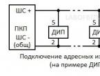
The designation of the heat detector in the diagram, as well as other components, is as follows:
- ShS- alarm loop
- IP- thermal fire detector,
- YPRES- manual fire detector
- DIP- fire smoke detector.
Conditional graphic designation of an automatic heat detector according to the requirements of regulatory documentation -  .
.
Norms and features of installation / connection of thermal sensors are regulated with water of the rules of the fire protection system 5.13.130.2009 with the latest changes from 20.06.2011
From table 13.5, the distance between the thermal spot devices, as well as between them and the wall, becomes known (do not forget about the exceptions indicated in paragraph 13.3.7).
Source: SP5.13.130.2009.
It is easy to guess that the area covered by the sensor depends on the height of the room. At the same time, many install two devices in each room in case one sensor fails.
The distance from one to the other should be limited to half the recommended. But this works with point non-address sensors. Analog addressable ones do not need duplication, since they have a completely different principle of operation.
- When locating sensors in rooms, it is necessary to take into account the peculiarities of the distribution of combustion products in them.
- It is inefficient to install heat sensors in “dead” zones, where the hot air will reach the last place, and the fire extinguisher will work too late.
- So, when laying a thermal cable of a linear heat detector, it is not necessary to do this 15-20 cm from the corners along the ceiling and walls.
- Do not forget about hoods, air conditioners - place the device at least a meter away from them.
Physical laws give rise to the principles that underlie the installation of fire detectors:
- a flat ceiling is protected along a circle lying in a horizontal surface;
- you need to take into account the distance from the ceilings of the room.
Faults and solutions
First of all, we read about them in the instruction manual in a specially dedicated section. The description indicates what may not work and what method will help fix the problem.
The classic reasons are unprofessional installation and factory defects. A detected marriage leads to a warranty period, which averages from 18 to 36 months, but sometimes 12 months.
- Experienced engineers also point out a false fire alarm in the event of a repair, when dust gets into the device and it goes off.
- Sometimes insects also serve as a cause for unjustified anxiety. Rubbing with alcohol and blowing helps.
- Loops can periodically notify of a fire with twisted wires, where the contact is unstable.
- No one has canceled electromagnetic interference from devices, so they must be taken into account. Seasonal changes, acoustic fluctuations and aggressive environments also affect malfunctions.
- False alarms often do not indicate the high sensitivity of the detectors, but low quality. Experts also warn that all cheap developments lose their level of sensitivity over time. And here only a replacement will help.
To solve most problems with a malfunction, checking the connections, the correct location of the detectors and the normal operation of the contact connections will help.
Also, high-quality components of the detectors will help to prevent the non-detection of a fire.
Manufacturers and popular models
Fire detectors are produced by Russian and foreign manufacturers. Among them
- oldest Japanese company Hochiki,
- most popular Siemens, which was joined by the Swiss manufacturer Cerberus.
- Fire detectors from a British company have proven themselves well Appolo.
- Also well known System Sensor, whose products are produced in 8 largest countries - from the USA to Russia.
In our country, specializes in fire heat detectors
- company "Argus-Spectrum" located on the basis of the scientific and industrial complex in St. Petersburg.
- Kitstroyservis is one of the leaders in domestic developments.
- Magneto-Contact produces sensors based on sealed contacts,
- a wide range of products from Siberian Arsenal”,
- research and production enterprise " Spetsinformatika-SI”.
- Also, private enterprise offers its products “ Arton" And " Spetsavtomatika”.
Prices
The simplest maximum fire-fighting thermal appliances are domestic, their price is from 40 rubles to 150. 
- Additional options, for example, a memory for a triggered device, a light and / or remote indicator, an increase in their number entails a doubling in price, a spread of 270 rubles. and up to 600.
- Maximum differential sensors can be purchased for a price of 500 rubles. up to 900.
- One of the best selling models Aurora TN (IP 101-78-A1), its price is an average of 700 rubles.
- The most popular explosion-proof detector model due to its affordability IP 101-3A-A3R will cost 200 rubles on average, although most stores offer explosion-proof devices from 800 to 1,000 rubles.
Foreign addressable maximum differential devices
- cost from 1000 rubles per piece and higher.
- Among the address-analog maximum-differential - bestseller model S2000 IP-03, She is standing from 500 to 800 rubles, but in general, the run-up of addressable detectors reaches 2,000 and even higher.
- thermal sensors - thermal cables - depending on the characteristics (cable resistance, maximum allowable length, current voltage, etc.), they are sold on average from 300 to 700 rubles.
Conclusion
Information about the principles of operation, design features, types and types of thermal fire detectors will help you choose the most suitable model in a balanced way and without unnecessary financial costs. Installation rules and regulations are not that complicated, and if you take them responsibly, you can prevent many malfunctions. And it is best to carry out the installation under the strict guidance of experienced electricians.