Non-destructive testing laboratory - building inspection, structural inspection, structural inspection, supervision, design, engineer-construction company. Technologies and devices for non-destructive testing of concrete
Non-destructive testing of concrete is the control of material parameters, in which the structure remains suitable for use. The construction is not subjected to complete destruction, and the main part of the tests are the calculations of the necessary parameters, taking into account the data obtained. The purpose of this study is to timely detect structural defects that have arisen in the process of construction or operation.
Types and methods of non-destructive testing:
- Optic. It is carried out with registration of parameters of optical radiation, which interacts with concrete.
- Thermal imaging inspection. Changes in the thermal fields of a building caused by defects are checked.
- Acoustic emission. The parameters of elastic waves in the range below 20 kHz that occur or are excited in the object are recorded.
- . Similar to acoustic emission, but in this case, the analysis of the parameters of elastic waves in the range above 20 kHz. Allows you to determine the characteristics of the material not only on the surface, but also in the body of the structure. Also, with its help, you can find out the quality of concreting, depth, conduct flaw detection.
- X-ray. The essence of the method is to analyze the parameters of ionizing radiation during its interaction with concrete.
- Magnetic. The analysis of the interaction of the magnetic field with the studied material is carried out.
- Eddy current. The point is in the analysis of the interaction of an external electromagnetic field with the electromagnetic field of eddy currents induced in an object.
- Leak detection and capillary. Common name - penetration control method. It is based on the penetration of substances into the cavity of the structure. Shows the presence of defects, including through.
Local destruction methods
The most accurate, widespread concrete control methods. There are several options: separation with chipping (using anchor devices or metal disks), cleaving the ribs of the structure.
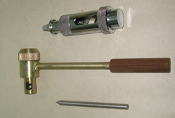 One of the easiest, fastest, and therefore often used options. Concrete test non-destructive method The shock pulse is carried out as follows: a rod of a given strength is inserted into a Kashkarov hammer or similar device, after which the device is beaten on the surface of the structure and the dimensions of the prints on the rod and concrete are determined. You can also use an electronic device for testing, which after impact determines the strength of the material automatically.
Both devices - both mechanical and electronic - are compact and do not need long preparation before use. Thanks to this, tests are carried out quickly.
Using the shock impulse method, it is possible to determine not only strength, but also the class of concrete. In addition, this method allows you to find out the strength at different angles to the surface.
Elastic rebound method
 Tests are carried out using a Schmidt sclerometer or other similar device. The device is a hammer with a scale and a system of springs. The device is designed so that it freely bounces off the surface after impact. In this case, the scale fixes the path of the striker with a reverse bounce.
The basis of the method is the measurement of the surface hardness of concrete. For this purpose, it fits perfectly, because it allows you to get fairly accurate data and is carried out using easy-to-use instruments.
Nondestructive Testing Laboratory
In our laboratory for non-destructive testing of concrete, you can order testing using any of the methods listed above, as well as a comprehensive study. Services are available to both legal entities and individuals.
Turning to us, you will receive:
- Professional consultation. Often one non-destructive testing concrete is not enough to get accurate and as complete information as possible. We will recommend methods that are suitable in your case, if necessary, we will select a set of works.
- Accurate results. The excellent technical equipment of the laboratory and the high qualification of specialists are confirmed by approvals and certificates.
- Data that all market participants will reckon with. Standard is an accredited laboratory with an impeccable reputation. The results obtained by us and compiled do not cause doubts either among the employees of regulatory bodies or among the heads of companies.
How to order?
Contact us - we will answer all your questions, conduct tests at a convenient time for you and provide a report.
Building structures based on a mixture of binder, sand and aggregate need testing for reliability and safety. However, such studies should not cause interruption in the operation of the test object, therefore it is carried out by a non-destructive method. This allows you to reduce costs, reduce the complexity and eliminate local damage.
Direct control methods
These methods are necessary for the formation of calibration dependences and their subsequent adjustment for indirect methods carried out on the same sections of the structure. The technology may be applicable for surveys at various stages of the construction of buildings, as well as for the operation and reconstruction of finished facilities.
Chipping
A similar operation is carried out in accordance with state standards, which reflects the basic information about the method of conducting. The results are not affected by the surface condition.
For research, three types of anchor devices are used.
- Work rod equipped with an anchor head.
- A device with a expandable cone and grooved segmented cheeks.
- A device with a hollow expandable cone, which has a special rod for fixing the device in one position.

Note! When choosing the type of fixture and the penetration depth of the anchor, one should take into account the estimated strength of the composition and dimensions of the aggregate, which is reflected in the table below.
| Drying conditions for the mixture | Type of device used | Anchor immersion depth in mm | Estimated Strength in MPa | Coefficient value | |
| Light composition | Heavy solution | ||||
| Heat treatment | 1 | 4835 | <50>50 | 1,2 | 1,32,6 |
| 2 | 4830 | <50>50 | 1,0 | 1,12,7 | |
| 3 | 35 | <50 | — | 1,8 | |
| Natural hardening | 1 | 4835 | <50>50 | 1,2 | 1,12,4 |
| 2 | 4830 | <50>50 | 1,0 | 0,92,5 | |
| 3 | 35 | <50 | — | 1,5 | |
In monolithic structures, the concrete strength is tested by a non-destructive method, which involves tearing off with chipping, in three areas at once. When adjusting calibration dependencies, three indirect tests are carried out together with this method.
Rib chipping
This method involves cutting off the ribs of the test structure. It is primarily used to control linear segments such as crossbars, columns, piles, lintels and support beams. The operation does not require additional preparation, however, in the presence of a protective layer with a thickness of less than 20 mm, the method may not be applicable.
Detachment of metal discs
Another event that allows the non-destructive method of concrete control to be implemented is not widely used in our country, which is associated with a limited temperature regime. Another negative factor is the need to make a furrow with a drill, and this reduces the productivity of the study.
The method itself involves removing the registration voltage, which is required for the local destruction of the hardened composition when the separation of the steel disk. When determining the strength qualities, the applied force and the surface projection area are taken into account.
Indirect control methods
Similar studies are carried out when it is necessary to assess the value of strength characteristics, using them as one of several factors that give an idea of \u200b\u200bthe technical condition of the structure. The result obtained is not allowed to be used unless a particular calibration dependence () has been determined.
Ultrasound testing
A widespread method of testing concrete non-destructive method, involving the use of ultrasonic waves. During the operation, a relationship is established between the oscillation velocity and the density of the hardened mixture.
A variety of factors can influence addiction.

- Aggregate fraction and its amount in solution.
- The selected method of preparation of the composition.
- Degree of compaction and voltage.
- A change in binder consumption by more than 30 percent.
Addition! Ultrasonic surveys provide the ability to perform mass testing of virtually any design an unlimited number of times. The main disadvantage lies in the margin of error.
Elastic rebound
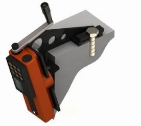
Non-destructive testing of concrete strength by this method allows us to establish the relationship between compressive strength and elasticity of the material. In the study, the metal firing pin of the main device after the impact is moved away by a certain distance, which is an indicator of the strength properties of the structure.
During testing, the fixture is fixed so that the steel element is in close contact with the concrete surface, for which special screws are used. After fastening, the pendulum is mounted horizontally. In this case, it snaps directly with the trigger.
Putting the device perpendicular to the plane, pull the trigger. The hammer is cocked automatically, after which it is independently released and makes a blow under the action of a special spring. The metal element bounces at some distance, which is measured by a special scale.
The instrument of the KISI system, which has a rather complex structure, is used as the main test tool. The strength of the hardened mixture can be determined on the basis of the device data after 6-7 tests according to a special schedule.
Impulse impulse
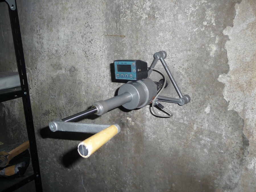
Thanks to this research method, it is possible to fix the impact energy released at the moment of contact of the striker with a concrete structure. A positive point is the fact that non-destructive testing devices for concrete, working on the basis of a shock pulse, have compact dimensions. However, their price is quite high.
Plastic deformation
During the operation, the size of the trace left on the concrete surface with a steel element is measured. The method is considered somewhat outdated, but due to the low cost of equipment, it continues to be actively used in the construction environment. After the strike, the remaining prints are measured.
Devices for determining the strength of this type are based on the indentation of the rod directly into the plane by static pressure of the desired strength or conventional impact. The main devices used are pendulum, hammer and spring products.
The following are the conditions for the operation.
- Tests should be carried out on a site whose area ranges from 100 to 400 square meters. cm.
- During this operation, at least five measurements should be made with high accuracy.
- Impact force should have a perpendicular direction relative to the test plane.
- To determine the strength characteristics, a smooth surface is required, which is achieved by molding in a metal formwork.
Important! If the concrete strength is measured by a non-destructive method using hammer-type devices, then the samples should be installed on a perfectly flat base.
Comparative characteristic on an example
A well made of monolithic reinforced concrete is taken as an object. Its depth is 8 m, and its radius is 12 m. The side surfaces were filled with grips that divide the structure into 7 tiers in height.
The research results are presented in the table below.
| Tier | Indirect research methods | ||||||
| Ultrasonic | Shock impulse | Elastic rebound | Press test | ||||
| Wed value in m / s | Percentage ratio | Wed value in MPa | Percentage ratio | Wed value in y units | Percentage ratio | Wed value in MPa | |
| 1 | 4058 | 3,9 | 41,9 | 23,4 | 46,2 | 7,8 | 41,6 |
| 2 | 4082 | 4,6 | 24,4 | 40,2 | 43,7 | 7,6 | 35,0 |
| 3 | 4533 | 5,2 | 49,6 | 28,7 | 49,7 | 9,9 | 36,5 |
| 4 | 4300 | 3,9 | 38,1 | 36,3 | 46,6 | 8,3 | 40,1 |
| 5 | 4094 | 4,1 | 38,2 | 28,5 | 48,2 | 8,5 | 42,1 |
| 6 | 4453 | 3,6 | 45,5 | 41,6 | 47,6 | 7,6 | 39,3 |
| 7 | 3836 | 4,5 | 42,8 | 26,5 | 44,6 | 7,3 | 30,6 |
| Wed value V | ≈4,26 | ≈32,2 | ≈8,14 | ||||
Conclusion! From the table below it becomes clear that the minimum error in the research is characteristic of the ultrasonic method. The spread during the shock pulse test is maximum.
Instrumentless testing
The above studies were conducted using special devices, but if necessary, simple tests can be done with your own hands. Accurate information about the strength properties cannot be obtained, but it is quite realistic to determine the class of concrete.
First, the necessary tool is prepared: a chisel and a hammer, the weight of which varies between 400-800 g. An impact-cutting device is installed perpendicular to the surface.
It uses medium-power strikes, which will be followed by analysis.

- A barely noticeable imprint may indicate that the hardened mixture belongs to class B25 and higher.
- Highly visible marks on the surface of the structure usually remain when using concrete B15.
- Significant recesses and the presence of crumbs allow us to attribute the composition used to class B10.
- If the tip of the tool went into the plane to a depth of more than 1 cm, then concrete B5 was probably used for work.
Attention! Verification in this way can be done in a few minutes without any equipment. After that, there will already be an idea of \u200b\u200bwhat strength the hardened composition has.
State standard
Non-destructive methods for controlling the strength of concrete are regulated in accordance with GOST 22690-88, the items of which apply to light and heavy mixtures. However, it reflects only mechanical methods that do not include ultrasound. Their limit values \u200b\u200bare presented in the table.

Concrete work
- To form structures on the basis of the building mixture, wooden or metal formwork is made, which is able to give the desired shape to the material.
- To improve the quality characteristics, a mesh of steel reinforcement, fastened with welding or wire, is placed in the composition. Typically, the cell size ranges from 10 to 20 centimeters.
- If it is necessary to separate some part from the structure, then reinforced concrete cutting with diamond wheels is used. A similar operation can be carried out using water to avoid heavy dusting.
- The filling of the solution is carried out, as a rule, at positive temperatures. However, in the presence of special equipment for warming up, it is permissible to carry out work with negative thermometer values.
- To create ventilation inside a concrete structure (for example, for a foundation or attic) diamond drilling of holes in concrete is carried out.
- It is allowed to load the finished structure only after the final solidification of the mixture, that is, after 28 days.
![]()
In conclusion
The presented instruction allows you to get an idea about the verification of the strength properties of concrete structures, not only using special equipment, but also using improvised means. However, an independent method will make it possible to make only a preliminary assessment of the characteristics ().
More detailed information about the control can be obtained after watching the video in this article.
Determination of compressive strength made by calculation according to the formulas and graphs specified in, as well as using the graphs attached by the manufacturers of devices. Both in GOST and in the manufacturer’s graphs, calibration dependencies between the strength parameter itself and its indirect value are indicated.
Obtaining readings by instruments is carried out in the study of the building structure itself. In addition, tests obtained from the design of samples can be carried out. This is necessary to obtain strength readings in hard-to-reach areas, as well as at negative ambient temperatures. The samples obtained are poured with concrete mortar with a strength of at least 50% of the sample strength. For this, it is convenient to use standard forms according to. The order of placement of samples after filling is shown in Fig. 1.
Fig. 1. 1 - concrete sample; 2 - the most convenient for testing side of the sample; 3 - the solution in which the sample is fixed
As mentioned above, non-destructive testing devices have their own calibration curves or basic settings for studies of heavy concrete of medium grades.
To obtain indications of structural strength, it is possible to use technologies of elastic rebound, shock impulse, or plastic deformation. Obtaining the exact value is carried out using the calibration dependence determined for concrete, which differs with the composition tested, the solidification conditions, age or humidity. Clarification of values \u200b\u200bis carried out according to the method specified in pr. 9..
For determining ultrasonic strength indicators calibration and adjustment of the data obtained by the device according to GOST 17624 and GOST 24332 are necessary. Table 1 shows the data of the distances between the test points and the number of tests for various non-destructive testing methods.
Table 1
|
Namemethod |
The number of tests on the site |
Distance between test sites, mm |
The distance from the edge of the structure to the test site, mm |
Construction thickness |
|
Elastic rebound |
||||
|
Shock impulse |
||||
|
Plastic deformation |
||||
|
Rib chipping |
||||
|
2 disc diameters |
||||
|
Chipping |
5 digging depths |
Double anchor depth |
Elastic test rebound
The method for determining the structural strength requires a distance between the points of application of force and the reinforcement of at least 50 mm. The test process consists of the following steps:
- Placing the device on the surface of the structure so that the direction of the force goes at an angle of 90 °.
- Relative to the horizontal, the device is positioned in the same way as when testing samples to determine calibration. If a different installation point is selected, corrections must be made in accordance with the recommendations of the device manufacturer.
- An indirect characteristic is determined.
- The indirect characteristic is calculated on the construction site.
Determination of compressive strength by Sclerometer - Schmidt Type N

Sclerometer Is a device for measuring the strength of concrete and concrete mortar with elastic rebound techniques as required. The measurement boundaries for this technique are from 5 to 50 MPa (for grades M50 - M500).
The device consists of a percussion mechanism and an indicator arrow placed in a cylindrical body. Measurement is carried out by actuating the shock mechanism. The value of the rebound of the striker is fixed by an arrow. The obtained impact hardness index is converted into the strength index using the graph attached to the sclerometer. The schedule is based on a comparison of the readings of destructive measurements on cubic samples by crushing in the press and tests with a sclerometer.

Chipping
For testing on cleavage technique anchor insertion points should be located in the zones of minimum stress from the loads acting on the structure or the minimum compression force of prestressed reinforcement.
The measurement process consists of the following steps:
- If the flap anchor was not laid before concreting, then a hole is drilled or a hole is punched with a size and depth corresponding to the requirements of the device used.
- An anchor device is mounted in a hole or hole.
- The device is connected to the embedded anchor.
- The device is driven, starting with a minimum load on the gap with a subsequent increase at a speed of from 1.5 to 3 kN / s.
- After separation, the indicators of the applied force and the minimum with the maximum depth of chipping are recorded. Depth measurement accuracy should be at least 1 mm.
This way is determined accurate indicator of concrete strength except as follows:
- if the difference between the maximum and minimum values \u200b\u200bof cleavage between the boundaries of destruction and the surface differ by more than 2 times;
- the difference between the depths of tearing and embedding differs by more than 5%.
With the above factors, the use of totals is allowed only for an approximate assessment.
ATTACHMENT
In case of application according to anchor devices, concrete strength indicator R, MPa is determined by the formula for the transfer of destructive force (P) obtained during testing to compressive strength:
m1 - coefficient of accounting for the maximum size of a large aggregate. It is assumed equal to 1 with a particle size of up to 50 mm, 1.1 - with a particle size of 50 mm .;
m2 is the coefficient of conversion to compressive strength, depending on the brand of concrete and the circumstances of its hardening.
When measuring heavy concrete with a strength of 10 MPa and expanded clay concrete with a strength of 5 to 40 MPa, the indicator m2 is assumed equal in accordance with table 2
table 2
|
Hardening condition for concrete |
Type of anchor device |
Estimated concrete strength, MPa |
Embedment depth, mm |
Coefficient valuem 2 for concrete |
|
|
heavy |
lung |
||||
|
Natural |
|||||
|
Heat treatment |
|||||
The device for measuring the concrete strength indicator by the separation method with chipping “Onyx-OS”

For measurements, a section of a flat surface measuring 200x200 mm is required. A hole with a depth of 55x10-3 m is strictly perpendicular to the surface of the structure with a deviation of not more than 1 degree is punched or drilled (with a Schliemburg or an electromechanical tool) in the center of the site.
The measurement process consists of the following steps:
- An anchor consisting of a cone and three segments is laid in the hole corresponding to the above parameters.
- The thrust nut is twisted with the force necessary to prevent the anchor from slipping.
- The support of the device is twisted completely into the working cylinder.
- The pump screw is set to the upper position.
- The device is connected to the traction nut.
- The support is screwed into close contact with the surface of the structure.
- An anchor device breaks out by rotating the pump handle.
- The destructive force is determined by visual method according to the pressure readings on the manometer. Accuracy should be up to 2.5 kgf / cm2.
It is very important that the anchor structure does not slip during testing. The measurement results are not taken into account when slipping more than 5x10⁻³ m. Re-use of the hole is not permissible since this can lead to incorrect results.
Determination of the depth of cleavage is determined using two rulers. The first is located edge on the test surface, the second is determined by the depth.
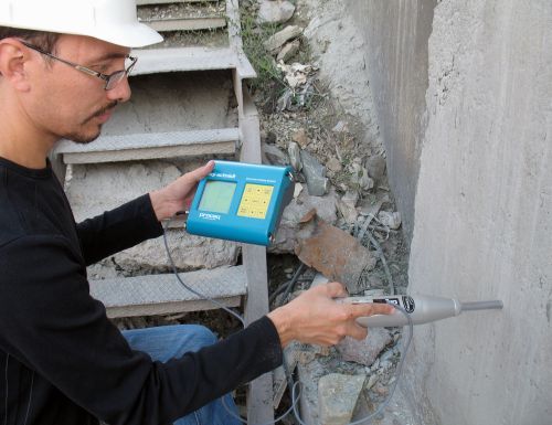
Ultrasonic method for determining the strength of concrete
The strength characteristics of concrete are determined by the ultrasonic method based on the existing relationships between the speed of propagation of sound waves and the strength of the material. For this, special calibration dependencies are used between the ultrasound speed and strength, or between the propagation time and strength. The choice of dependence is based on ultrasonic scanning technology.
For ultrasound examination pass-through or surface sounding techniques are used. For prefabricated building structures, such as columns, beams, beams, etc., an end-to-end ultrasonic scanning technique is applied with the direction of the waves in the transverse direction. If there are difficulties with through scanning due to design features, as well as for wall panels, ribbed flat panels and other flat building structures, surface scanning is used. The sounding base is set as on the samples when installing the calibration dependence.
Between the surfaces of the device and building structures, a dense acoustic contact is provided using technical petroleum jelly and other viscous materials. The definition of a calibration dependence depends on the choice of sounding technique. When through, the dependence of strength on the speed of propagation of the sound wave is determined, with surface - the dependence of strength on the time of its passage. In surface scanning, it is possible to use the “speed-strength” ratio using the transition coefficient (pr. 3.).
The propagation time of a sound wave through a material is determined when it is directed at a right angle to the seal at a distance of 30 mm or more from the edge of the investigated surface of the building structure. It is also mandatory to direct the wave at a right angle to the reinforcement incorporated in the structure when its concentration in the research zone is not more than 5% of the volume of reinforced concrete. Perhaps the direction of the wave parallel to the reinforcement at a distance from the reinforcement is not less than 60% of the base length.
Pulsar 1.2

Fig. 2. Appearance of the device Pulsar-1.2: 1 - input of the receiver; 2 - emitter output
The Pulsar device (Fig. 2.) includes an electronic unit and ultrasonic transducers. The latter can be separate or combined into a single unit. The electronic unit is equipped with a keyboard and display, there are connectors for connecting a surface scan unit or individual ultrasound transducers for end-to-end scanning. The device is also equipped with a USB connector for connecting to information and computing systems. Access to autonomous power sources is through the cover at the bottom.
The functions of the device are based on measuring the time to overcome the ultrasonic pulse through the material being studied from the emitter to the receiver. The speed (V) of the passage of the wave is determined by the formula:
N is the distance from the emitter to the receiver;
t is the wave propagation time.
The most accurate indicator is determined as the result of data processing after six measurements. From 1 to 10 measurements are carried out with the determination of the average value, as well as taking into account two coefficients - variation and heterogeneity.
The speed of passage of an ultrasonic wave through the test concrete depends on the indicators:
- density and elasticity;
- the presence or absence of defects (cracks and voids), on which the strength properties and quality of the material depend.
Based on this, scanning ultrasound elements of building structures it is possible to obtain information about:
- strength indicators;
- monolithic structure;
- parameters of density and elasticity moduli;
- the presence / absence of flaws, as well as their location and configuration;
- a-waveform.
It is possible to conduct studies using grease and through dry contact, see fig. 3.
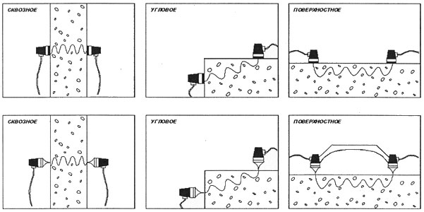
Fig. 3. Sounding options
The device "Pulsar" fixes and visualizes ultrasonic pulses; it is equipped with digital and analog filters for eliminating interference. When operating in the oscilloscope mode, it is possible to visually observe the signals on the display, the operator can independently set the cursor to the position of the first entry check mark, change the measurement path increase, shift the time axis to study the first arrival pulses and the envelope.
Designing the obtained structural strength data by non-destructive testing methods
The results of the tests are recorded in a journal which indicates:
- the name of the building structure, the number of the party under investigation;
- the type of strength studied and its necessary parameter;
- concrete parameters;
- the name of the research methodology used, the model of the device used and its serial number;
- the average indirect indicator of strength and the proper value of the strength of the material;
- data on the use of correction factors;
- total strength indicators;
- data on the persons who conducted the tests and their signature, date of the test.
To determine the strength by ultrasonic method, it is necessary to use the form specified in pr. No. 8-9, GOST 17624-87 "CONCRETE. ULTRASONIC METHOD FOR DETERMINING STRENGTH "
Impulse-shock method for determining the strength of concrete

Concrete branding through technology impulse study produced by IPS-MG4.01 in accordance with the requirements.
Technical characteristics of the device IPS-MG4.01:
The principle of operation of shock-pulse equipment consists in checking the hardness and elasticity of a building structure using a shock pulse. To do this, a series of strokes (15 pcs.) Is carried out in one place on the surface of the building structure. Further, the device recalculates the obtained values \u200b\u200band determines the average indicator. Based on the obtained indicator, the actual concrete grade of the building structure is determined.
The main advantage of this technique is its simplicity and the ability to work in difficult conditions. However, it should be borne in mind that the data obtained are not enough for an expert assessment of the strength of concrete. For this, other control techniques are necessary, in particular, separation with chipping.
Before you get acquainted with such a concept as determining the strength by a non-destructive method, you need to fully understand what concrete is.
The most stringent requirements for concrete, which is used in the construction of bridges and strategically important facilities.
Concrete is a building stone material of artificial origin, which is obtained by hardening a properly selected compacted mixture of binders (cement, sand, gravel, water, and other aggregates). To increase the ability to withstand aggressive environments and enhance the strength properties use special additives. A mixture of all these components before it hardens is called a mixture.
The stone foundation is formed by sand and gravel. After adding water to the mixture, a cement paste is formed, which fills the gaps between the sand and gravel, enveloping them, and initially serves as a lubricant for aggregates, by which the mixture becomes mobile (fluid). In the process of hardening the grain, aggregates are bonded to form an artificial monolithic stone called concrete. When combined with steel reinforcement, the resulting structure is called reinforced concrete.
Unbrakable control

The components must be clean, free from impurities, and the water must be fresh.
This is a type of control of parameters and properties, which should not lead to a violation of the suitability of concrete for subsequent operation or use. Non-destructive testing is of particular importance in the construction and operation of critical components, structures or products.
When determining strength indicators using non-destructive testing methods, it is very important to understand that the results of all these methods are based on indirect characteristics. It is impossible to give preference to one or another method, they all have their advantages, disadvantages and limitations of application. For a more accurate determination, the mobile road laboratory should be equipped with non-destructive testing devices, including all control methods. The initial stage of the building’s existence is characterized by ongoing monitoring of the linear dimensions of the project and the absence of significant deviations from building codes.
To do this, use:
- all kinds of lines;
- calipers;
- roulettes;
- staples;
- calipers;
- microscopes
- probes and other special equipment.
Protection circuit
Deviations of structures from permissible horizontal and vertical indicators are usually measured:
- level;
- theodolite;
- calibration ruler.
In already constructed buildings, the strength characteristics of individual structural elements are usually determined by two methods.
- In one of them, the structure is loaded up to the moment of its destruction, thus determining the maximum bearing capacity. But such a method is very expensive and impractical from an economic point of view.
- Non-destructive methods, in which the use of special instruments for assessing the state of structures is implied, are much more attractive and more convenient. Such cases involve the processing of the obtained results and values \u200b\u200busing special computer programs that allow obtaining the values \u200b\u200bof the final characteristics with sufficient accuracy.
The permissible error during testing is the most significant factor in determining methods and means of control and measurement. At the same time, ease in processing results and ease of work are very important.
Non-destructive methods are based on indirect indicators:
- imprint;
- stress leading to partial (local) structural damage;
- energy spent on impact.
Details of the most commonly used non-destructive testing methods for concrete and other building materials will be described later.
Local destruction options
Such non-destructive methods for controlling strength are the most accurate, since they allow the use of a universal calibration dependence, which implies a change in only two parameters:
![]()
Concrete Type Chart
- the degree of fineness of the aggregate, which is assumed to be 1.0 if the fineness is less than 5.0 cm and 1.1 if the fineness is greater than 5.0 cm;
- type (light or heavy).
The method of tearing with a chip and the method of chipping a structural rib is characterized by recording the forces required to chip a part of the structural rib or local destruction of concrete along the course of pulling out the anchor structure from it.
The method of separation with a chip is the only method of non-destructive testing of strength for which calibration standards are provided for by standards. This method is most accurate, however, due to the large labor costs that are necessary for drilling holes and installing anchors. The main disadvantage of this method is the impossibility of application in structures with dense reinforcement and thin walls.
In structures with dense reinforcement, when the method of tearing with a chip and the method of chipping the ribs cannot be used, the strength of concrete can be determined by tearing off metal disks. It is quite accurate, but much less time-consuming in comparison with the method of separation with a chip. The disadvantages of the method include the requirement for gluing discs several hours before the start of the test. The time depends on the conditions and glue used.
The method of cleaving a structural rib is usually used to determine the strength of linear elements (columns, piles, beams, crossbars, lintels). To start the tests, preliminary preparatory work is required. Moreover, with violations of the protective layer and the protective layer having a thickness of less than 2.0 cm, the method is unacceptable.
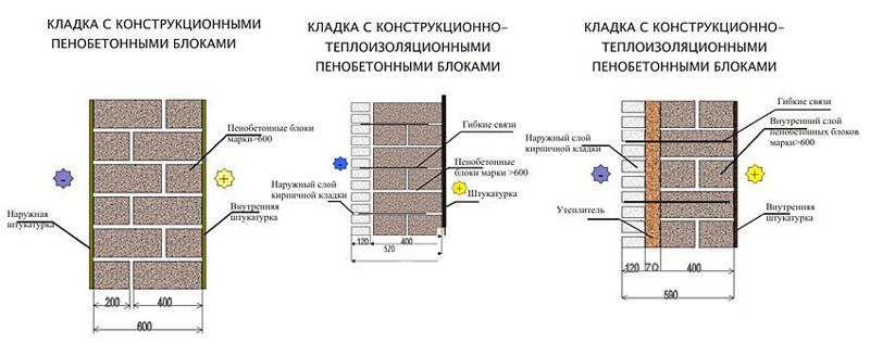
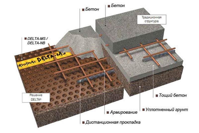
The scheme of masonry made of foam concrete.
The method of tearing metal disks is characterized by recording the stresses necessary for local concrete destruction during the separation of the steel disk from its surface, equal to the efforts spent on separation, divided by the projection area of \u200b\u200bthe torn concrete surface to the plane of the disk. In modern life, this method is used very rarely.
The disadvantages of methods for determining strength by local destruction include:
- high labor input;
- inability to use in areas with dense reinforcement;
- the need to determine the axes of the reinforcement and the depths of their location;
- partial damage to the integral structure.
Shock impact methods
One of the most common methods of non-destructive testing of concrete strength is the shock pulse method.
In this method, the impact energy is recorded, which occurs at the moment when the striker hits the concrete surface.
The equipment used in this method is characterized by a relatively low weight and occupied space. And to determine the strength of concrete by the method of shock pulse is quite simple. All results are expressed in the same units as the compressive strength. According to the measurements, they also determine the class of concrete, measure strength at different angles to the plane of the object, transfer the results to a computer.
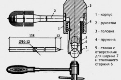
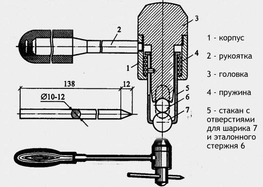
The Koshkarov hammer is one of the methods for determining the strength of concrete.
Impact pulses are called low-energy waves obtained as a result of impact, which are generated by bearings, rolling due to pressure changes and collisions in the rolling zone during the operation of the bearings and propagate in the bearing elements, the bearing assembly and parts in contact with it.
Using the shock pulse method has the following main functions:
- early warnings about changes in the lubrication conditions of bearings to carry out work to replace the lubricant according to its actual condition;
- early warnings about changes in the operation of bearings due to the influence of various external factors for the implementation of measures to eliminate them on time and on time (for example, imbalance, overload, etc.);
- early warning of defects that occur in the bearings for timely replacement;
- minimizing equipment downtime
- minimizing the risks associated with equipment failures. Ensuring reliable performance.
The method of elastic rebound is the amount of backward rebound obtained as a result of the impact of the striker with a concrete surface. Schmidt sclerometer and its various analogues are the most common instruments for testing this method. The measurement of the surface hardness of a concrete structure is the basis of the elastic rebound method and the plastic deformation method.
Initially, the hardness of metals was determined by the elastic rebound method. The tests are carried out using devices called sclerometers, which are spring-type hammers with stamps in the form of a sphere. The hammer spring system does not interfere with the free rebound of the hammer after impact with a concrete surface or with a steel plate pressed against concrete. A scale with an arrow on the device fixes the path of the drummer during his bounce back. The force of impact with a hammer should be no less than 0.75 Nm, the radius of the spherical stamp at the end of the hammer should be at least 5 mm. After every 500 strokes, the device is calibrated (checked).
In the course of the test, after each collision, a measurement is made according to the scale of the device (accuracy should be one division). The result is recorded in a special logbook. The requirements for the preparation of test sites (location, number of impact sites and experiments for constructing calibration curves) are identical to the requirements of the plastic deformation method.
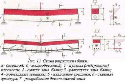
The destruction scheme of a concrete beam.
The method of plastic deformation is characterized by measuring the imprint remaining on the concrete after hitting a steel ball on it. This method of measuring strength is already outdated, but it is still used today, since testing does not require expensive equipment.
The most widespread for conducting such tests was the Kashkarov hammer. The principle of operation is relatively simple. The hammer is equipped with a special removable metal rod, which has a certain already known strength. Such a hammer is struck on a concrete surface. Then, the impressions resulting from the impact on the core and concrete are measured using an angular scale. The strength of concrete is calculated by the ratio of the size of the prints.
Devices for determining the strength of concrete by the method of plastic deformations are based on the effect of pressing a stamp into a concrete surface upon impact or static pressure of a certain force. Their use is limited. Percussion devices are hand or spring hammers with a stamp in the form of a sphere (ball) and pendulum devices with a stamp in the form of a ball or disk.
Instrument stamps must be:
- hardness not less than HRC60;
- the roughness Ra is less than 0.32 microns. Maximum stamp wear - up to 5 microns;
- with a ball diameter of not less than 10 mm;
- impact force should be at least 125 N-cm;
- disk thickness not less than 1 mm.
Ultrasonic method
This method is based on measuring the speed of ultrasonic waves. The tests are carried out using the method of end-to-end ultrasonic sounding (the sensors are located on opposite sides of the sample to be tested) and the surface sounding method (the sensors are placed on one side of the sample).
The method of end-to-end sounding with ultrasound allows you to determine the strength not only in the concrete layer near the surface, but also in the body of the whole structure, in contrast to other non-destructive methods of strength control.
Devices based on ultrasonic waves are used not only to determine the strength characteristics of concrete, but also for quality control, flaw detection and depth measurement. Ultrasound propagates in concrete at a speed reaching 4500 m / s - this is quite a lot.
The calibration dependence of the speed of propagation of ultrasonic waves and the compressive strength of an object is determined individually for each concrete composition. This is due to the fact that when determining the strength, the use of several calibration concrete dependencies of unknown or other compositions will lead to possible errors.
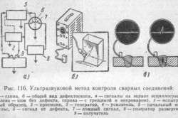
Ultrasonic weld inspection method.
The dependence "speed of ultrasonic waves - concrete strength" is due to the influence of the following factors, the changes of which should be taken into account when using the ultrasonic method for determining the strength:
- granularity of the aggregate and its composition;
- fluctuations in cement flow rate of more than 30%;
- concrete manufacturing method;
- concrete compaction;
- concrete condition (stressed).
An ultrasonic method for determining the strength is available for mass repeated testing of structures having any shape and allows constant monitoring of the increase or decrease in strength indicators. The disadvantages of the method include the error obtained during the transition of acoustic characteristics in strength. It is impossible to control the quality of high-strength concrete with ultrasonic devices, that is, the strength spectrum of concrete is limited to grades from B7.5 to B35 or from 10 to 40 MPa (GOST 17624-87).
Destructive methods
Any construction organization independently chooses control methods, but according to the requirements of SNiPs in force today, destructive control must be carried out necessarily.
There are several ways to meet these requirements:
- concrete strength is determined on specially manufactured samples. This method is used in the construction of prefabricated reinforced concrete structures and for controlling the output of ready-mixed concrete at a construction site;
- strength measurements are obtained by sawing or cutting samples directly from the structure. Samples are taken at specific locations. In this case, depending on the stress state, a decrease in the bearing capacity is taken into account. Places of sampling should be indicated in the design documentation or determined by the designers in the course of the work;
- samples, the so-called “cubes”, made directly at the construction site in accordance with specific technological regulations, are sent to the laboratory for testing. However, obtaining concrete cubes (their hardening, storage) is significantly different from the actual conduct of concrete work (degree of compaction and hardening time of mixtures). These differences significantly reduce the accuracy of the results obtained by this method.
Paperwork
All results obtained during the tests are recorded in a special journal, which should contain the following data:
- design name and batch number;
- type of measured strength and its permissible value;
- type of concrete;
- test method (method), device, including serial number;
- the average indicator of the characteristic of indirect strength and the corresponding indicator of concrete strength;
- correction factors used;
- test results for assessing the strength of concrete;
- Name, date and signature of the person performing the test.
Self measurement

Table of methods for establishing the strength of concrete.
Laboratory methods of non-destructive testing of concrete strength are a rather expensive and not always affordable pleasure. It is possible to independently conduct a test for the strength of the concrete structure.
For successful testing, you must have:
- a hammer having a weight of 0.40-0.80 kg;
- chisel.
A chisel is attached to the surface of the concrete, and a medium-impact blow is applied to it with a hammer. Then measure the damage caused by the concrete layer, determining its class:
- B25 - the chisel has left little risk;
- B15 - B25 - the chisel left a more noticeable notch;
- B10 - the chisel penetrated the concrete structure to a depth of less than 5 mm;
- B5 - the chisel cut through concrete more than 10 mm.
Classification or labeling of concrete by strength is the main quality indicator of concrete mix. According to these indicators, it is possible to determine the average strength of a concrete structure. For example, the average strength of concrete of the M400 (B30) grade is 393 kgf / cm ?.
The approximate concrete strength Rb, accumulated on day 28, can be calculated using the basic law of concrete strength - the Bolomey-Skramtaev formula. To do this, you need to know exactly the brand of cement used (Rc) and the ratio of water to cement (C / B). The average value of coefficient A is taken equal to 0.6 (provided that the aggregates are of normal quality).
Rb \u003d Rc * A * (C / B - 0.5)
In this case, the strength gained by concrete in time is calculated by the formula:
n \u003d Strength according to brand * (log (n) / log (28)),
where n is not less than 3 days.
Approximately 30% of the brand strength of concrete is achieved on the 3rd day, 60 - 80% - on the 7th day, the ultimate strength (100%) of the concrete acquires on the 28th day. Of course, an increase in strength can occur over time, but this happens very slowly.
Fresh concrete requires care until it reaches 70% strength or until another time for dismantling the formwork (SNiP 3.03.01-87).
Self-determination of concrete strength is inherently simple and inexpensive. However, during the construction of important and especially important facilities, it is necessary to seek help from specialized laboratories.
During the quality control of monolithic structures, in the process of building construction, a concrete strength check is performed, in which, according to GOST R 53231 - 2008, the following is performed:
- Strength monitoring of monolithic structures is carried out in two stages: at an intermediate age (when removing the bearing formwork; loading structures until they reach design strength).
Upon reaching the design age of the concrete structure of 28 days. If 90% of the design strength of concrete is reached, when tested at an intermediate age, concrete testing at design age may not be performed.
- According to GOST R 53231 - 2008, concrete tests are carried out according to schemes B, C, D with control at an intermediate and design age.
The strength of concrete is determined by the results of testing control samples of concrete according to GOST 10180 and GOST 28570 or non-destructive methods according to GOST 17624 and GOST 22690.
- To determine the strength of concrete intended for the construction of monolithic structures at a construction site, as part of the incoming quality control of products, laboratory tests are carried out of control samples of cubes of ready-mixed concrete. For a more accurate assessment of concrete strength, it is recommended to use together two methods for determining the strength of control samples (according to Scheme B) and non-destructive testing of concrete strength in areas of constructed structures (according to Scheme C), or control samples (cores) are drilled from the structure.
Laboratory strength control
To conduct tests on control samples, at least 2 samples are taken from sample batches from each batch of concrete and at least 1 sample per day. A series of control samples is prepared from each sample. The number of samples in each series according to GOST 10180-90 should be from 2 to 6 pieces, the allowable size of the samples is 100x100, 150x150, 200x200. The selected concrete mix is \u200b\u200bpoured into attorney forms corresponding to GOST 22685-89. After a day, control samples should be removed from the molds and harden under the conditions of construction of a building structure.
Testing procedure for non-destructive quality control in structures. Field tests of concrete in structures
Unbrakable control The quality of concrete structures is carried out in each type of monolithic structures with the number of test sections - at least three tests for each gripper for flat structures (walls, floors, foundation slabs) and at least six test sections for linear vertical structures (columns, pylons). At least one section per 4m of length, or three sections per grip, for linear horizontal structures (beams, crossbars).
When determining the strength of monolithic structures at an intermediate age, at least one structure of each type from a batch of concrete laid during the day, or part of the structure if it is concreted for more than a day, is controlled.
Number of tests in each section it is determined depending on the non-destructive testing method for concrete strength, either mechanical non-destructive testing methods according to GOST 22690, or the ultrasonic method for determining concrete strength, according to GOST 17624.
When controlling the strength of concrete by the ultrasonic method, according to GOST 17624, at least two measurements are made at each controlled area, with surface sounding or one, with through sounding.
When monitoring the strength of concrete mechanical non-destructive methods the number of measurements is determined according to table 3 of GOST 22690, depending on the method used:
Table 3 mm
The total number of sites when measuring the strength of concrete by a non-destructive method should be at least 20, the number of sites when measuring one structure should be at least 6.
METHODS FOR DETERMINING CONCRETE STRENGTH IN NON-DESTRUCTIVE TESTING
To measure the strength of concrete, the strength measurement methods used in GOST 22690 are used. CONCRETE DETERMINATION OF STRENGTH BY MECHANICAL METHODS OF NON-DESTRUCTIVE TESTING and GOST 17524 Concrete. at ultrasonic method for determining the strength.
Chipping Method
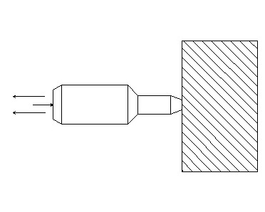
The tearing method implements loading of concrete with a uniformly increasing tearing force of an anchor of a certain shape fixed in concrete at a given depth hn until a concrete fragment is torn off or to a given control load.
Determination of strength by the shock pulse method in accordance with GOST 22690-88
The method is based on the use of the dependence of the magnitude (height) of the rebound of a conditionally elastic body, when it hits a concrete surface, on the strength of this concrete. As a result of the impact of the moving mass on the concrete surface, the initial kinetic energy is redistributed in such a way that one part is absorbed by the concrete during the manifestation of plastic deformations, and the other part is transferred to the shock mass as a reactive force, which is converted into the kinetic energy of the rebound. In order for the initial impact energy to be distributed in this way, the mass of concrete must be infinitely large compared to the mass of the impactor, which should eliminate the energy consumption for moving the concrete mass. Testing equipment: Beton Pro CONDTROL Strength Meter.
Ultrasonic Strength Method
Method for measuring strength based on the requirements of GOST 17624-87. The essence of the method is to determine the strength of concrete on the basis of the calibration dependence established according to the test data of the cubes on the press.


