Selection of the RES cooling system. Choosing a cooling method Calculating costs at the product production stage
Explanatory note for the diploma project: 18 figures, 20 tables, 24 sources, 3 sheets of drawings in A1 format.
Object of research: regulation of cooling of computer systems.
Subject of research: cooling systems for computer systems.
The first section discusses the general principles of cooling and the operation of various types and types of cooling of computer systems.
The second section pays special attention to various types of cooling systems from the point of view of their improvement; the optimal choice of cooling system is made according to various criteria.
In the third section, a feasibility study of the development object was carried out, a technical and economic analysis of various cooling systems was carried out.
In the fourth section, calculations of heating, ventilation, natural and artificial lighting were carried out, and the obtained values were compared with the standard ones.
FAN, WATER COOLING, AIR COOLING, COMPUTER SYSTEM, NITROGEN COOLING, PASSIVE COOLING, PELTIER ELEMENT
Introduction
1.3 Hard drive cooling
2.1.1 Fan design
2.2 Passive cooling
2.4 Cooling economy
4. Labor protection
4.1.2 Lighting
4.1.3 Microclimate parameters
4.1.4 Noise and vibration
4.3 Working hours
4.4 Illumination calculation
4.5 Ventilation calculation
4.6 Calculation of noise level
List of links
List of symbols, symbols, units, abbreviations and terms
ADC – analog-to-digital converter
CMOS – complementary logic based on metal-oxide-semiconductor transistors
OLS – least squares method
MPS – microprocessor system
CPU - central processing unit
PWM – pulse width modulation
Introduction
The topic of the thesis is “Adjusting the cooling of computer systems,” which will be the subject of research.
The purpose of the work is to explore the cooling control of computer systems and the scope of application.
The objectives of the study are to identify and select the most effective means of cooling computer systems.
The work is divided into stages:
1. Study of the principles of cooling (types and types).
2. Research of new progressive cooling systems.
3. Comparison of technical and economic indicators of various types of cooling.
The relevance of this topic is very high, because... The overall performance of the entire computer system – its productivity and durability – depends on the performance of the cooling properties of the system.
The high performance of modern computers comes at a price: they consume enormous power, which is dissipated as heat. The main parts of the computer - the central processor, the graphics processor - require their own cooling systems; Gone are the days when these chips were content with a small heatsink. The new system unit is equipped with several fans: at least one in the power supply, one cools the processor, a serious video card is equipped with its own fan. Several fans are installed in the computer case; there are even motherboards with active cooling of the chipset chips. Some modern hard drives also reach noticeable temperatures.
Most computers are equipped with cooling based on the principle of minimizing cost: one or two noisy case fans are installed, the processor is equipped with a standard cooling system. The cooling is sufficient, cheap, but very noisy.
There is another way out - complex technical solutions: liquid (usually water) cooling, freon cooling, a special aluminum computer case that dissipates heat over its entire surface (essentially works like a radiator). For some tasks it is necessary to use such solutions: for example, for a recording studio, where the computer must be completely silent. For ordinary home and office use, such specialized systems are too expensive: their prices start from hundreds of dollars and above. Such options are very exotic today.
1. Cooling of computer systems
1.1 Principles of cooling (types and types)
Cold air is heavy and therefore goes down, while hot air, on the contrary, is light and therefore tends to rise. This simple theorem plays a key role in organizing proper cooling. Therefore, the air must be provided with an entrance at least in the lower front part of the system unit and an exit in its upper rear part. Moreover, it is not at all necessary to set the fan to blow. If the system is not very hot, a simple hole at the air entry point will be sufficient.
Let's calculate the required power of the case cooling system. For calculations we use the following formula:
Q = 1.76*P/(Ti - To), (1.1)
where P is the total thermal power of the computer system;
Ti is the air temperature inside the system case;
To is the temperature of fresh air sucked into the system unit from the environment;
Q is the performance (flow rate) of the case cooling system.
The total thermal power (P) is found by summing the thermal powers of all components. These include the processor, motherboard, RAM, expansion cards, hard drives, ROM/RW drives, power supply. In general, what is installed inside the system unit.
For the temperature in the system (Ti), we need to take the temperature we want inside the system unit. For example - 35 o C.
For To, take the maximum temperature that generally occurs during the hottest time of the year in our climate zone. Let's take 25 o C.
When all the necessary data has been obtained, we substitute it into the formula. For example, if P=300 W, then the calculations will look like this:
Q = 1.76*300/(35-25) = 52.8 CFM
That is, on average, the total number of revolutions of all case fans, including the fan in the power supply unit, should be at least 53 CFM. If the propellers spin more slowly, this can lead to burnout of any component of the system and its failure.
Also in cooling theory there is such a thing as system impedance. It expresses the resistance provided to the air flow moving inside the housing. This resistance can be provided by everything that is not this flow: expansion boards, cables and wires, case fasteners, etc. That is why it is advisable to tie all the wiring together with clamps and place it in some corner of the air so that it does not become an obstacle to the air flow.
Now that we have decided on the total power of the case cooling system, let’s think about exactly how many fans we need and where to place them. We remember that one fan, but installed wisely, will bring more benefits than two, but installed illiterately. If, when calculating P, we received no more than 115 W, then unless absolutely necessary there is no point in installing additional case fans; one fan in the power supply will be enough. If the system generates more than 115 W of heat, you will need to add fans to the case to preserve its life for many years. At a minimum, you need to install one “exhaust” fan on the rear wall of the system unit in addition to the fan in the power supply.
Fans, as you know, tend to make noise. If the noise is particularly annoying, you can resort to this method of solving the problem: instead of one fast and noisy one, install two slower and low-speed ones. Share the load, so to speak. For example, instead of one 80 mm with 3000 rpm. screw two of the same (or even 120 mm) at 1500 revolutions each. It is preferable to replace one of a smaller diameter with two larger diameters because a large impeller will move more cubic meters of air per minute than small blades. In some cases, you can even limit yourself to simply replacing one smaller fan with one larger one.
Cooling can be passive or active.
A passive is simply a heatsink resting on the surface of the die and attached to a "socket" or "slot". It has not been used for a long time to cool most CPUs; it is sometimes installed on the GPU and is actively used to cool RAM modules, video memory and chipsets. This cooling is based on natural air convection. The radiator should preferably be copper (dissipates heat better than aluminum) and needle-shaped (without pointed ends of the needles). The main thing is the total surface area. The larger it is, the more efficient the heat removal. The radiator base must be smooth, otherwise contact with the chip (and, consequently, heat transfer) will be disrupted. All radiators have such a characteristic as temperature resistance. It shows how much the processor temperature will change when its power consumption increases by 1 Watt. The lower this resistance, the better. Radiators are mounted to the chip either with a special mount (to the processor socket) or glued with hot-melt adhesive (to memory chips, chipset). In the first case, you must first apply a thin layer of thermal paste to the surface of the processor (to create a thermal interface). The most common thermal pastes are KPT-8 and AlSil.
Active cooling. Can be air, water, cryogenic and nitrogen.
Figure 1.1 - Air cooling
Air. It is also called aerogenic. This is passive cooling + cooler, that is, a radiator with a fan mounted on top. A cooler is, as you know, a fan installed on a chip, for example, on a processor or graphics core. Absolutely all fans have a lot of characteristics by which their professional suitability can be assessed:
Fan dimensions. Expressed as height x width x height. For example, 80x80x20. All values are expressed in mm (millimeters). There is a difference between the size of the fan housing (size of the cooler, written as length x width) and the size of the actual square in which the circumference of the impeller is inscribed (fan size, length x width). The size of the cooler in all respects is a couple of millimeters higher than the size of the fan. Typically, the dimensions of a cooler are not 80x80x20, but simply 80x80 (eighty by eighty). Coolers come in sizes 40x40, 50x50, 60x60, 70x70, 80x80 and 120x120. The most common are 40x40, 80x80 and 120x120.
Bearing type. The fan impeller rotates either by a sleeve bearing or a rolling bearing (ball). Both have their advantages and disadvantages.
Sliding bearing. Its structure is as follows: a rotor is inserted into a bushing lubricated with grease. A fan with such a bearing is simply overgrown with disadvantages, which include: low service life compared to a rolling bearing, which is also shortened when a fan with such a bearing is located near temperatures above 50 o C; impeller imbalance - when the rotor rubs against the bushing, the latter wears out not evenly (that is, not along all the circles), but only on two sides, as a result of which the cross section over time becomes an oval rather than a circle. Because of this, rotor beating occurs and, as a result, noise. In addition, over time, lubricant begins to leak out of the gap between the bushing and the rotor, which clearly does not help stop the runout. Coolers with a plain bearing have only two advantages: they are very cheap compared to their ball counterparts and operate quieter until the bushing wears out or the lubricant runs out. The latter can be solved by disassembling the motor and replacing the lubricant.
Friction bearing. The device is somewhat different: instead of lubricant, balls are placed between the bushing and the rotor, along which the rotor rotates. The sleeve is closed on both sides with special rings, which prevents the balls from spilling out. The disadvantages of such coolers are the opposite of the advantages of sleeve coolers - ball is more expensive and noisier than sleeve. The advantages are resistance to high temperatures transmitted by the radiator and greater durability.
There is also a combined solution:
A fan that rotates both sleeve and ball bearings. In this case, the second increases durability and reduces noise levels. There are also fans with a plain bearing, but their rotor has a thread cut into it, which, when rotating, prevents the lubricant from flowing to the bottom, so that it continuously circulates inside the bushing.
Number of revolutions per minute. Fan impeller rotation speed. This parameter is measured in RPM (Rotations Per Minute) and the higher this value, the better. As a rule, it ranges from 1500 to... it’s difficult to say how much, since the rpm value is constantly increasing by manufacturers. The faster the fan spins, the louder it makes. Here you have to choose: either speed, cold and noise, or silence and high temperatures. The operation of any fan can be slowed down by reducing the voltage supplied to the motor. This can be done by connecting to a 7 or even 5 V channel instead of 12 V, or by soldering a 10-70 Ohm resistor into the fan power wire break. But if the voltage is too low (below 6 V), the fan may simply not have enough power, and it will not start spinning and will not provide proper cooling.
The volume of air driven in one minute. Also called efficiency. Measured in CFM (Cubic Feet per Minute). The higher the CFM, the louder the noise the fan makes.
Noise level. Measured in dB. Depends on the value of the two previous parameters. Noise can be mechanical or aerodynamic. Mechanical noise is affected by RPM and CFM values. Aerodynamic depends on the bend angle of the impeller. The higher it is, the stronger the air beats against the blades and the louder the rumble.
Power connection method. PC Plug (directly to the power supply) or Molex (to the motherboard).
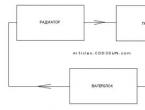
The next type of cooling is water cooling. Consists of a water block, radiator, water or refrigerant tank, pump and connecting hoses. A water block with two connectors (fittings) for the inlet and outlet hoses is installed on the processor. Cooled water (coolant) is pumped to the radiator through the inlet hose from the pump, passes through it and through the outlet hose, being heated by the heat of the processor, moves to the second radiator (on which the fan is installed) to release the heat taken from the CPU.

Figure 1.2 - Water cooling
After this, the water flows back into the pump, and the pumping cycle repeats. Water CO has only two parameters: tank volume and pump power. The first is measured in l (liters), and power is measured in l/hour. The higher the power, the higher the noise the pump makes. Water cooling has an advantage over air cooling, since the coolant used has a much higher heat capacity than air, and therefore more effectively removes heat from the heating elements. But, in spite of everything, water cooling is not very common due to its high cost relative to air cooling and the danger of a short circuit in case of depressurization and leakage.
Cryogenic cooling. CO, which cools the chip using a special gas - freon. It consists of a compressor, condenser, filter, capillary, evaporator and suction tube. It works as follows: gaseous freon enters the compressor and is pumped there. The gas then enters the condenser under pressure, where it turns into liquid and releases energy in thermal form. This energy is dissipated by the capacitor into the environment. Next, freon, already a liquid, flows into the filter, where it is cleaned of random debris that can get into the capillary and, clogging it, disable the cooling system. Through the capillary, liquid freon enters the evaporator, where, under the influence of the heat transferred from the evaporator, it begins to boil, actively absorbing the thermal energy received from the processor, and through the suction tube it enters back into the compressor and the cycle repeats.

Figure 1.3 - Cryogenic cooling
It is not common due to its high cost and the need to replenish freon, since it evaporates over time and has to be added to the cooling system. It is also effective during overclocking, as it is capable of creating sub-zero temperatures.
Nitrogen cooling. The entire cooling system consists of a medium-sized container filled with liquid nitrogen. There is no need to bring anything anywhere or take it away. When heated by the processor, liquid nitrogen evaporates and, reaching the “ceiling” of the container, becomes liquid and again falls to the bottom and evaporates again. Nitrogen cooling, like freon cooling, can provide sub-zero temperatures (approximately -196 o C). The inconvenience is that liquid nitrogen, like freon, has the ability to boil away, and you have to add it in considerable quantities. In addition, nitrogen cooling is very expensive.

Figure 1.4 - Nitrogen cooling
The operating principle of the Peltier element is based on the operation of p- and n-type semiconductors.
Another cooling device consisting of two semiconductor wafers. When an electric current is passed through them, one plate begins to freeze, and the other, on the contrary, radiates heat. Moreover, the temperature gap between the temperatures of the two plates is always the same. The Peltier element is used as follows: the “freezing” side is attached to the processor.

Figure 1.5 - Peltier element
The danger of using it is due to the fact that if the element is installed incorrectly, there is a possibility of condensation forming, which will lead to equipment failure. So when using the Peltier element you should be extremely careful.
1.2 Cooling processors and video cards
The CPU and GPU are the most powerful sources of heat inside a modern computer. Many different designs of cooling systems have been developed for these components; the variety of design solutions is amazing.
As a rule, a significant limiting factor when choosing a cooler for a processor and video card is cost: highly efficient and quiet cooling systems are very expensive. From what was said in the section on cooling principles (section 1.1), it follows that it is better to use cooling systems with the largest possible radiators, preferably copper ones. Due to the high cost of copper, a combined scheme is often used: a copper core pressed into an aluminum radiator; Copper helps distribute heat more efficiently. It is better to use low-speed cooling system fans: they are quieter. To maintain acceptable performance, large fans are used (up to x120 mm). This is, for example, what the Zalman CNPS7700-AlCu processor cooler looks like.
Often, to build a large radiator, heat pipes are used - hermetically sealed and specially arranged metal tubes (usually copper). They transfer heat very efficiently from one end to the other: thus, even the outermost fins of a large radiator work effectively in cooling. This is how the popular Scythe Ninja cooler works, for example.
To cool modern high-performance GPUs, the same methods are used: large radiators, copper cores of cooling systems or all-copper radiators, heat pipes to transfer heat to additional radiators.
The recommendations for selection here are the same: use slow and large fans, and the largest possible radiators. This is, for example, what the popular cooling systems for video cards Zalman VF700 and Zalman VF900 look like.
Typically, fans of video card cooling systems only mixed the air inside the system unit, which is not very effective in terms of cooling the entire computer.
Only very recently, cooling systems that remove hot air outside the case began to be used to cool video cards: the first were Arctic Cooling Silencer and, with a similar design, IceQ from the HIS brand.
Similar cooling systems are installed on the most powerful modern video cards (nVidia GeForce 8800, ATI x1800XT and older). This design is often more justified, from the point of view of the correct organization of air flows inside the computer case, than traditional designs.
1.3 Hard drive cooling
Like any other component of a computer, the hard drive tends to heat up during operation. And although the issue of cooling this component is not particularly acute, if there is severe overheating, the service life of the drive is significantly reduced. In addition, many users are faced with the problem of HDD noise and vibration. And while there is a huge selection of appropriate coolers on the market to organize cooling of the processor and video card with a minimum noise level, there is no list of cooling systems of this class for hard drives.
A typical HDD cooler is a plate with a fan (or two) that is screwed onto the bottom of the drive. These coolers are the cheapest and most efficient. Of course, the noise from additional fans in the system unit increases.
To combat the above problem, as well as for additional cooling of hard drives, Scythe produces two CO models - Himuro and Quite Drive. It can rightly be said that these devices stand out from similar systems. Their design is similar - a radiator housing, inside of which the drive is installed. The housing dampens vibration and noise, and in terms of the combination of these characteristics, these models are perhaps the most successful on the market. And if Quite Drive has already managed to win consumer recognition, then Himuro is a relatively new model.
If you measure the heating during hard work, then the temperature of a modern HDD can reach 50-60 degrees Celsius. For the electrical part, this, of course, is not very scary, although its service life is also reduced - modern microcircuits have a clear temperature regime. And during design, the manufacturer has to think about heat removal from the elements (especially from the motor driver). But the plates located in the hermetic block are very sensitive to elevated temperatures. This is expressed as a direct dependence of the number of operating hours between failures of the operating mode. If these modes do not correspond to the nominal ones, then the service life may decrease several times. We risk losing not only the device, but also the data stored on it. Moreover, elevated temperatures lead to the appearance of “bad” sectors on the plates, and information recovery in such cases may become impossible.
The most important thing is the optimal operating temperature of the hard drive. Looking at Table 1.1, everything will immediately become clear.
Table 1.1 – Hard drive performance depending on temperature
| Temperature, °C |
Failure rate |
Temperature coefficient of reduction in time between failures |
Adjusted MTBF |
1.4 Cooling the system unit
Modern standards for the design of computer cases, among other things, also regulate the method of constructing a cooling system. Starting with systems based on Intel Pentium II, the production of which began in 1997, the technology of cooling a computer with a through air flow directed from the front wall of the case to the back is being introduced (additional cooling air is sucked in through the left wall) (Figure 1.11).

At least one fan is installed in the computer's power supply (many modern models have two fans, which can significantly reduce the rotation speed of each of them, and, therefore, noise during operation). Additional fans can be installed anywhere inside the computer case to increase air flow. It is imperative to follow the rule: on the front and left side walls, air is pumped into the body, on the rear wall, hot air is thrown out. You also need to make sure that the flow of hot air from the back wall of the computer does not go directly into the air intake on the left wall of the computer (this happens at certain positions of the system unit relative to the walls of the room and furniture). Which fans to install depends primarily on the availability of appropriate fasteners in the case walls. Fan noise is mainly determined by its rotation speed, so it is recommended to use slow (quiet) fan models. With equal installation dimensions and rotation speeds, the fans on the rear wall of the case are subjectively noisier than the front ones: firstly, they are located further from the user, and secondly, there are almost transparent grilles at the back of the case, while in front there are various decorative elements. Often noise is created due to the air flow bending around the elements of the front panel: if the transferred volume of air flow exceeds a certain limit, vortex turbulent flows are formed on the front panel of the computer case, which create a characteristic noise (it resembles the hiss of a vacuum cleaner, but much quieter).
2. Adjusting the cooling of computer systems
2.1 Air cooling of computer systems
Fans are used to move air in cooling systems.
2.1.1 Fan design
The fan consists of a housing (usually in the form of a frame), an electric motor and an impeller secured with bearings on the same axis as the motor (Figure 2.1).

Figure 2.1 – Fan (disassembled)
The reliability of the fan depends on the type of bearings installed. Manufacturers state this typical MTBF (years based on 24/7 operation) (Table 2.1).
Taking into account the obsolescence of computer equipment (for home and office use this is 2-3 years), fans with ball bearings can be considered “eternal”: their service life is no less than the typical service life of a computer. For more serious applications, where the computer must work around the clock for many years, it is worth choosing more reliable fans.
Table 2.1 – Dependence of fan operation on bearing brand
Many have encountered old fans in which the sliding bearings have exhausted their service life: the impeller shaft rattles and vibrates during operation, producing a characteristic growling sound. In principle, such a bearing can be repaired by lubricating it with solid lubricant, but how many would agree to repair a fan that costs only a couple of dollars?
2.1.2 Fan characteristics
Fans vary in size and thickness: usually in computers there are standard sizes of 40x40x10 mm, for cooling video cards and hard drive pockets, as well as 80x80x25, 92x92x25, 120x120x25 mm for case cooling. Fans also differ in the type and design of the installed electric motors: they consume different currents and provide different impeller rotation speeds. The performance depends on the size of the fan and the speed of rotation of the impeller blades: the created static pressure and the maximum volume of transported air.
The volume of air a fan moves (flow rate) is measured in cubic meters per minute or cubic feet per minute. The fan performance indicated in the specifications is measured at zero pressure: the fan operates in open space. Inside the computer case, a fan blows into a system unit of a certain size, therefore it creates excess pressure in the serviced volume. Naturally, volumetric productivity will be approximately inversely proportional to the pressure created. The specific type of flow characteristic depends on the shape of the impeller used and other parameters of the specific model. For example, the corresponding graph for the GlacialTech SilentBlade GT80252BDL fan (Figure 2.2).

Figure 2.2 – SilentBlade GT80252BDL fan performance
A general view of the SilentBlade II GT80252-BDLA1 fan is shown in Figure 2.3, and its characteristics are below.

Figure 2.3 - General view of the SilentBlade II GT80252-BDLA1 fan
Specifications of the SilentBlade II GT80252-BDLA1 fan
PC case cooling fan
Low noise level
Supply voltage 12 V
2 x Rolling bearing
Rotation speed 1700 (± 10%) rpm.
Airflow 26.3 CFM
Dimensions 80 x 80 x 25 mm
Power connector 3-pin + 4-pin connector
Black color
A simple conclusion follows from this: the more intense the fans in the back of the computer case work, the more air can be pumped through the entire system, and the more efficient the cooling will be.
The noise level generated by a fan during operation depends on its various characteristics. It's easy to establish a relationship between performance and fan noise. On the website of a large manufacturer of popular Titan cooling systems, in the case fans section, we see: many fans of the same size are equipped with different electric motors, which are designed for different rotation speeds. Since the same impeller is used, we obtain the data we are interested in: the characteristics of the same fan at different rotation speeds. We compile a table for the three most common sizes: thickness 25 mm, 80 × 80 × 25 mm, 92 × 92 × 25 mm and 120 × 120 × 25 mm (Table 2.2).
Table 2.2 – Noise level of various Titan fans

The most popular types of fans are highlighted in bold.
Having calculated the coefficient of proportionality of air flow and noise level to revolutions, we see an almost complete coincidence. To clear our conscience, we count deviations from the average: less than 5%. Thus, we received three linear dependencies, 5 points each. We consider the hypothesis confirmed.
The volumetric performance of the fan is proportional to the number of revolutions of the impeller, the same is true for the noise level.
Using the obtained hypothesis, we can extrapolate the results obtained using the least squares method (OLS): in the table, these values are highlighted in italics. It must be remembered, however, that the scope of this model is limited. The studied dependence is linear in a certain range of rotation speeds; it is logical to assume that the linear nature of the dependence will remain in some vicinity of this range; but at very high and very low speeds the picture can change significantly.
Now let's look at a line of fans from another manufacturer: GlacialTech SilentBlade 80x80x25 mm, 92x92x25 mm and 120x120x25 mm. Let's make a similar table 2.3.
Table 2.3 - Noise level of various GlacialTech fans

Calculated data is highlighted in italic font.
The general view of fans of this series is shown in Figure 2.4.

Figure 2.4 – General view of GlacialTech fans
As mentioned above, at fan speed values that differ significantly from those studied, the linear model may be incorrect. The values obtained by extrapolation should be understood as a rough estimate.
Let us pay attention to two circumstances. Firstly, GlacialTech fans work slower, and secondly, they are more efficient. Obviously, this is the result of using an impeller with a more complex blade shape: even at the same speed, the GlacialTech fan moves more air than the Titan (see the growth column). And the noise level at the same speed is approximately equal: the proportion is maintained even for fans from different manufacturers with different impeller shapes.
You need to understand that the actual noise characteristics of a fan depend on its technical design, the pressure created, the volume of pumped air, and the type and shape of obstacles in the path of air flow; that is, on the type of computer case. Since a wide variety of cases are used, it is impossible to directly apply the quantitative characteristics of fans measured under ideal conditions - they can only be compared with each other for different fan models.
2.1.3 Monitoring and control of fans
Most modern motherboards allow you to control the rotation speed of fans connected to some three- or four-pin connectors. Moreover, some of the connectors support software control of the rotation speed of the connected fan. Not all connectors located on the board provide such capabilities: for example, on the popular Asus A8N-E board there are five connectors for powering fans, only three of them support rotation speed control (CPU, CHIP, CHA1), and only one supports fan speed control (CPU); The Asus P5B motherboard has four connectors, all four support rotation speed control, rotation speed control has two channels: CPU, CASE1/2 (the speed of two case fans changes synchronously). The number of connectors with the ability to control or control the rotation speed does not depend on the chipset or south bridge used, but on the specific model of the motherboard: models from different manufacturers may vary in this regard. Often, board developers deliberately deprive cheaper models of the ability to control fan speed. For example, the motherboard for Intel Pentiun 4 processors Asus P4P800 SE is capable of adjusting the speed of the processor cooler, but its cheaper version Asus P4P800-X is not. In this case, you can use special devices that are capable of controlling the speed of several fans (and, usually, provide for the connection of a number of temperature sensors) - more and more of them are appearing on the modern market.
You can control fan speed values using BIOS Setup. As a rule, if the motherboard supports changing the fan speed, here in BIOS Setup you can configure the parameters of the speed control algorithm. The set of parameters varies for different motherboards; Typically, the algorithm uses the readings of thermal sensors built into the processor and motherboard. There are a number of programs for various operating systems that allow you to control and regulate fan speeds, as well as monitor the temperature of various components inside the computer. Manufacturers of some motherboards complete their products with proprietary programs for Windows: Asus PC Probe, MSI CoreCenter, Abit µGuru, Gigabyte EasyTune, Foxconn SuperStep, etc. Several universal programs are widespread, among them: Hmonitor (shareware, $20-30), MotherBoard Monitor (distributed free of charge, not updated since 2004). The most popular program of this class is SpeedFan (Figure 2.5).

Figure 2.5 - SpeedFan program
2.2 Passive cooling
Passive cooling systems are usually called those that do not contain fans. Individual computer components can be satisfied with passive cooling, provided that their radiators are placed in sufficient air flow created by “foreign” fans: for example, the chipset chip is often cooled by a large radiator located near the installation site of the processor cooler. Passive cooling systems for video cards are also popular, for example, Zalman ZM80D-HP (Figure 2.6).

Figure 2.6 – Passive cooling of video cards
Obviously, the more radiators one fan has to blow through, the greater the flow resistance it needs to overcome; Thus, when increasing the number of radiators, it is often necessary to increase the rotation speed of the impeller. It is more efficient to use many low-speed, large-diameter fans, and it is preferable to avoid passive cooling systems. Despite the fact that passive radiators for processors, video cards with passive cooling, and even fanless power supplies (FSP Zen) are available, an attempt to assemble a computer without any fans from all these components will certainly lead to constant overheating. Because a modern high-performance computer dissipates too much heat to be cooled by passive systems alone. Due to the low thermal conductivity of air, it is difficult to organize effective passive cooling for the entire computer, unless you turn the entire computer case into a radiator, as is done in the Zalman TNN 500A (Figure 2.7).
Perhaps completely passive cooling will be sufficient for low-power specialized computers (for accessing the Internet, listening to music and watching videos, etc.)

Figure 2.7 – Zalman TNN 500A computer case-radiator
2.3 Water cooling of computer systems
This approach to cooling computer systems is the most common - a system is assembled, often consisting of a dozen fans, all with an optimized impeller and hydrodynamic bearings. The textolite of printed circuit boards can hardly withstand kilograms of copper of highly efficient radiators pierced with heat pipes. The result of all these fancy improvements drops in direct proportion to the power of the system, since the temperature inside the case rises rapidly with increasing power, and in top configurations, pumping air through the case still causes significant noise. A deadlock situation arises when each component of the system is quite silent, say 18-20 dB, but put together they produce 30-35 dB of even more unpleasant noise due to the different spectrum and resulting interference. It is worth noting the increased difficulty of cleaning dust from such a design. If a standard system is easy to clean once every six months with a regular vacuum cleaner, then all these thin-finned designs of modern coolers are very difficult to clean. For some reason, manufacturers do not pay enough attention to the problem of dust in cases; only some cases are equipped with very ineffective dust filters. Meanwhile, dust crushed by fans not only harms cooling by settling on the surface of radiators, but is also very harmful to human health, since it is not retained by the bronchi and is removed from the lungs for a very long time. Some sources believe that the harm from fine dust is comparable to the harm from passive smoking. CD/DVD and FDD drives suffer greatly from dust; I've even seen a card reader clogged with dust to the point of being completely unusable.
Water cooling systems are deservedly popular. The principle of their operation is based on coolant circulation. Computer components that need cooling heat the water, and the water, in turn, is cooled in the radiator. In this case, the radiator can be located outside the case, and even be passive (Figure 2.8).

Figure 2.8 - One of the most advanced water cooling systems
The disadvantage of water cooling is:
1. noise - the higher the power, the higher the noise emitted by the pump.
2. despite everything, water cooling is not very common due to its high cost relative to air cooling and the danger of a short circuit in case of depressurization and leakage.
2.4 Cooling economy
A typical home or office computer, in the absence of resource-intensive tasks, is usually only 10% loaded - anyone can verify this by launching the Windows Task Manager and observing the CPU (Central Processing Unit) load chronology. Thus, with the old approach, about 90% of the processor time was wasted: the CPU was busy executing unnecessary commands. Newer operating systems (Windows 2000 and later) act more wisely in a similar situation: using the HLT (Halt, stop) command, the processor completely stops for a short time - this, obviously, allows you to reduce energy consumption and processor temperature in the absence of resource-intensive tasks.
Experienced computer geeks can recall a number of programs for “software processor cooling”: when running under Windows 95/98/ME, they stopped the processor using HLT, instead of repeating meaningless NOPs, thereby reducing the temperature of the processor in the absence of computing tasks. Accordingly, the use of such programs under Windows 2000 and newer operating systems makes no sense.
Modern processors consume so much energy (which means they dissipate it in the form of heat, that is, they heat up) that developers have created additional technical measures to combat possible overheating, as well as means that increase the efficiency of saving mechanisms when the computer is idle.
2.4.1 Processor thermal protection
To protect the processor from overheating and failure, so-called thermal throttling is used (usually not translated: throttling). The essence of this mechanism is simple: if the processor temperature exceeds the permissible temperature, the processor is forced to stop with the HLT command so that the crystal has the opportunity to cool down. In early implementations of this mechanism, through BIOS Setup it was possible to configure how much time the processor would be idle (CPU Throttling Duty Cycle parameter: xx%); new implementations “slow down” the processor automatically until the temperature of the crystal drops to an acceptable level. Of course, the user is interested in ensuring that the processor does not cool down (literally!), but does useful work - for this it is necessary to use a fairly effective cooling system. You can check whether the processor thermal protection mechanism (throttling) is activated using special utilities, for example ThrottleWatch (Figure 2.9).

Figure 2.9 – ThrottleWatch utility
In this case, the processor is cooled unsatisfactorily: as soon as the processor load increases, the throttling mechanism is triggered.
2.4.2 Minimizing energy consumption
Almost all modern processors support special technologies to reduce energy consumption (and, accordingly, heating). Different manufacturers call such technologies differently, for example: Enhanced Intel SpeedStep Technology (EIST), AMD Cool’n’Quiet (CnQ, C&Q) - but they essentially work the same way. When the computer is idle and the processor is not loaded with computing tasks, the clock speed and supply voltage of the processor are reduced. Both reduce the processor's power consumption, which in turn reduces heat dissipation. As soon as the processor load increases, the full speed of the processor is automatically restored: the operation of such a power saving scheme is completely transparent to the user and the programs being launched. To enable such a system you need:
Enable the use of supported technology in BIOS Setup;
Install the appropriate drivers in the operating system you are using (usually a processor driver);
In the Windows Control Panel, in the Power Management section, on the Power Schemes tab, select the Minimal Power Management scheme from the list.
You can check that the processor frequency is changing using any program that displays the processor clock frequency: from specialized ones like CPU-Z, right up to the Windows Control Panel, System section (Figure 2.10).

Figure 2.10 - Windows control panels
AMD Cool"n"Quiet in action: the current processor frequency (994 MHz) is less than the nominal one (1.8 GHz).
Often, motherboard manufacturers additionally equip their products with visual programs that clearly demonstrate the operation of the mechanism for changing the frequency and voltage of the processor, for example, Asus Cool&Quiet (Figure 2.11).

Figure 2.11 – Asus Cool&Quiet panel
The processor frequency varies from maximum (in the presence of a computing load) to a certain minimum (in the absence of CPU load).
2.4.3 RMClock utility
During the development of a set of programs for comprehensive testing of RightMark CPU processors, the RMClock (RightMark CPU Clock/Power Utility) utility was created: it is designed to monitor, configure and manage the energy-saving capabilities of modern processors. The utility supports all modern processors and a variety of energy management systems (frequency, voltage...). The program allows you to monitor the occurrence of throttling, changes in the frequency and voltage of the processor supply. Using RMClock, you can configure and use everything that standard tools allow: BIOS Setup, power management from the OS using the processor driver. But the capabilities of this utility are much wider: with its help you can configure a number of parameters that are not available for configuration in a standard way. This is especially important when using overclocked systems, when the processor runs faster than the standard frequency.
RightMark CPU Clock Utility (RMClock) is a small utility that monitors clock speed, throttling, processor load, voltage and temperature of the processor core in real time. It can also manage the performance and power consumption of processors that support power management features. In automatic control mode, it constantly monitors the processor load level and automatically changes its clock speed, core voltage and/or throttling level in accordance with the concept of "performance on demand".

Figure 2.12 – RightMark CPU Clock Utility (RMClock)
Video card developers also use a similar method: the full power of the graphics processor is needed only in 3D mode, and a modern graphics chip can cope with a desktop in 2D mode even at a reduced frequency. Many modern video cards are configured so that the graphics chip serves the desktop (2D mode) with reduced frequency, power consumption and heat dissipation; Accordingly, the cooling fan spins slower and makes less noise. The video card starts working at full capacity only when running 3D applications, for example, computer games. Similar logic can be implemented programmatically, using various utilities for fine-tuning and overclocking video cards. For example, this is what the automatic overclocking settings look like in the ATI Tray Tools program for the HIS X800GTO IceQ II video card (Figure 2.13).

Figure 2.13 - ATI Tray Tools for HIS X800GTO IceQ II video card
Ray Adams created a new utility, ATI Tray Tools (Figure 2.14).

Figure 2.14 - New ATI Tray Tools utility
2.5 Prospects for the development of cooling systems
Historically, power supplies have lacked silent cooling systems. This is largely due to the fact that they dissipate 15-25% of the energy consumed by the computer. All this power is allocated to different, active and passive components of the power supply. Power diodes and inverter switches, transformers and chokes heat up... The traditional layout of the power supply requires rethinking with the transition to external cooling. Power supplies with the ability to connect to a water cooling system are produced by only one company.
The production of water-cooled computer systems begins, using double-circuit, triple-circuit and multi-circuit cooling systems for extra computer networks.
To test the efficiency of the cooling system, two software configurations were used.
Idle - the desktop of the Windows Vista Ultimate x64 SP1 operating system is loaded.
In both modes, the standard Koolance water cooling system was used, without connecting to cold water.
Idle Water and 3D Water - cold water with a temperature of about 17 degrees was supplied to the external circuit heat exchanger, the fans of the standard cooling system did not work.
Idle Air and 3D Air - a standard, single-slot cooling system for an ATI Radeon HD 3870 video card and a Neon 775 processor cooler manufactured by GIGABYTE were used.
The coolant in the first four tests is the water of the internal cooling circuit, and in the last two tests it is the air inside the system unit. To obtain stable results, all tests were performed within an hour, and maximum temperature readings were taken using the HWMonitor program.
Studies have shown that water cooling is significantly more effective than air cooling. In particular, in an air-cooled system, during idle time, heating parameters similar to those in a loaded water-cooled system are recorded! The system, cooled by air during the 3D test, quickly warmed up the air inside the system unit to a temperature above 45 degrees. Not surprisingly, the processor temperature approached 80 degrees, and the fans were noisy at full power.
When assessing the economic effect, it turned out that the price of converting a computer to water cooling increased by only 1200 UAH, but the efficiency increased by 100%.
In order to save water, it is possible to manufacture a three-circuit cooling system, in which the heat exchanger is attached directly to the cold water main pipe, and the liquid of this intermediate system is pumped through a separate pump. A very interesting possibility is to place a semiconductor refrigerator based on the Peltier effect between the first and second circuits.
The use of such progressive solutions makes it possible to achieve record performance in the complete absence of noise.
3. Feasibility study of the research object
3.1 Analysis of different types of cooling
Let us examine the technical and economic characteristics of the types of cooling discussed above (Table 3.1).
Table 3.1 – Technical and economic characteristics of various types of cooling
|
cooling |
Noise level, dB |
Cost, UAH |
Safety |
Simplicity designs |
additional information |
| Passive |
absent |
fastening additional radiators |
|||
| Air: fan |
partial |
installation of additional fans |
|||
| Air: |
partial |
installation of additional coolers |
Electrical consumption energy, increased noise levels, periodic lubrication of bearings |
||
|
cooling |
Noise level, dB |
Cost, UAH |
Safety |
Simplicity designs |
additional information |
| Water cooling |
Water getting into electrical units |
Difficulty of installation, water supply, pump installation |
Moisture ingress, constant inspection of fittings and valves |
||
| Cryogenic cooling |
Condensation Formation |
Difficulty of installation |
Condensation formation, constant monitoring of units, freon charging, sub-zero temperatures |
||
| Nitrogen cooling |
absent |
Condensation, nitrogen leakage |
Difficult to install, tightness |
Condensation formation, constant inspection of blocks, nitrogen filling, sub-zero temperatures |
|
| Peltier element |
absent |
Formation of condensation. |
Difficulty of installation |
Additional heating |
Having analyzed Table 3.1 for price, we conclude (Figure 3.1):

Figure 3.1 – Cost analysis of various types of cooling:
1- passive cooling; 2- air fan; 3 – air cooler; 4 – water; 5- cryogenic; 6-nitrogenic; 7 - Peltier element.
In terms of cost, the cheapest type of cooling is passive, the cost of the radiator is determined by the amount of copper in it and the configuration, the most expensive is water cooling and contains many modifications to the computer case, the Peltier element occupies an average position in cost, but it is not profitable due to the abundant consumption of electrical energy and heat generation on the semiconductor, which will cause condensation; The most advantageous position is occupied by air cooling - ease of installation, low cost, reliable design, low energy consumption, the only drawback of fans is the relatively high noise level.
It is beneficial to use a mixed cooling system, but when used, both positive and negative factors will appear. When using, say, air cooling (increasing the number of fans), not only does the noise level of the fans themselves increase, but a “resonating” effect appears, because the fans are located on the same chassis.
When installing additional air cooling, you should also provide a filter system that will protect this computer from dust. It is also possible to develop a system for automatically turning off electric fans when computer units are cooled to a given value, using a program for monitoring the temperature of the units or additional devices (thermal relays, thermostats).
Let's consider how much it will cost to improve the cooling of computer systems by installing one additional fan.
The primary source data for determining the cost of the project are the indicators that are used at the MONOLIT enterprise in Kharkov.
These indicators are summarized in table 3.2.
Table 3.2 - Data from the enterprise GPO "MONOLITH", Kharkov.
as of 01/01/2010
| Expenditure |
Conditional description |
Magnitude |
|
| Development (design) of design documents |
|||
| Tariff rate of designer - technologist |
|||
| Service staff tariff rate |
|||
| Electricity tariff |
|||
| Power of computer, modem, printer, etc. |
|||
| Cost of a computer, printer, modem for a basic and new product (IBMPentium/32/200/SVG) |
|||
| Depreciation deductions |
|||
| Cost of 1 hour of computer use |
|||
| Additional salary rate |
|||
| Deduction for social events |
|||
| General production (overhead) expenses |
|||
| Transportation and procurement costs |
|||
| Maintenance time for computer systems |
|||
| Depreciation rate for computers |
|||
| Deduction for maintenance and repair of computers |
|||
3.2 Calculation of costs at the design (development) stage of design documentation of a new product
a) Labor intensity of developing design documentation for a new product
To determine the labor intensity of design work, first of all, a list of all stages and types of work that must be completed (logically, orderly and sequentially) is compiled. It is necessary to determine the qualification level (positions) of the performers.
The cost of developing design documentation represents the remuneration of labor for the developers of the electrical circuit diagram, designers and technologists.
Calculation of costs for design work is derived by the cost calculation method, which is based on the labor intensity and salaries of developers.
a) The complexity of developing a product design documentation ( T) is calculated using the formula:
Where T atz– labor costs for analysis of technical specifications (TOR), person/hour;
T res– labor costs for the development of electrical circuits, people/hour;
Trk
T rt
T okd
Tvidz– labor costs for manufacturing and testing a prototype, person/hour.
Table 3.3 - Calculation of wages for the development of product design documentation
Salary for product design documentation development WITH is determined by the formula:
where is the developer’s hourly tariff rate, UAH
The complexity of developing a product design documentation (determined in hryvnias with two decimal places (00.00 UAH)
b) Calculation of material costs for the development of design documentation
Material costs M in, which are necessary for the development (creation) of the design documentation, given in Table 3.4.
Table 3.4 - Calculation of material costs for design documentation development
c) Costs of using a computer when developing design documentation (if any).
The costs of using a computer when developing a design document are calculated based on the cost of operating one hour of a computer using the formula. UAH:
Where In g– cost of one hour of computer work, UAH.
T res– labor costs for the development of electrical circuits, people/hour;
Trk– labor costs for design development, person/hour;
T rt– labor costs for technology development, person/hour;
T okd– labor costs for registration of design documentation, person/hour;
At the same time, the cost of operating one hour of a computer (other technical means - TK) In g
Where T e/e – electricity costs, UAH;
In depreciation– the value of the 1st hour of computer depreciation, UAH;
3 pers.– hourly salary of service personnel, UAH;
T rem – expenses for repairs, purchase of parts, UAH;
Cost of one hour of depreciation In depreciation determined by the formula, UAH:
with a 40 hour work week:
Where In terms of reference- cost of technical equipment, UAH.
On- annual depreciation rate (%).
K t- number of weeks per year (52 weeks/year).
G t- number of working hours per week (40 hours/week)
Hourly wages for service personnel 3 pers. calculated by the formula, UAH:
Where O class- monthly salary of service personnel, UAH.
K rg- number of working hours per month (160 hours/month);
N rem- labor costs for computer repairs (6% O class).
Expenses for repairs, purchase of computer parts T rem
Where In terms of reference- cost of technical equipment, UAH.
N rem- percentage of expenses for repairs, purchase of parts (%);
K t- number of weeks per year (52 weeks/year).
G t- number of working hours per week (36 ¸ 168 hours/week)
Expenses for the use of electricity by computers and technical means T e/e determined by the formula, UAH:
![]() , (3.8)
, (3.8)
Where In her– cost of one kW/hour of electricity, UAH;
W sweat– power of computer, printer and scanner (per 1 hour), (kW/hour).
Thus, the cost of one hour of computer operation when developing design documentation will be (see formula 3.4), UAH:
Expenses for using computers during development, UAH. (see formula 3.3):
d) Calculation of the technological cost of creating design documentation
Calculation of the technological cost of creating a product design documentation is carried out using the cost calculation method (Table 3.5).
Table 3.5 - Calculation of technological costs for creating product design documentation
Cost of developed design documentation With cd calculated as the sum of points 1–6.
3.3 Calculation of costs at the product production stage
The cost of the product being developed is calculated based on the standards of material and labor costs. Among the initial data that is used to calculate the cost of a product, there are norms for the consumption of raw materials and basic materials per product (Table 3.6).
Table 3.6 - Calculation of costs for raw materials and basic materials per product
| Materials |
Expense rate |
Wholesale price UAH/unit. |
Actual expenses |
|
| Solder POS - 61 (GOST 21930 - 76), kg |
||||
| Varnish EP-9114 (GOST 2785-76), kg |
||||
| Transportation and procurement costs (4%) |
||||
When calculating the cost of a product, specifications of materials, purchased components of the product and semi-finished products that are used in the manufacture of one product are used as initial data (Table 3.7).
Table 3.7 – List of components for improving PC cooling
We calculate the salaries of the main production workers on the basis of labor intensity standards for types of work and hourly rates of workers. Costing and pricing are calculated in table 3.9.
Table 3.9 - Costing and determining the price of a product according to a new design documentation
The total cost for the preparation of design documentation and modernization of cooling is 346.58 UAH.
4. Labor protection
Scientific and technological progress has brought major changes to the conditions of production activity of knowledge workers. Their work has become more intense, stressful, requiring significant amounts of mental, emotional and physical energy. This required a comprehensive solution to the problems of ergonomics, hygiene and labor organization, regulation of work and rest regimes.
Currently, computer technology is widely used in all areas of human activity. When working with a computer, a person is exposed to a number of dangerous and harmful production factors: electromagnetic fields (radio frequency range: HF, UHF and microwave), infrared and ionizing radiation, noise and vibration, static electricity, etc.
Working with a computer is characterized by significant mental stress and neuro-emotional stress for operators, high intensity of visual work and a fairly large load on the arm muscles when working with a computer keyboard. Of great importance is the rational design and arrangement of the elements of the workplace, which is important for maintaining the optimal working posture of the human operator.
When working with a computer, it is necessary to observe the correct work and rest schedule. Otherwise, staff experience significant visual tension with complaints of job dissatisfaction, headaches, irritability, sleep disturbance, fatigue and pain in the eyes, lower back, neck and arms.
4.1 Requirements for production premises
4.1.1 Color and reflectance
The coloring of rooms and furniture should help create favorable conditions for visual perception and a good mood.
Light sources such as lamps and windows that reflect from the surface of the screen significantly impair the accuracy of characters and cause physiological interference that can result in significant stress, especially during prolonged use. Reflections, including reflections from secondary light sources, should be kept to a minimum.
To protect against excessive brightness of windows, curtains and screens can be used.
the windows are oriented to the south: - the walls are greenish-blue or light blue; floor - green;
the windows are oriented to the north: - the walls are light orange or orange-yellow; floor - reddish-orange;
the windows are oriented to the east: - the walls are yellow-green; the floor is green or reddish-orange;
the windows are oriented to the west: - the walls are yellow-green or bluish-green; the floor is green or reddish-orange.
In the rooms where the computer is located, it is necessary to ensure the following reflection coefficient values: for the ceiling: 60-70%, for walls: 40-50%, for the floor: about 30%. For other surfaces and work furniture: 30-40%.
4.1.2 Lighting
Properly designed and executed industrial lighting improves visual work conditions, reduces fatigue, increases labor productivity, has a beneficial effect on the working environment, having a positive psychological effect on the worker, increases labor safety and reduces injuries.
Insufficient lighting leads to strained vision, weakens attention, and leads to premature fatigue. Excessively bright lighting causes glare, irritation and pain in the eyes.
The wrong direction of light in the workplace can create sharp shadows, glare, and disorient the worker. All these reasons can lead to accidents or occupational diseases, which is why correct calculation of illumination is so important.
There are three types of lighting - natural, artificial and combined (natural and artificial together).
Natural lighting - illumination of premises with daylight penetrating through light openings in the external enclosing structures of premises.
Natural light is characterized by the fact that it varies widely depending on the time of day, time of year, the nature of the area and a number of other factors.
Artificial lighting is used when working at night and during the day, when it is not possible to provide normalized values of the natural light coefficient (cloudy weather, short daylight hours).
Lighting, in which natural light, which is insufficient by standards, is supplemented with artificial light, is called combined lighting.
Artificial lighting is divided into working, emergency, evacuation, and security. Working lighting, in turn, can be general or combined. General - lighting in which lamps are placed in the upper zone of the room evenly or in relation to the location of the equipment. Combined - lighting in which local lighting is added to the general one.
According to SNiP II-4-79, a combined lighting system must be used in the premises of computer centers.
When performing work in the category of high visual accuracy (the smallest size of the discrimination object is 0.3...0.5 mm), the value of the coefficient of natural illumination (NLC) must be no less than 1.5%, and when performing visual work of average accuracy (the smallest size of the discrimination object is 0.5 ...1.0 mm) KEO must be at least 1.0%. Fluorescent lamps of the LB or DRL type are usually used as sources of artificial lighting, which are combined in pairs into lamps that should be located evenly above the work surfaces.
The lighting requirements in rooms where computers are installed are as follows: when performing high-precision visual work, the total illumination should be 300 lux, and the combined illumination should be 750 lux; similar requirements when performing work with medium precision - 200 and 300 lux, respectively.
In addition, the entire field of view must be illuminated fairly evenly - this is a basic hygienic requirement. In other words, the degree of room illumination and the brightness of the computer screen should be approximately the same, because bright light in the area of peripheral vision significantly increases eye strain and, as a result, leads to rapid fatigue.
4.1.3 Microclimate parameters
Microclimate parameters can vary over a wide range, while a necessary condition for human life is to maintain a constant body temperature thanks to thermoregulation, i.e. the body's ability to regulate the release of heat into the environment. The principle of microclimate regulation is the creation of optimal conditions for heat exchange between the human body and the environment.
Computer technology generates significant heat, which can lead to an increase in temperature and a decrease in relative humidity in the room. In rooms where computers are installed, certain microclimate parameters must be observed. Sanitary standards SN-245-71 establish microclimate parameters that create comfortable conditions. These standards are established depending on the time of year, the nature of the labor process and the nature of the production premises (see Table 4.1)
Table 4.1 - Microclimate parameters for rooms where computers are installed
The volume of premises in which computer center workers are located should not be less than 19.5 m 3 /person, taking into account the maximum number of concurrent workers per shift. The standards for supplying fresh air to rooms where computers are located are given in table. 4.2.
Table 4.2 - Standards for supplying fresh air to rooms where computers are located
To ensure comfortable conditions, both organizational methods (rational organization of work depending on the time of year and day, alternation of work and rest) and technical means (ventilation, air conditioning, heating system) are used.
4.1.4 Noise and vibration
Noise worsens working conditions and has a harmful effect on the human body. Those working under conditions of prolonged noise exposure experience irritability, headaches, dizziness, memory loss, increased fatigue, decreased appetite, ear pain, etc. Such disturbances in the functioning of a number of organs and systems of the human body can cause negative changes in the emotional state of a person up to to stressful. Under the influence of noise, concentration of attention decreases, physiological functions are disrupted, fatigue appears due to increased energy costs and neuropsychic stress, and speech commutation deteriorates. All this reduces a person’s performance and productivity, quality and safety of work. Prolonged exposure to intense noise [above 80 dB(A)] on a person's hearing leads to partial or complete loss of hearing.
In table 4.3 indicates the maximum sound levels depending on the category of severity and intensity of work, which are safe in relation to maintaining health and performance.
Table 4.3 - Limit sound levels, dB, at workplaces
The noise level in the workplace of mathematicians-programmers and video operators should not exceed 50 dBA, and in rooms for processing information on computers - 65 dBA. To reduce noise levels, the walls and ceilings of rooms where computers are installed can be lined with sound-absorbing materials. The level of vibration in computer center premises can be reduced by installing equipment on special vibration isolators.
4.1.5 Electromagnetic and ionizing radiation
Most scientists believe that both short-term and long-term exposure to all types of radiation from a monitor screen is not dangerous to the health of personnel servicing computers. However, there is no comprehensive data regarding the danger of exposure to radiation from monitors for those working with computers, and research in this direction continues.
The permissible values of the parameters of non-ionizing electromagnetic radiation from a computer monitor are presented in table. 4.4.
The maximum level of X-ray radiation at the computer operator's workplace usually does not exceed 10 μrem/h, and the intensity of ultraviolet and infrared radiation from the monitor screen lies in the range of 10-100 mW/m2.
Table 4.4 - Permissible values of parameters of non-ionizing electromagnetic radiation (in accordance with SanPiN 2.2.2.542-96)
To reduce exposure to these types of radiation, it is recommended to use monitors with reduced radiation levels (MPR-II, TCO-92, TCO-99), install protective screens, and follow regulated work and rest schedules.
4.2 Ergonomic requirements for the workplace
Designing workstations equipped with video terminals is one of the important ergonomic design problems in the field of computing.
The workplace and the relative position of all its elements must meet anthropometric, physical and psychological requirements. The nature of the work is also of great importance. In particular, when organizing a programmer’s workplace, the following basic conditions must be met: optimal placement of the equipment included in the workplace and sufficient working space to allow all necessary movements and movements.
Ergonomic aspects of designing video terminal workstations, in particular, are: the height of the working surface, the dimensions of the legroom, requirements for the location of documents at the workplace (the presence and dimensions of a document stand, the possibility of different placement of documents, the distance from the user’s eyes to the screen, document, keyboards, etc.), characteristics of the working chair, requirements for the surface of the desktop, adjustability of the elements of the workplace.
The main elements of a programmer's workplace are a table and a chair.
The main working position is sitting.
A sitting working position causes minimal fatigue for the programmer.
A rational workplace layout provides for a clear order and consistency in the placement of objects, labor tools and documentation. What is required to perform work more often is located within easy reach of the workspace.
The motor field is the space of the workplace in which human motor actions can be carried out.
The maximum reach zone of the arms is part of the motor field of the workplace, limited by the arcs described by the maximally extended arms when moving them in the shoulder joint.
The optimal zone is part of the motor field of the workplace, limited by the arcs described by the forearms when moving in the elbow joints with support at the elbow point and with a relatively motionless shoulder.
In Fig. Figure 4.1 shows an example of the placement of the main and peripheral components of a PC on the programmer’s desktop.
For comfortable work, the table must satisfy the following conditions:
The height of the table should be chosen taking into account the ability to sit freely, in a comfortable position, leaning on the armrests if necessary;
The lower part of the table should be designed so that the programmer can sit comfortably and not be forced to tuck his legs in;
The surface of the table must have properties that prevent the appearance of glare in the programmer’s field of vision;
The design of the table should include drawers (at least 3 for storing documentation, listings, office supplies);
The height of the surface on which the keyboard is installed should be about 650mm.
Great importance is attached to the characteristics of the work chair. Thus, the recommended seat height above the floor level is within 420-
550mm. The seat surface is soft, the front edge is rounded, and the back angle is adjustable.
Figure 4.1 - Placement of the main and peripheral components of the PC on the programmer’s desktop:
1 – scanner, 2 – monitor, 3 – printer, 4 – desktop surface, 5 – keyboard, 6 – mouse.
When designing, it is necessary to provide for the possibility of different placement of documents: on the side of the video terminal, between the monitor and keyboard, etc. In addition, in cases where the video terminal has low image quality, for example flickering is noticeable, the distance from the eyes to the screen is made larger (about 700mm) than the distance from the eye to the document (300-450mm). In general, with high image quality on a video terminal, the distance from the user’s eyes to the screen, document and keyboard can be equal.
The screen position is determined by:
Reading distance (0.6 - 0.7m);
Reading angle, viewing direction 20˚ below horizontal to the center of the screen, with the screen perpendicular to this direction.
It should also be possible to adjust the screen:
Height +3 cm;
By inclination from -10˚ to +20˚ relative to the vertical;
In left and right directions.
Great importance is also attached to the correct working posture of the user.
An uncomfortable working position may cause pain in muscles, joints and tendons. The requirements for the working posture of the video terminal user are as follows:
The head should not be tilted more than 20˚,
Shoulders should be relaxed
Elbows - at an angle of 80˚-100˚,
Forearms and hands are in a horizontal position.
The reasons why users posture incorrectly are due to the following factors: there is no good document stand, the keyboard is too high and the documents are too low, there is nowhere to put your arms and hands, and there is not enough legroom.
In order to overcome these shortcomings, general recommendations are given: a mobile keyboard is better; Special devices must be provided for adjusting the height of the table, keyboard and screen, as well as a palm rest.
Significant importance for productive and high-quality work on a computer is the size of the characters, the density of their placement, contrast and the ratio of brightness of the characters and the background of the screen. If the distance from the operator’s eyes to the display screen is 60-80 cm, then the height of the sign should be at least 3 mm, the optimal ratio of the width and height of the sign is 3:4, and the distance between the signs is 15-20% of their height. The ratio of screen background brightness to symbols is from 1:2 to 1:15.
When using a computer, doctors advise installing the monitor at a distance of 50-60 cm from the eyes. Experts also believe that the top of the video display should be at or slightly below eye level. When a person looks straight ahead, his eyes open wider than when he looks down. Due to this, the viewing area increases significantly, causing dehydration of the eyes. In addition, if the screen is mounted high and the eyes are wide open, the blinking function is impaired. This means that the eyes do not close completely, are not washed with tear fluid, and do not receive sufficient hydration, which leads to rapid fatigue.
Creating favorable working conditions and proper aesthetic design of workplaces in production is of great importance, both for making work easier and for increasing its attractiveness, which has a positive effect on labor productivity.
4.3 Working hours
As has already been noted several times, when working with a personal computer, compliance with the correct work and rest schedule plays a very important role. Otherwise, staff experience significant visual tension with complaints of job dissatisfaction, headaches, irritability, sleep disturbance, fatigue and pain in the eyes, lower back, neck and arms.
In table 4.5 provides information on regulated breaks that must be taken when working on a computer, depending on the duration of the work shift, types and categories of work with VDT (video display terminal) and PC (in accordance with SANNiP 2.2.2 542-96 “Hygienic requirements for video display terminals, personal electronic computers and work organization").
Table 4.5 - Time of regulated breaks when working on a computer
Note. Break times are given subject to compliance with the specified Sanitary rules and regulations. If the actual working conditions do not comply with the requirements of the Sanitary Rules and Standards, the time of regulated breaks should be increased by 30%.
In accordance with SanNiP 2.2.2 546-96, all types of work activities related to the use of a computer are divided into three groups: group A: work on reading information from the screen of a VDT or PC with a preliminary request; group B: work on entering information; group B: creative work in dialogue mode with a computer.
The effectiveness of breaks increases when combined with industrial gymnastics or organizing a special room for staff rest with comfortable upholstered furniture, an aquarium, a green area, etc.
4.4 Illumination calculation
Calculation of workplace illumination comes down to choosing a lighting system, determining the required number of lamps, their type and placement. Based on this, we calculate the parameters of artificial lighting.
4.4.1 Calculation of artificial lighting
Typically, artificial lighting is performed using two types of electric light sources: incandescent lamps and fluorescent lamps. We will use fluorescent lamps, which have a number of significant advantages compared to incandescent lamps:
In terms of the spectral composition of light, they are close to daytime, natural light;
They have a higher efficiency (1.5-2 times higher than the efficiency of incandescent lamps);
They have increased light output (3-4 times higher than incandescent lamps);
Longer service life.
The lighting calculation is made for a room with an area of 15 m 2, the width of which is 5 m, the height is 3 m. We will use the luminous flux method.
To determine the number of lamps, we determine the luminous flux incident on the surface using the formula:
F = E∙S∙Z∙K / n, (4.1)
where F is the calculated luminous flux, Lm;
E - normalized minimum illumination, Lux (determined from the table). The work of a programmer, in accordance with this table, can be classified as precision work, therefore, the minimum illumination will be E = 300 Lux;
S - area of the illuminated room (in our case S = 15m2);
Z is the ratio of average illumination to minimum (usually taken equal to 1.1-1.15, let Z = 1.1);
K is the safety factor, which takes into account the decrease in the luminous flux of the lamp as a result of contamination of the lamps during operation (its value depends on the type of room and the nature of the work carried out in it, and in our case K = 1.5);
n is the utilization factor (expressed as the ratio of the luminous flux incident on the design surface to the total flux of all lamps and is calculated in fractions of a unit; depends on the characteristics of the lamp, the size of the room, the color of the walls and ceiling, characterized by reflection coefficients from the walls (RS) and ceiling (RP)), the values of the coefficients RS and RP were indicated above: RS=40%, RP=60%. The value of n is determined from the table of coefficients of use of various lamps.
To do this, we calculate the room index using the formula:
I = A∙B / h (A+B), (4.2)
where h is the design height of the suspension, h = 2.92 m;
A - width of the room, A = 3 m;
B is the length of the room, B = 5 m.
Substituting the values we get:
Knowing the room index I, according to Table 7 we find n = 0.22.
Let's substitute all the values into formula (4.1) to determine the luminous flux F, we get F = 33750 Lm.
For lighting, we choose fluorescent lamps of the LB40-1 type, the luminous flux of which is F l = 4320 Lm.
Let's calculate the required number of lamps using the formula:
N = F / F l, (4.3)
where N is the determined number of lamps;
F - luminous flux, F = 33750 Lm;
F l - luminous flux of the lamp, F l = 4320 Lm.
When choosing lighting fixtures, we use OD type lamps. Each lamp is equipped with two lamps.
This means that for a room with an area of S = 15 m2, four lamps of the OD type are required.
4.4.2 Calculation of natural lighting of premises
Organization of proper lighting of workplaces, processing areas and production facilities is of great sanitary and hygienic importance, helps to increase work productivity, reduce injuries, and improve product quality. Conversely, insufficient lighting complicates the execution of the technological process and can cause accidents and diseases of the organs of vision.
Lighting must satisfy the following basic requirements:
Be uniform and fairly strong;
Do not create various shadows in places of work, contrasts between the illuminated workplace and the surrounding environment;
Do not create unnecessary brightness and shine in the field of view of workers;
Give the correct direction of the light flux;
All production premises must have light openings that provide sufficient natural lighting. Without natural light, there may be conference rooms, exhibition halls, locker rooms, sanitary facilities, waiting rooms for medical institutions, personal hygiene rooms, corridors and passages.
The coefficient of natural light in accordance with DNB B 28/25/2006 for our III light climate zone is 1.5.
Based on this, we will calculate the required area of window openings.
Calculation of window area with side lighting is determined by the formula:
S o = (L n *K building *N 0 *S n *K building)/(100 *T 0 *r1) (4.4)
where: L n – normalized value of KEO
Кз – safety factor (equal to 1.2)
N 0 – light characteristics of windows
S n – area of sufficient natural lighting
To the building – coefficient taking into account the shading of windows by opposing buildings
r1 – coefficient taking into account the increase in KEO with side lighting
T 0 – total light transmittance, which is calculated by the formula:
T 0 = T 1 * T 2 * T 3 * T 4 * T 5, (4.5)
where T 1 is the light transmittance of the material;
T 2 – coefficient taking into account light loss in the frames of the light opening;
T 3 – coefficient taking into account light losses in supporting structures;
T 4 – coefficient taking into account light loss in sun protection devices;
T 5 – coefficient taking into account light loss in the protective grid installed under the lamps, is taken equal to 1;
Now you need to calculate the side lighting for the area adjacent to the outer wall. Based on the level of visual work, it is necessary to determine the value of KEO. KEO = 1.5, the normalized value of KEO taking into account the light climate must be calculated using the formula:
L n =l*m*c, (4.6)
where l is the KEO value (l=1.5);
m – light climate coefficient (m=1);
c – climate sunshine coefficient (c=1)
Now you need to determine the ratio of the length of the room L n to the depth of the room B:
L n /B=3/5 =0.6;
The ratio of the depth of the room B to the height from the level of the conventional working surface to the top of the window h 1 (in this case h 1 = 1.8):
B/h 1 =5/1.8 = 2.77.
Light characteristics of light openings N 0 =9.
Value T 0 =0.8*0.7*1*1*1=0.56.
Ln for grade 4 visual work is 1.5 when washing windows twice a year.
We define r1, r1=1.5.
Now you need to determine the value of S p:
S p =L n *B=3*10=30 m 2.
S o = (1.5*1.2*9*30*1)/(100*0.56*1.5)=486/84= 5.78 m2;
We accept the number of windows is 1 piece:
S 1 = 5.78 m 2 area of one window
The height of one window is 2.4 m, width 2.4 m.
4.5 Ventilation calculation
Depending on the method of air movement, ventilation can be natural or forced.
The parameters of the air entering the intake openings and openings of local suction of technological and other devices located in the working area should be taken in accordance with GOST 12.1.005-76. With a room size of 3 by 5 meters and a height of 3 meters, its volume is 45 cubic meters. Therefore, ventilation should provide an air flow of 90 cubic meters per hour. In summer, it is necessary to install an air conditioner in order to avoid exceeding the temperature in the room for stable operation of the equipment. It is necessary to pay due attention to the amount of dust in the air, as this directly affects the reliability and service life of the computer.
The power (more precisely, the cooling power) of an air conditioner is its main characteristic; it determines the volume of the room it is designed for. For approximate calculations, take 1 kW per 10 m 2 with a ceiling height of 2.8 - 3 m (in accordance with SNiP 2.04.05-86 "Heating, ventilation and air conditioning").
To calculate the heat inflows of a given room, a simplified method was used:
where: Q – Heat inflow
S – Room area
h – Room height
q – Coefficient equal to 30-40 W/m3 (in this case 35 W/m3)
For a room of 15 m2 and a height of 3 m, the heat gain will be:
Q=15·3·35=1575 W
In addition, the heat emission from office equipment and people should be taken into account; it is believed (in accordance with SNiP 2.04.05-86 “Heating, ventilation and air conditioning”) that in a calm state a person emits 0.1 kW of heat, a computer or copy machine 0.3 kW, By adding these values to the total heat inflows, you can obtain the required cooling capacity.
Q additional =(H·S opera)+(С·S comp)+(P·S print) (4.9)
where: Q additional – Sum of additional heat inflows
C – Computer heat dissipation
H - Operator Heat Dissipation
D – Printer Heat Dissipation
S comp – Number of workstations
S print – Number of printers
S operators – Number of operators
Additional heat inflows in the room will be:
Q additional1 =(0.1 2)+(0.3 2)+(0.3 1)=1.1(kW)
The total sum of heat inflows is equal to:
Q total1 =1575+1100=2675 (W)
In accordance with these calculations, it is necessary to select the appropriate power and number of air conditioners.
For the room for which the calculation is being carried out, air conditioners with a rated power of 3.0 kW should be used.
4.6 Calculation of noise level
One of the unfavorable factors of the production environment in the computer center is the high level of noise created by printing devices, air conditioning equipment, and fans of cooling systems in the computers themselves.
To address questions about the need and feasibility of noise reduction, it is necessary to know the noise levels at the operator’s workplace.
The noise level arising from several incoherent sources operating simultaneously is calculated based on the principle of energy summation of emissions from individual sources:
∑L = 10·lg (Li∙n), (4.10)
where Li is the sound pressure level of the i-th noise source;
n – number of noise sources.
The obtained calculation results are compared with the permissible noise level for a given workplace. If the calculation results are higher than the permissible noise level, then special noise reduction measures are required. These include: covering the walls and ceiling of the hall with sound-absorbing materials, reducing noise at the source, proper layout of equipment and rational organization of the operator’s workplace.
The sound pressure levels of noise sources affecting the operator at his workplace are presented in table. 4.6.
Table 4.6 - Sound pressure levels of various sources
Typically, the operator's workplace is equipped with the following equipment: a hard drive in the system unit, fan(s) of PC cooling systems, a monitor, a keyboard, a printer and a scanner.
Substituting the sound pressure level values for each type of equipment into formula (4.4), we obtain:
∑L=10 lg(104+104.5+101.7+101+104.5+104.2)=49.5 dB
The obtained value does not exceed the permissible noise level for the operator’s workplace, equal to 65 dB (GOST 12.1.003-83). And if we take into account that it is unlikely that peripheral devices such as a scanner and printer will be used at the same time, then this figure will be even lower. In addition, when the printer is operating, the direct presence of the operator is not necessary, because The printer is equipped with an automatic sheet feed mechanism.
The work examines a current topic - adjusting the cooling of computer systems.
In the process of performing the work, theoretical issues of cooling computer systems, the movement of air flows with various cooling systems, and comparative characteristics of the use of active and passive cooling systems were considered.
The performance of computer systems increases, which means that the heating of the circuit elements of computer systems also increases, and as a result, the temperature inside the computer increases. As the temperature increases, some elements begin to fail.
The work examines various types of cooling of computer systems, starting from the simplest - passive, and ending with the most expensive type of cooling, using Peltier elements.
Air cooling of a computer, at the present stage, is the most acceptable for the average user. But air cooling has a number of disadvantages. First of all, this is the noise level. The more fans we add to the system, the higher the noise level. The second drawback is the influx of external dust.
At the present stage, water, cryogenic and nitrogen cooling are used. But each type of cooling has a number of advantages and disadvantages. After conducting a technical and economic analysis of various types of cooling, we decided to add a fan to the computer system and calculated the costs of installing an additional fan and a thermal relay that turns off the fan when the temperature inside the computer drops.
The total cost for design design development and fan installation was UAH 346.58.
The last section of the work discusses labor safety issues.
List of links
1. Solomenchuk V., Solomenchuk P. Iron PC 2010- St. Petersburg, 2010, 448 p.
2. Aiden, Fibelman, Kramer. PC hardware. Encyclopedia of personal computer hardware resources. "BHV-SPB", St. Petersburg, 2006.
3. Mushketov R. Review of possible PC malfunctions (2010) - K., 2010, 248p.
4. Stephen Simrin. DOS Bible,"Impuls Software".
5. Mikhail Guk. IBM PC hardware. Encyclopedia. "Peter", St. Petersburg - M., Kharkov, Minsk, 2000.
6. Scott Mueller. Modernization and repair of personal computers. "BINOM", M., 2010.- 414 p.
7. Ponomarev V.. NETBOOK: selection, operation, modernization - BHV-Petersburg, 2009 – 432 p.
8. Kostsov A., Kostsov V. Iron PC. User's Handbook - M, Martin, 2010, 475 p.
9. A. Pilgrim. Personal Computer. Book 2. Modernization and repair. BHV, Dusseldorf, Kyiv, M., St. Petersburg, 1999.
10. Personal computer. Book 3. "Peter Press", Dusseldorf, Kyiv, M., St. Petersburg, 1999.
11. V. P. Leontiev. The latest encyclopedia of a personal computer 2003. "OLMA-PRESS, M., 2003.
12. Yu.M. Platonov, Yu. G. Utkin. Diagnostics, repair and prevention of personal computers. M., “Hotline-Telecom”, 2009.
13. L. N. Kechiev, E. D. Pozhidaev “Protection of electronic equipment from the effects of static electricity” - M.: Publishing House "Technology", 2005.
14. Zhidetsky V.Ts., Dzhigirey V.S., Melnikov A.V. Fundamentals of labor protection: Textbook - Lvov, Poster, 2008 - 351 p.
15. Denisenko G.F. Occupational safety: Textbook - M., Higher School, 1989 - 319 p.
16. Samgin E.B. Workplace lighting. – M.: MIREA, 1989. – 186 p.
17. Reference book for the design of electric lighting. / Ed. G.B. Knorringa. – L.: Energy, 1976.
18. Fighting noise at work: Directory / E.Ya. Yudin, L.A. Borisov;
Under general ed. E.Ya. Yudina - M.: Mechanical Engineering, 1985. - 400 pp., ill.
19. Zinchenko V.P. Basics of ergonomics. – M.: MSU, 1979. – 179 p.
20. Methodological notes before finishing the diploma work for students of the specialty “Computer typing operator; computer layout operator”/Order: D.O. Dyachenko, K.O. Izmalkova, O.G. Merkulova. – Severodonetsk: SVPU, 2007. – 40 p.
21. Sergey Simonovich, Georgy Evseev Computer and care for it - K., Uzgoda, 2008 – 452 p.
22. Orlov V.S. Motherboard – M., NAUKA, 2008 – 352 p.
23. How to overclock a processor (Video course) - 2010, 37.52 MB [Video]
24. Scott Mueller PC upgrades and repairs. 16th ed., - M., Williams, 2010 – 669 p.
Introduction
1 Selection of design parameters of external and internal air
1.1 Design parameters of outside air
1.2 Design parameters of internal air
2 Drawing up heat and humidity balances of the room
2.1 Calculation of heat inputs
2.1.1 Calculation of heat input from people
2.1.2 Calculation of heat input from artificial lighting
2.1.3 Calculation of heat input through external light openings
and coverage due to solar radiation
2.1.4 Calculation of heat gain through external fences
2.1.5 Calculation of heat input through glazed openings due to
temperature difference between outside and inside air
2.2 Calculation of moisture releases
2.3 Determination of the process beam angle in the room
3 Calculation of the air conditioning system
3.1 Selection and justification of the type of air conditioning systems
3.2 Selection of air distribution schemes. Definition of acceptable and
operating temperature difference
3.3 Determining the performance of air conditioning systems
3.4 Determination of the amount of outside air
3.5 Diagram of air conditioning processes
on the Jd diagram
3.5.1 Diagram of air conditioning processes for
warm period of the year
3.5.2 Construction of a diagram of air conditioning processes for
cold season
3.6 Determination of heating and cooling requirements in systems
air conditioning
3.7 Selecting an air conditioner brand and its layout
3.8 Calculations and selection of air conditioner elements
3.8.1 Calculation of the irrigation chamber
3.8.2 Calculation of air heaters
3.8.3 Selection of air filters
3.8.4 Calculation of aerodynamic resistance of air conditioning systems
3.9 Selecting an air conditioning fan
3.10 Selection of pump for irrigation chamber
3.11 Calculation and selection of main equipment of the refrigeration system
4 UNIRS – Calculation of hard currency on a computer
Appendix A - Jd diagram. Warm period of the year
Appendix B -Jd diagram. Cold season
Appendix D - Refrigeration supply diagram
Appendix E - Specification
Appendix E – Plan at 2,000
INTRODUCTION
Air conditioning is the automated maintenance of all or individual air parameters in enclosed spaces (temperature, relative humidity, cleanliness and air speed) in order to provide optimal conditions that are most favorable for people’s well-being, conduct the technological process, and ensure the preservation of cultural values.
Air conditioning is divided into three classes:
1. To ensure the meteorological conditions required for the technological process with permissible deviations outside the design parameters of the outside air. On average, 100 hours per year for 24-hour work or 70 hours per year for single-shift work during the day.
2. To ensure optimal, sanitary or technological standards with permissible deviations on average 250 hours per year for round-the-clock work or 125 hours per year for single-shift work during the daytime.
3. To ensure acceptable parameters, if they cannot be provided by ventilation, an average of 450 hours per year for round-the-clock operation or 315 hours per year for single-shift operation during the daytime.
Regulatory documents establish optimal and permissible air parameters.
Optimal air parameters ensure the preservation of the normative and functional thermal state of the body, a feeling of thermal comfort and the prerequisites for a high level of performance.
Acceptable air parameters are a combination of them that does not cause damage or health problems, but may result in uncomfortable heat sensations, deterioration in well-being and decreased performance.
Permissible conditions, as a rule, apply in buildings equipped only with a ventilation system.
Optimal conditions are provided by adjustable air conditioning systems (ACS). Thus, SCR is used to create and maintain optimal conditions and clean indoor air year-round.
The purpose of this course work is to consolidate theoretical knowledge and acquire practical calculation skills, as well as the design of air conditioning systems (ACS).
In this course work, the air-conditioned room is the auditorium of a city club with 500 seats in the city of Odessa. The height of this room is 6.3 m, the floor area is 289 m2, the attic area is 289 m2, the volume of the room is 1820.7 m3.
1 SELECTION OF DESIGN PARAMETERS OF OUTDOOR AND INDOOR AIR
Design parameters of outside air.
The design parameters of the outside air are selected depending on the geographical location of the facility.
Table 1 – Design parameters of outside air.
Design parameters of internal air.
The design parameters of indoor air are selected depending on the purpose of the room and the time of year.
Table 2 - Design parameters of internal air.
2 COMPILATION OF HEAT AND HUMIDITY BALANCES OF THE PREMISES
The purpose of compiling heat and humidity balances of a room is to determine the heat and moisture excess in the room, as well as the angular coefficient of the process beam, which is used in the graphic-analytical method for calculating SCR.
Heat and moisture balances are compiled separately for the warm and cold periods of the year.
Sources of heat generation in a room can be people, artificial lighting, solar radiation, food, equipment, as well as heat gain through internal and external fences or through glazed openings due to the temperature difference between the external and internal air.
2.1 Calculation of heat inputs
2.1.1 Calculation of heat input from people
Heat release in the room from people Q floor, W, is determined by the formula
Q floor = q floor n,(1)
where q floor is the amount of total heat generated by one person, W;
n – number of people, people.
Q ref = q ref ·n,(2)
where q heat is the amount of sensible heat generated by one person, W;
n – number of people, people.
For the cold season
Q floor = 120 285 = 34200 W
Q real = 90·285 =25650 W
For the warm period
Q floor = 80·285 =22800 W
Q real = 78 285 = 22230 W
2.1.2 Calculation of heat input from artificial lighting
Heat input from artificial lighting Q osv, W, is determined by the formula
Q osv = q osv ·E·F,(3)
where E – illumination, lux;
F – floor area of the room, m2;
q osv – specific heat release, W/(m 2 lx).
Q osv = 0.067 400 289 = 7745.2 W
2.1.3 Calculation of heat input due to solar radiation
Solar radiation Q р = 9400 W.
2.1.4 Calculation of heat gain through external fences
Heat input through external enclosures, W, is determined by the formula
Q limit = k st ·F st (t n – t in) + k pok ·F st (t n – t in), (4)
where k i is the heat transfer coefficient through the fences, W/(m 2 K);
F i – surface area of the fence, m 2 ;
tn, tv – temperature of external and internal air, respectively, °C.
Q limit = 0.26 289(26.6-22) = 345.6 W
2.1.5 Calculation of heat input through glazed openings
Calculation of heat input into the room through glazed openings due to the temperature difference between the external and internal air is determined by the formula
Q o.p. = [(t n – t in)/R o ]F total, (5)
where R o is the thermal resistance of glazed openings, (m 2 K)/W, which is determined by the formula
R o = 1/k window (6)
Ftotal – total area of glazed openings, m2.
Q o.p = 0 W, since there are no glazed openings.
Table 3 - Heat balance of the room at different periods of the year
2.2 Calculation of moisture releases
Moisture enters the room from evaporation from the surface of people's skin and from their breathing, from the free surface of liquid, from wet surfaces of materials and products, as well as as a result of drying materials, chemical reactions, and the operation of technological equipment.
Moisture release from people W l, kg/h, depending on their condition (rest, type of work they perform) and ambient temperature is determined by the formula
W l = w l ·n·10 -3 , (7)
where w l – moisture release by one person, g/h;
n – number of people, people.
W l cold = 40 285 10 -3 = 11.4 kg/h
W l heat = 44 285 10 -3 = 12.54 kg/h
2.3 Determination of the process beam angle in the room
Based on the calculation of heat and moisture balances, the angular coefficient of the process beam in the room is determined for the warm ε t and cold ε x periods of the year, kJ/kg
ε t = (ΣQ t ·3.6)/W t, (8)
ε x = (ΣQ x 3.6)/W x.(9)
The numerical values ε t and ε x characterize the tangent of the angle of inclination of the process beam in the room.
ε t = (40290.8 3.6)/12.54 = 11567
ε x = (41945.2·3.6)/11.4 = 13246
3 CALCULATION OF THE AIR CONDITIONING SYSTEM
3.1 Selection and justification of the type of air conditioning systems
The choice and justification of the type of air conditioning system is carried out on the basis of an analysis of the operating conditions of the conditioned object specified in the design assignment.
Based on the number of rooms, single or multi-zone air conditioning systems are provided, and then an assessment is made of the possibility of using them with exhaust air recirculation, which allows reducing the consumption of heat and cold.
SCRs with first and second recirculation are usually used for rooms that do not require high precision control of temperature and relative humidity.
The final decision on the choice of air treatment concept is made after determining the performance of the SCR and the flow of outside air.
3.2 Selection of air distribution schemes. Determination of permissible and operating temperature difference.
In terms of hygienic indicators and the uniform distribution of parameters in the work area, for most air-conditioned premises, the most acceptable is to supply supply air with an inclination into the work area at a level of 4...6 m and with the removal of a general exhaust hood in the upper zone.
1. Determine the permissible temperature difference
Δt add = 2°C.
2. Determine the supply air temperature
t p = t in - Δt add (10)
t p heat = 22 – 2 = 20°C,
t p cold = 20 – 2 = 18 °C.
3. Determine the temperature of the exhaust air
t у = t в + grad t(H – h), (11)
where gradt is the temperature gradient along the height of the room above the working area, °C;
H – room height, m;
h – height of the working area, m.
The temperature gradient along the height of the room is determined depending on the specific excess sensible heat in the room q i, W
q i = ΣQ/V pom = (ΣQ p -Q p + Q i)/ V pom (12)
q i heat = (40290.8 – 22800 + 22230)/1820.7 = 21.8 W
q i cold = (41945.2 – 34200 + 25650)/ 1820.7 = 18.3 W
t heat = 22 + 1.2(6.3 – 1.5) = 27.76°C;
t at cold = 20 + 0.3(6.3 – 1.5) = 21.44°C.
4. Determine the operating temperature difference
Δt p = t y - t p (13)
Δt р heat = 27.76 – 20 = 7.76°С;
Δt р cold = 21.44 – 18 = 3.44°С.
3.3 Determining the performance of air conditioning systems
For air conditioning systems, a distinction is made between the total capacity G, which takes into account the loss of air due to leakage in the supply air duct networks, kg/h, and the useful capacity Gp used in air-conditioned rooms, kg/h.
The useful productivity of hard currency is determined by the formula
G p = ΣQ t /[(J y – J p) 0.278], (14)
where ΣQ t is the total heat excess in the room during the warm period of the year, W;
J y, J p – specific enthalpy of outgoing and supply air during the warm period of the year, kJ/kg.
G p = 40290.8/[(51 – 40)) 0.278] = 13176 kg/h.
We calculate the total productivity using the formula
G = K p · G p, (15)
where K p is a coefficient that takes into account the amount of losses in air ducts.
G = 1.1·13176= 14493.6 kg/h.
The volumetric productivity of air conditioning systems L, m 3 / h, is found by the formula
where ρ is the density of supply air, kg/m 3
ρ = 353/(273+t p)(17)
ρ = 353/(273+20) = 1.2 kg/m 3 ;
L = 14493.6 /1.2 = 12078 m 3 /h.
3.4 Determination of the amount of outside air
The amount of outside air used in SCR affects the cost of heat and cold during heat and humidity treatment, as well as the power consumption for dust removal. In this regard, one should always strive to reduce its quantity as much as possible.
The minimum permissible amount of outside air in air conditioning systems is determined based on the requirements:
Ensuring the required sanitary standard of air supply per person, m 3 / h
L n ΄ = l n,(18)
where l is the normalized flow rate of outdoor air supplied per person, m 3 /h;
n – number of people in the room, people.
L n ΄ = 25·285 = 7125 m 3 / h;
Compensation for local exhaust and the creation of excess pressure in the room
L n ΄΄ = L mo + V pom ·К΄΄ , (19)
where Lmo is the volume of local exhaust, m 3 / h;
V room – volume of the room, m 3;
K΄΄ is the air exchange rate.
L n ΄΄ = 0 + 1820.7 2 = 3641.4 m 3 /h.
We select the larger value from L n ΄ and L n ΄΄ and accept for further calculations L n ΄ = 7125 m 3 / h.
We determine the outdoor air flow using the formula
G n = L n ·ρ n, (20)
where ρ n is the density of outside air, kg/m3.
G n =7125·1.18 = 8407.5 kg/h.
We check the SCR for recirculation:
14493.6 kg/h >8407.5 kg/h, the condition is met.
2. J y< J н
51kJ/kg< 60 кДж/кг, условие выполняется.
3. The air should not contain toxic substances.
Note: all conditions are met, so we use the SCR scheme with recirculation.
The accepted external flow rate Ln must be at least 10% of the total amount of supply air, that is, the condition must be met
8407.5 kg/h ≥ 0.1 14493.6
8407.5 kg/h ≥ 1449.36 kg/h, the condition is met.
3.5 Diagram of air conditioning processes for J - d diagram
3.5.1 Construction of a diagram of air conditioning processes for the warm period of the year
A diagram of air conditioning processes on the J-d diagram for the warm period of the year is given in Appendix A.
Let us consider the procedure for constructing an SCR circuit with first recirculation.
a) finding on the J-d diagram the position of points H and B, characterizing the state of external and internal air, according to the parameters given in tables 1 and 2;
b) conducting a process beam through t. B, taking into account the value of the angular coefficient ε t;
c) determining the position of other points:
T.P (that is, the state of the supply air), which lies at the intersection of the tp isotherm with the process ray;
T.P΄ (that is, the state of the supply air at the outlet of the second air heater VN2), for which a segment of 1°C is laid vertically down from T.P (the segment PP΄ characterizes the heating of the supply air in the air ducts and the fan);
Т.О (that is, the state of the air at the exit from the irrigation chamber), for which a line is drawn from Т.П΄ down the line d = const until it intersects with the segment φ = 90% (the segment OP΄ characterizes the heating of the air in the second air heater VN2) ;
T.U (that is, the state of the air leaving the room), lying at the intersection of the isotherm t y with the process ray (the segment of the PWU characterizes the assimilation of heat and moisture by the air in the room);
T.U΄ (that is, the state of the recirculated air before mixing it with outside air), for which from T.U along the line d = const
a segment of 0.5 °C is set aside upward (the segment УУ΄ characterizes the heating of the exhaust air in the fan);
T.C (that is, the state of the air after mixing the recirculated air with the outside air).
Points У΄ and Н are connected by a straight line. The U΄N segment characterizes the process of mixing recirculation and outside air. Point C is located on the straight line U΄N (at the intersection with J c).
The specific enthalpy Jc, kJ/kg, of point C is calculated using the formula
J с = (G n · J n + G 1р · J у΄)/ G, (21)
where J n – specific enthalpy of outside air, kJ/kg;
J c – specific enthalpy of air formed after mixing external and recirculated air, kJ/kg;
G 1р – air flow of the first recirculation, kg/h
G 1p = G - G n (22)
G 1р = 14493.6– 8407.5 = 6086.1 kg/h
J с = (8407.5 60+6086.1 51)/ 14493.6= 56.4 kJ/kg
Points C and O are connected by a straight line. The resulting CO segment characterizes the polytropic process of heat and moisture treatment of air in the irrigation chamber. This completes the construction of the SCR process. We enter the parameters of the base points according to the form in Table 4.
3.5.2 Construction of a diagram of air conditioning processes for the cold season
A diagram of air conditioning processes on the J-d diagram for the cold period of the year is given in Appendix B.
Let's consider the procedure for constructing a circuit with the first air recirculation on the J-d diagram.
a) finding on the J-d diagram the position of the base points B and H, characterizing the state of the external and internal air, according to the parameters given in table. 12;
b) conducting a process beam through point B, taking into account the magnitude of the angular coefficient ε x;
c) determining the position of points P, U, O:
T.U, located at the intersection of the isotherm ty (for the cold period) with the process ray;
T. P, located at the intersection of the isenthalpe J p with the process ray; the numerical value of the specific enthalpy J p of the supply air for the cold period of the year is preliminarily calculated from the equation
J p = J y – [ΣQ x /(0.278 G)], (23)
where J y is the specific enthalpy of air leaving the room during the cold season, kJ/kg;
Q x – total total heat excess in the room during the cold season, W;
G – SCR productivity in the warm season, kg/h.
J p = 47 - = 38.6 kJ/kg
The PVU segment characterizes the change in air parameters in the room.
T. O (that is, the state of the air at the outlet of the irrigation chamber), located at the intersection of the line d p with the line φ = 90%; segment OP characterizes the heating of air in the second air heater VN2;
T. C (that is, the state of the air after mixing the outside air, which has been heated in the first air heater VN1, with the air leaving the room), located at the intersection of the isenthalpe J o with the line d c; the numerical value is calculated using the formula
d с = (G n · d n + G 1р · d у)/ G (24)
d c = (8407.5 0.8 + 6086.1 10)/ 14493.6 = 4.7 g/kg.
T.K, characterizing the state of the air at the outlet of the first air heater VN1 and located at the intersection of d n (moisture content of the outside air) with the continuation of the straight line US.
We enter the air parameters for the base points according to the form in Table 5.
Table 5 – Air parameters at base points during the cold season
| Air parameters | |||||
temperature t, |
Specific enthalpy J, kJ/kg |
Moisture content d, g/kg | Relative humidity φ, % |
||
| P | 13,8 | 38,6 | 9,2 | 85 | |
| IN | 20 | 45 | 9,8 | 68 | |
| U | 21,44 | 47 | 10 | 62 | |
| ABOUT | 14,2 | 37 | 9,2 | 90 | |
| WITH | 25 | 37 | 4,8 | 25 | |
| N | -18 | -16,3 | 0,8 | ||
| TO | 28 | 30 | 0,8 | 4 | |
3.6 Determination of heat and cold demand in air conditioning systems
During the warm season, heat consumption in the second air heater, W
Q t ВН2 = G(J p΄ - J o) 0.278, (25)
where J p΄ is the specific enthalpy of air at the outlet of the second air heater, kJ/kg;
J o - specific enthalpy of air at the inlet to the second air heater, kJ/kg.
Q t VN2 = 14493.6 (38 – 32.2) 0.278 = 23369.5 W
The cold consumption for the cooling and drying process, W, is determined by the formula
Q cool = G(J c - J o) 0.278,(26)
where J с is the specific enthalpy of air at the entrance to the irrigation chamber, kJ/kg;
J o - specific enthalpy of air at the exit from the irrigation chamber, kJ/kg.
Q cool = 14493.6 (56.7 – 32.2) 0.278 = 47216 W
Amount of moisture condensed in air, kg/h
W К = G(d с - d о)·10 -3 ,(27)
whered с – moisture content of air at the entrance to the irrigation chamber, g/kg;
d o - moisture content of air at the outlet of the irrigation chamber, g/kg.
W K = 14493.6 (11.5 – 8) 10 -3 = 50.7 kg/h
During the cold season, heat consumption in the first air heater, W
Q x BH1 = G(J k - J n) 0.278,
where J k is the specific enthalpy of air at the outlet of the first air heater, kJ/kg;
J n - specific enthalpy of air at the inlet to the first air heater, kJ/kg.
Q x VN1 = 14493.6 (30- (-16.3)) 0.278 = 18655.3 W
Heat consumption in the cold season in the second air heater, W
Q x BH2 = G(J p - J o) 0.278, (28)
where J p is the specific enthalpy of air at the outlet of the second air heater during the cold season, kJ/kg;
J o - specific enthalpy of air at the entrance to the second air heater during the cold season, kJ/kg.
Q x VN2 = 14493.6 (38.6 – 37) 0.278 = 6447 W
Water consumption for air humidification in the irrigation chamber (for replenishing the irrigation chamber), kg/h
W П = G(d о – d с)·10 -3 (29)
W P = 14493.6 (9.2 – 4.8) 10 -3 = 63.8 kg/h.
3.7 Selecting an air conditioner brand and its layout
KTZZ brand air conditioners can operate in two air performance modes:
In rated performance mode
In maximum performance mode
Air conditioners of the KTTSZ brand are manufactured only according to basic equipment layout schemes or with their modifications, formed by supplementing with the necessary equipment, replacing one equipment with another or excluding certain types of equipment.
The index of the KTZZ brand air conditioner is determined taking into account the full volumetric productivity.
L 1.25 = 12078 1.25 = 15097.5 m 3 / h
We choose an air conditioner of the KTTSZ brand - 20.
3.8 Calculations and selection of air conditioner elements
3.8.1 Calculation of the irrigation chamber
We calculate OKFZ using the VNIIKonditsioner method.
a) warm period
Determining the volumetric productivity of SCR
L =12078m 3 /h
version 1, total number of nozzles n f = 18 pcs.
We determine the adiabatic efficiency coefficient of the process taking into account the characteristics of the camera process beam using the formula
E a = (J 1 – J 2)/(J 1 – J pr), (30)
where J 1, J 2 is the enthalpy of air at the inlet and outlet of the chamber, respectively,
J pr - enthalpy of the limiting state of air on the J-d diagram,
E a = (56.7 – 32.2)/(56.7 – 21) = 0.686
Determining the relative difference in air temperatures
Θ = 0.33 s w μ (1/ E p – 1/ E a) (31)
Θ = 0.33 4.19 1.22 (1/ 0.42 – 1/ 0.686) = 1.586
Calculate the initial temperature of the water in the chamber
t w 1 = t in pr -Θ(J 1 – J 2)/ with w ·μ, (32)
where t in pr – maximum air temperature, °C.
t w 1 = 6.5-1.586(56.7 – 32.2)/ 4.19·1.22 =3.32 °C
We calculate the final temperature of the water (at the exit from the chamber) using the formula
t w 2 = t w 1 + (J 1 – J 2)/ with w μ(33)
t w 2 = 1.32 + (56.7 – 32.2)/ 4.19 1.22 = 9.11 °C
Determining the flow rate of sprayed water
Gw = μ·G(34)
G w = 1.22·14493.6 = 17682.2 kg/h (~17.7 m3/h)
We calculate the water flow through the nozzle (nozzle performance)
g f = G w /n f (35)
g f = 17682.2 /42 = 421 kg/h
The required water pressure in front of the nozzle is determined by the formula
ΔР f = (g f /93.4) 1/0.49 (36)
ΔР f = (421/93.4) 1/0.49 = 21.6 kPa
Stable operation of the injectors corresponds to 20 kPa ≤ ΔР f ≤ 300 kPa. The condition is met.
The flow of cold water from the refrigeration station is determined by the formula
G w x = Q cold / s w (t w 1 - t w 2)(37)
G w x = 47216/ 4.19 (9.11 – 3.32) = 4935.8 kg/h (~4.9 m 3 / h).
b) cold period
During this period of the year, OKFZ operates in adiabatic air humidification mode.
We determine the heat transfer efficiency coefficient using the formula
E a = (t 1 – t 2)/(t 1 – t m1)(38)
E a = (25 – 14.2)/(25 –13.1) = 0.908
The irrigation coefficient is determined from the graphical dependence E a =f(μ).
Also, graphically, using the value of μ, we find the numerical value of the coefficient
coefficient of reduced enthalpy efficiency E p.
We calculate the flow rate of sprayed water using formula (34)
G w = 1.85 14493.6 = 26813.2 kg/h (~26.8 m 3 / h)
We determine the performance of the nozzle using formula (35)
g f = 26813.2 /42 = 638 kg/h
We determine the required water pressure in front of the nozzles using formula (36)
ΔР f = (638/93.4) 1/0.49 = 50.4 kPa
We calculate the flow rate of evaporating water in the chamber using the formula
G w use = G(d o – d s) 10 -3 (39)
G w isp = 14493.6 (9.2–4.8) 10 -3 = 63.8 kg/h
As can be seen from the calculation, the highest water flow (26.8 m 3 /h) and the highest water pressure in front of the nozzles (50.4 kPa) correspond to the cold period of the year. These parameters are taken as calculated when selecting a pump.
3.8.2 Calculation of air heaters
Air heaters are calculated for two periods of the year: first, calculations are made for the cold period, then for the warm period of the year.
The air heaters of the first and second heating are also calculated separately.
The purpose of calculating air heaters is to determine the required and available heat transfer surfaces and their operating mode.
During the verification calculation, the type and number of base air heaters are specified, based on the brand of the central air conditioner, that is, the standard layout is first accepted, and it is specified by calculation.
Cold period
When calculating, calculate:
Heat required to heat the air, W
Qvoz = 18655.3W;
Hot water consumption, kg/h:
G w = 3.6Q voz /4.19(t w n – t w k) = 0.859Q voz /(t w n – t w k) (40)
G w =0.859·18655.3/(150 – 70) = 200.3 kg/h;
Depending on the brand of air conditioner, the number and type of basic heat exchangers are selected, for which the mass velocity of air movement in the open section of the air heater is calculated, kg/(m 2 s):
ρv = G voz /3600 f voz, (41)
where f air is the open cross-sectional area for air passage in the air heater, m 2
Speed of hot water movement through the heat exchanger pipes, m/s
w = G w /(ρ w f w 3600), (42)
where ρ w is the density of water at its average temperature, kg/m3;
f w – cross-sectional area for water passage, m2.
w = 200.3/(1000·0.00148·3600) = 0.038 m/s.
We take the speed equal to 0.1 m/s
Heat transfer coefficient, W/(m 2 K)
К = а(ρv) q w r ,(43)
where a, q, r are coefficients
Average temperature difference between coolants:
Δt av = (t w n + t w k)/2 – (t n + t k)/2 (44)
Δt av = (150 + 70)/2 – (-18 +28)/2 = 35°С
Required heat exchange area, m 2
F tr = Q air /(K Δt avg) (45)
F tr = 18655.3/(27.8 35) = 19.2 m2
[(F r - F tr)/ F tr ]·100≤15%(46)
[(36.8 – 19.2)/ 19.2] 100 = 92%
The condition is not met, we accept the air heater VN1 with a reserve.
a) cold period
Qvoz = 6447 W;
Hot water consumption, kg/h, according to formula (40)
G w =0.859·6447/(150 – 70) = 69.2 kg/h;
Depending on the brand of air conditioner, the number and type of basic heat exchangers are selected, for which the mass velocity of air movement in the live section of the air heater is calculated, kg/(m 2 s), according to formula (41) ρv = 14493.6 /3600 2.070 = 1, 94 kg/(m 2 s);
Speed of hot water movement through the heat exchanger pipes, m/s, according to formula (42)
w = 69.2 /(1000·0.00148·3600) = 0.013 m/s.
We take the speed to be 0.1 m/s.
Heat transfer coefficient, W/(m 2 K), according to formula (43)
K = 28(1.94) 0.448 0.1 0.129 = 27.8 W/(m 2 K);
The average temperature difference between coolants, according to formula (44)
Δt av = (150 + 70)/2 – (13.8 +14.2)/2 = 26°C
Required heat exchange area, m 2, according to formula (45)
F tr = 6447/(27.8 26) = 8.9 m2
We check the condition using formula (46)
[(36.8 – 8.9)/ 8.9] 100 =313%
b) warm period
Using the above proposed formulas (40)-(46), we recalculate for the warm period
Qvoz = 23369.5 W;
G w =0.859·23369.5 /(70 – 30) = 501.8 kg/h
ρv = 14493.6 /3600 2.070 = 1.94 kg/(m 2 s);
w = 501.8 /(1000·0.00148·3600) = 0.094 m/s.
For further calculations, we assume a speed equal to 0.1 m/s.
K = 28(1.94) 0.448 0.1 0.129 = 27.88 W/(m 2 K);
Δt av = (30 + 70)/2 – (12 +19)/2 = 34.5 °C
F tr = 23369.5 /(27.88 · 34.5) = 24.3 m2
In this case, the following condition must be met: between the available surface F r (pre-selected air heater) and the required surface F tr, the heat exchange surface margin should not exceed 15%
[(36.8 – 24.3)/ 24.3] 100 = 51%
The condition is not met, we accept the air heater VN2 with a margin.
3.8.3 Selection of air filters
To clean the air from dust, SCRs include filters, the design of which is determined by the nature of this dust and the required cleanliness of the air.
The choice of air filter is carried out according to [2, book 2].
Based on the available data, we select filter FR1-3.
3.8.4 Calculation of aerodynamic drag of air conditioning systems
The total aerodynamic drag of the SCR is found using the formula
Р с = ΔР pk + ΔР f + ΔР in1 + ΔР ok + ΔР in2 + ΔР in + ΔР in.v. , (47)
where ΔР pc – resistance of the receiving unit, Pa
ΔР pk = Δh pk ·(L/L k) 1.95 (48)
(here L is the calculated volumetric productivity of SCR, m 3 /h;
Lк – volumetric capacity of the air conditioner, m 3 /h;
Δh pc – block resistance at rated air conditioner performance (Δh pc = 24 Pa), Pa);
ΔР pc = 24·(12078/20000) 1.95 = 8.98 Pa;
ΔР f – aerodynamic resistance of the filter (at maximum dust content of the filter ΔР f = 300 Pa), Pa;
ΔР в1 – aerodynamic resistance of the first air heater, Pa;
ΔР в1 = 6.82 (ρv) 1.97 R
ΔР in1 = 6.82 (1.94) 1.97 ·0.99 = 24.9 W.
ΔР в2 – aerodynamic resistance of the second air heater, Pa
ΔР в2 = 10.64·(υρ) 1.15·R, (49)
(here R is a coefficient depending on the arithmetic mean air temperature in the air heater);
ΔР в2 = 10.64·(1.94) 1.15·1.01 = 23.03 Pa;
ΔР ok – aerodynamic resistance of the irrigation chamber, Pa
ΔР ok = 35·υ ok 2,(50)
(here υ ok – air speed in the irrigation chamber, m/s);
ΔР approx = 35·2.5 2 = 218.75 Pa;
ΔР pr – aerodynamic resistance of the connecting section, Pa
ΔР pr = Δh pr (L/L k) 2, (51)
(here Δh pr is the section resistance at rated capacity (Δh pr = 50 Pa), Pa);
ΔР pr = 50(12078/20000) 2 = 18.2 Pa;
ΔР in.v – aerodynamic resistance in air ducts and air distributors (ΔР in.v = 200 Pa), Pa.
P s = 8.98 + 300 +24.9 + 218.75 + 23.03 + 18.2 +200 = 793.86 Pa.
3.9 Selecting an air conditioning fan
The initial data for selecting a fan are:
Fan capacity L, m 3 /h;
Conditional pressure developed by the fan Ру, Pa, and specified by the formula
R y = R s [(273+t p)/293] R n /R b, (52)
where t p – supply air temperature in the warm season, °C;
P n – air pressure under normal conditions (P n = 101320 Pa), Pa;
Р b – barometric pressure at the fan installation site, Pa.
R y = 793.86 [(273+20)/293] 101230/101000 = 796 Pa.
Based on the data obtained, we select the fan V.Ts4-75 version E8.095-1.
n in = 950 rpm
N y = 4 kW
3.10 Selection of pump for irrigation chamber
Pump selection is carried out taking into account fluid flow and required
ora. Fluid flow must correspond to the maximum volumetric
flow rate of circulating water in the irrigation chamber, m 3 / h
L w = G w max /ρ,(53)
where G w max is the maximum mass flow rate of water in OCP, kg/h;
ρ – density of water entering the OKF, kg/m3.
L w = 26813.2 /1000 = 26.8 m 3 / h
Required pump pressure N tr, m water. Art., determined by the formula
N tr = 0.1Р f + ΔН, (54)
where Р f – water pressure in front of the nozzles, kPa;
ΔН – pressure loss in pipelines, taking into account the height of rise to the collector (for irrigation chambers ΔН = 8 m water column), m water. Art..
N tr = 0.1 50.4 + 8 = 13.04 m aq. Art.
Based on the data obtained, we select a pump and an electric motor for it.
Parameters of the selected pump:
Name: KK45/30A;
Liquid consumption 35 m 3 / h;
Total head 22.5 m of water. Art.;
Parameters of the selected electric motor:
Type A02-42-2;
Weight 57.6 kg;
Power 3.1 kW.
3.11 Calculation and selection of main equipment of the refrigeration system
The purpose of calculating the main equipment of the refrigeration system is:
Calculation of the required refrigeration capacity and selection of the type of refrigeration machine;
Finding the operational parameters of the refrigeration machine and carrying out, on their basis, a verification calculation of the main elements of the refrigeration unit - evaporator and condenser.
The calculation is carried out in the following sequence:
a) find the required cooling capacity of the refrigeration machine, W
Q x = 1.15 Q cool, (55)
where Q cool is the cooling consumption, W.
Q x = 1.15 47216 = 59623.4 W
b) taking into account the value of Q x, we select the type of refrigeration machine MKT40-2-1.
c) determine the operating mode of the refrigeration machine, for which we calculate:
Refrigerant evaporation temperature, °C
t and = (t w to +t x)/2 – (4…6), (56)
where t w к is the temperature of the liquid leaving the irrigation chamber and entering the evaporator, °C;
t x – temperature of the liquid leaving the evaporator and entering the irrigation chamber, °C.
Refrigerant condensation temperature, °C
t k = t w k2 +Δt, (57)
where t w к2 is the temperature of the water leaving the condenser, °C
t w к2 =t w к1 +Δt (58)
(here t w k1 is the temperature of the water entering the condenser, °C (Δt = 4...5°C); in this case, t k should not exceed +36°C.)
t w к1 = t мн + (3…4), (59)
where t mn is the outdoor air temperature according to a wet thermometer during the warm period of the year, °C.
t and = (3.32+9.11)/2 – 4 = 2.215°C
t mn = 10.5°C
t w к1 = 10.5 + 4 = 10.9°С
t w k2 =10.9 + 5 = 15.9°C
t k = 15.9 + 5 = 20.9 °C
Subcooling temperature of the liquid refrigerant in front of the control valve, °C
t per = t w к1 + (1…2)
t per = 10.9 + 2 = 12.9 °C
Temperature of refrigerant vapor suction into the compressor cylinder, °C
t sun = t and + (15…30), (60)
where t and is the evaporation temperature of the refrigerant, °C
t sun = 0.715+25 = 25.715 °C
d) perform a verification calculation of the equipment, for which they calculate:
Evaporator surface according to the formula
F and = Q cool /K and ·Δt av. and, (61)
where K and is the heat transfer coefficient of a shell-and-tube evaporator operating on freon 12 (K and = (350...530) W/m 2 K);
Δt avg – average temperature difference between coolants in the evaporator, determined by the formula
Δt av.i = (Δt b – Δt m)/2.3lg Δt b / Δt m (62)
Δt b = Δt w 2 - t and (63)
Δt b = 9.11 – 2.215 =6.895 °C (64)
Δt m =3.32 – 2.215 = 1.105°C
Δt avg = (6.895–1.105)/2.3lg6.895 / 1.105= 3.72 °C
F and = 47216/530 3.72 = 23.8 m2
We compare the calculated surface F with the evaporator surface F and ` given in the technical characteristics of the refrigeration machine; in this case the condition must be fulfilled
F and ≤ F and `
23.8 m2< 24 м 2 – условие выполняется
Capacitor surface according to the formula
F k = Q k /K k ·Δt sr.k, (65)
Q k = Q x + N k.in, (66)
(here N k.in is the consumed indicator power of the compressor; with some margin, the indicator power can be taken equal to the consumed power of the compressor, W);
K k is the heat transfer coefficient of a shell-and-tube condenser operating on freon 12 (K k = (400...650) W/m 2 K);
Δt avg – average temperature difference between the coolants in the condenser, determined by the formula, °C
Δt avg.k = (Δt b – Δt m)/2.3lg Δt b / Δt m (67)
Δt b = t k - t w k1 (68)
Δt b = 20.9 – 3.32 = 17.58°C
Δt m = t k - t w k2 (69)
Δt m = 20.9 – 9.11 = 11.79 °C
Δt avg = (17.58 – 11.79)/2.3lg17.58/11.79 = 14 ° C
Q k = 59623.4 + 19800 = 79423.4 W
F k = 79423.4 /400 14 = 14.2 m 2
The calculated surface of the condenser F k is compared with the surface of the condenser F k `, the numerical value of which is given in the technical characteristics of the refrigeration machine, and the condition must be met
F to ≤ F to `
14.2 m2 ≤ 16.4 m2 – the condition is met.
Water flow in the condenser, kg/s, is calculated using the formula
W = (1.1· Q k)/c w (t w k2 - t w k1), (70)
where c w is the specific heat capacity of water (c w = 4190 J/(kg K))
W = (1.1·79423.4)/4190·(9.11–1.32) = 2.6 kg/s.
List of sources used
1. SNiP 2.04.05-91. Heating, ventilation and air conditioning. – M.: Stroyizdat, 1991.
2. Internal sanitary installations: Ventilation and air conditioning / B.V. Barkalov, N.N. Pavlov, S.S. Amirjanov and others; Ed. N.N. Pavlova Yu.I. Schiller: In 2 books. – 4th ed., revised. and additional – M.: Stroyizdat, 1992. Book. 1, 2. Part 3.
3. Averkin A.G. Examples and tasks for the course “Air conditioning and refrigeration”: Textbook. allowance. – 2nd ed., rev. and additional – M.: ASV Publishing House, 2003.
4. Averkin A. G. Air conditioning and refrigeration: Guidelines for course work. – Penza: PISI, 1995.
By clicking on the "Download archive" button, you will download the file you need completely free of charge.
Before downloading this file, think about those good essays, tests, term papers, dissertations, articles and other documents that are lying unclaimed on your computer. This is your work, it should participate in the development of society and benefit people. Find these works and submit them to the knowledge base.
We and all students, graduate students, young scientists who use the knowledge base in their studies and work will be very grateful to you.
To download an archive with a document, enter a five-digit number in the field below and click the "Download archive" button
Similar documents
Description of the design of a household refrigerator. Calculation of heat flow into the cabinet. Thermal calculation of a refrigeration machine. Heat inflow when opening the equipment door. Calculation of a piston compressor and heat exchangers. Justification for the choice of basic materials.
course work, added 12/14/2012
Determining the capacity of the refrigerator, calculating its area. Required thickness of thermal insulation. Refrigerator enclosure designs. Heat flow through fences. Duration of refrigeration treatment of the product. Calculation and selection of air coolers.
course work, added 04/09/2012
General characteristics and operating principle of the refrigeration unit of a dairy plant, its feasibility study. Methodology for calculating the construction area of a refrigerator. Thermal calculation of the adopted refrigerator. Calculation and selection of camera equipment.
course work, added 06/03/2010
Design calculation of a horizontal type air cooler. Use of low-potential secondary energy resources. Determination of the thermal load of the refrigerator, mass and volumetric air flow. Thermal and exegetical balances of the refrigerator.
course work, added 06/21/2010
Description of the design of a two-chamber compression refrigerator. Heat flows into the refrigerator cabinet. Thermal calculation of a refrigeration machine. Justification for the choice of basic materials. Calculation of a piston compressor, heat exchangers, capillary tube.
course work, added 08/07/2013
The principle of operation of the refrigerator, the cooling process. Classification of household refrigerators, main structural blocks. Calculation of the refrigeration cycle, evaporator, condenser and heat load of a domestic compression refrigerator with a solenoid valve.
course work, added 03/23/2012
Technical characteristics of technological equipment that consumes cold. Calculation of the number of building rectangles of storage chambers, the thickness of the thermal insulation layer. Thermal calculation of the refrigerator chamber. Selection and justified cooling systems.
course work, added 01/11/2012
When choosing a cooling method for an EA, its operating mode, design, amount of power dissipation, installation object, and environment are taken into account.
The operating mode of the equipment can be long-term, short-term, short-term-repeated and is characterized by the duration of the on and off states. Long-term mode is characteristic of stationary equipment, which is switched on for many hours; short-term mode is characteristic of on-board equipment, the operating time of which is short and amounts to several minutes or hours. It is highly likely that when designing complex equipment with a long on-time, there will be a need to develop a forced cooling system (CO). For single-use equipment with short-term operating mode, it is possible to do without forced CO. The decision to develop a CO for short-term-repeated operating mode equipment is made only after analyzing the duration of on-off states and the nature of its overheating and cooling.
Due to the low power dissipation, portable EA is not supplied with forced CO. In complex equipment it is necessary to use forced air or water-air CO. Water-air CO is supplied, for example, to a computer in a hermetically sealed design.
Thermal analysis of EA allows us to obtain preliminary data on the developed RM. To do this, for each module of the first level, a list of fuel-generating components is compiled, power dissipation and maximum permissible temperatures are established. Based on this data, components critical to overheating are identified, as well as components installed on heat sinks. Next, the specific surface and/or volumetric heat fluxes of modules of higher levels are calculated. To do this, you need to calculate the power dissipated in the modules by the components, the external surface or volume of the modules. Based on heat flux density values qs And qv as a first approximation, the cooling system is selected (Table 4.10) according to the permissible overheating of 40 °C.
Table 4.10. Equipment heat flux density
Then, for all modules, starting with the modules of the first level, a list of components or modules of lower levels is compiled, they are placed according to the minimum overheating criterion, and the refrigerant flow is determined using the heat balance equation. If air is supposed to be used as a refrigerant, then it is necessary to establish its quantity, the maximum possible temperature at the CO inlet, check the dust content and the presence of aggressive impurities in it. The presence of dust in the air requires the installation of dust filters. The presence of aggressive gases in the air, such as sulfur dioxide, which causes intense corrosion of metal structures, will require the use of special filters.
The air at the CO inlet may be warm; an air conditioner is provided in the CO to cool it to the required temperature. If there is no air at the operation site in the required quantity or with the required parameters, you can use liquid refrigerant (water, fuel) according to the water-air cooling scheme. The temperature of the liquid refrigerant can be lowered by heat exchangers.
The absence of a sufficient amount of air or liquid at the site forces the designer to provide heat removal to cold massive elements of load-bearing structures by conduction. If the facility does not have power supplies with the required voltages and powers, there is a need to introduce CO power supplies into the design, which will undoubtedly worsen the basic design parameters of the cooled EA.
Cooling methods, depending on the type of cooling medium, are divided into direct cooling and cooling with liquid coolant (indirect cooling).
With direct cooling, the heat perceived by the cooling devices is transferred directly to the refrigerant boiling in them. When cooling with a coolant, heat in cooling devices is transferred to an intermediate medium - the coolant, with the help of which it is transferred to the refrigerant located in the evaporator of the refrigeration unit, usually located at some distance from the object being cooled.
With this cooling method, the removal of heat from the cooled object causes an increase in the temperature of the coolant in the cooling devices without changing its state of aggregation.
The areas of application of a particular method are determined by their characteristics, which influence the technological process, as well as economic indicators.
A refrigeration system with direct cooling is simpler because it does not have an evaporator for cooling the coolant and a pump for its circulation. As a result, this installation requires lower initial costs compared to an indirect cooling installation, as well as lower energy costs.
At the same time, the direct cooling method also has serious disadvantages, namely:
There is a danger of refrigerant entering the premises (apparatuses) if the system density is violated. The danger to people increases significantly when toxic refrigerants such as ammonia are used.
Even when using safer refrigerants, such as freons, it is undesirable to use direct cooling of rooms where there may be a large number of people.
This ratio of advantages and disadvantages of both systems for a long time did not give predominant advantages to any of them.
However, due to the advent and widespread use of automatic control of the supply of refrigerant to cooling devices, refrigeration units with direct cooling have gained advantage as they are more economical in capital and operating costs and more durable.
Depending on the type of cooling devices and the method of organizing air circulation in the refrigerated room, non-contact cooling with heat transfer through air is divided into battery cooling systems (when using batteries - cooling devices with free air movement), air cooling (when using air coolers - cooling devices in forced air movement) and mixed cooling (using batteries and air coolers).
The air cooling system is characterized by forced air movement in the room and its significantly higher speeds, reaching up to 10 m/s in some devices.
With air cooling, the air is better mixed, as a result of which there is no sharp difference in temperature and air humidity across the volume.
Higher air speeds characteristic of air cooling systems intensify the heat exchange process both between the cooled body and the air, and between the air and the cooling devices (the heat transfer coefficient during air cooling increases on average three to four times). This reduces the cooling time and thus reduces the processing time.
The advantages inherent in refrigeration systems with air coolers are obvious, so the project uses a direct decentralized cooling scheme, with air coolers chosen as cooling devices.
The refrigerant is supplied to the throttling devices due to the pressure difference between the low and high pressure sides of the refrigeration unit.
The use of a decentralized chamber cooling system has a number of advantages over a centralized cooling system, such as:
- - independence of cooled objects from each other;
- - more reliable operation, establishment of precise temperature conditions;
- - reducing the amount of equipment and the length of pipelines;
- - the possibility of using aggregated refrigeration machines and their higher reliability due to simplification and reduction of the volume of installation work;
- - high factory readiness of equipment for installation.